Burly (and Primo) supports the bottom side of the coupler with a 608 bearing acting as a thrust bearing, so the coupler is not allowed to stretch in tension. (Also the weight of Z normally putting the screw in compression so the screw end butts against the motor shaft, and tension only occurs a minority of the time when the router pushes with more than its weight.)
You could probably use a similar approach with a bearing supporting the bottom end of the coupler so the coupler transmits only torque and no axial loads. With a solid coupler you will achieve almost the same thing except that the motor bearings will have a little bit of axial play. With the 608 support bearing opposed with the motor bearing (and screw butted up against motor shaft) you can take out that play.
But the bearing does not prevent compression, so the tool could still bounce a little (but probably not as much). Worse yet, my new mount has NO constraint on either compression nor tension.
Will try the solid coupler first since my mount current doesnt allow for a thrust bearing placement.
If you install the spring coupler and bearing mount correctly, the motor shaft will prevent the lifting you’re thinking of. First there must be firm contact between the motor shaft and lead screw; pull in a little tension as you tighten the grub screws to ensure a firm seat. This way the spring still allows for misalignment, but now it requires a lot of force to pull the shaft and lead screw apart (more than milling).
Next, make sure vertical slop in the motor bearings is removed. After the motor is installed, pull the thrust bearing up until the motor shaft hits it’s vertical stop. You don’t want to leave room for the motor shaft to lift.
Using those methods, I reduced z error on my primo to just backlash on the z-nut. That’s not usually a problem with a heavy enough router/gantry. Downcut bits also help prevent this lifting, but I suppose that’s no help for you unless someone makes downcut v-bits. V-bits also tend to also lift more in general. Reducing feedrate will reduce that lifting force some. Adding weight to the router will also help not only increase the force required to lift, it will also put more inertia behind the bit, which reduces vibrations and chatter in general.
I think the reason you are seeing this is similar to a drill bit walking around as you start an unpunched hole on steel. Most cam methods involve a “pencil profile”, which results in a 1/2 conventional 1/2 climb cut. Mix in randomly oriented grains of varying density, and you’ve got a recipe for flex ugliness. The overcuts due to the conventional cutting can’t be fixed with finish passes. If your cam can do so, try multiple passes coming down into the groove from one side, to reduce the amount of bit engaged in conventional cutting.
So this build is still alive. Took a break for a while but then I got a small paid job request so I started to revisit some of my old projects too.
1st, the solid coupler on z solved the bounce and backlash issues, so that’s all good.
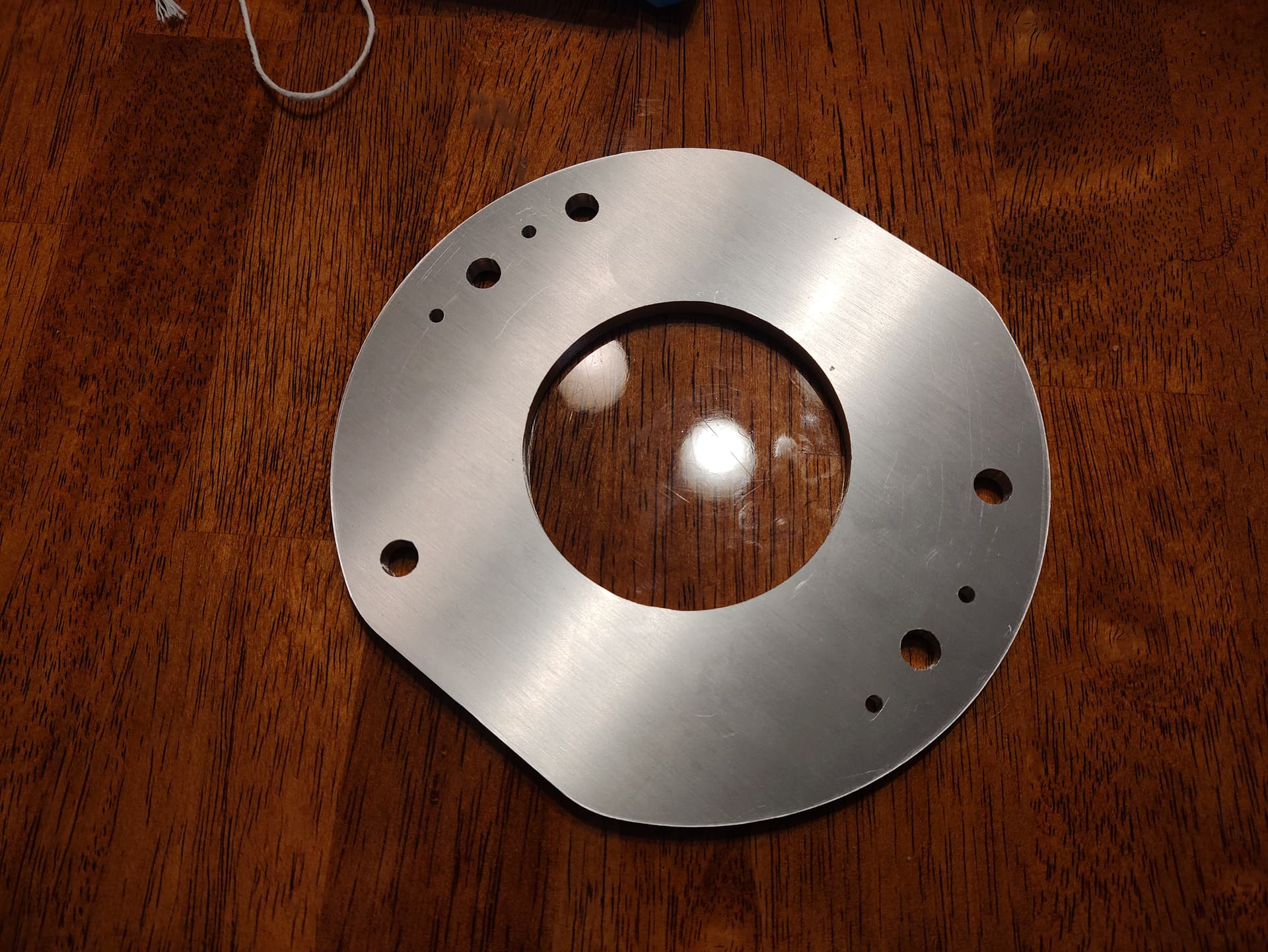
2nd, I ran an aluminum job last night and results were mostly good. Dimensionally I was pretty happy, but there was some significant taper on the walls that caused the dimensions to vary on one side of the plate.
Some of this could have been tool wear, or maybe I need more finish passes, but the cutting went well/was uneventful. Fair amount of chatter, but again, maybe dull tool. Chips looked good though.