99% of the time, I’m cutting less than 1.5" stock. Anything over 3" I would expect to need a drop table which would be on me to build as the table isn’t really part of the design. I don’t know how you cut over 3" of Z with a standard trim router and endmill… so I would imagine those use cases are custom builds no matter what. Large amounts of Z aren’t really appealing to me FWIW
1 Like
I would have to agree that a fixed gantry would be nice and limiting possible z travel would be acceptable. From what I see most people use these machines to cut plywood. If you want to make a foam cutter that can do 8" thick slabs then a different design would be the answer.
A fixed gantry can also greatly improve dust collection as the dust boot can remain on the surface and the router moves up and down through the boot.
If you stick with the rolling design the y plate ears actually have a lot of flex. Simply doubling them up and having one y plate on the inside of the 3d printed parts and another on the outside really stiffens it up. You could probably get away with two pieces of 1/4 with this approach.
There is a company selling a 48" wide cutting area CNC with ball screws and touch screen for <$3,000 USD. I have not yet taken the plunge to try it but some of us are probably getting close to that investment with our lowrider mods with material and time. I think ball screws would really set a rev 3 version apart from machines like xcarve but can appreciate the complexities it adds.
1 Like
48x96" with ball screws on all axis? Can you link it please? If that is actually the case, it makes it even more clear I should not be pursuing that. If anything, I should be trying to make this cost less than it already does. Ball screws are cool but I am not sure why everyone thinks they are going to solve anything. Linear accuracy has never been an issue for us, ever.
Just to add to this, I can not inexpensively ship anything larger than 12x12x6". Anything larger needs to be purchased separately. This is true for the US and exponentially so for international orders.
3 Likes
Like V1. The new version will most likely go back to this…depending on the X axis gantry assembly, and if it hangs off the table.
It’s not 96" long only 48" x 32" but allows you to slide a sheet of plywood through. I didn’t want to openly share a link because I didn’t find it appropriate but since you asked it’s www.onefinitycnc.com.
1 Like
Sort of, I was more talking about one plate on the inside of the z rails and another plate on the outside. The inside plate helps keep chips off the z screw as well which is nice when cutting aluminum .
1 Like
I tend to agree, why venture out of a market that you really have a corner on?
I look at my LR2, and I think of improvements, but really, I’ve left them pretty much alone. I fit the countersunk screw heads to improve cut depth performance, but with the longer bit, it’s pretty good. I may still look at doing something to reinforce the wheel tracking, but that’s unlikely to get more fancy than a couple of strips of material to go inside the wheel tracks. Basically all I’ve done is the Primo-style belt holders, and add the endstops to a stock build. Well, and used the Makita instead of the DeWalt 611.
2 Likes
Interesting, Never seen that one before. I will have to find some videos. $2820
Yeah pretty neat, they seem to be popping up on some woodworking YouTube videos here and there. If you got rid of the fancy screen, controller joystick you could probably knock $1,000 off it. I don’t know if the vertical stack of the x tubes is good because it would have more load horizontally than vertically where your design is superior. The lead screw and horizontal rail mounts looks like they could be from some custom extrusion simply cut to length and some minor machining. Custom extrusion dies are around $5,000 offshore so not too bad actually if you are moving decent product.
1 Like
Something I think is an interesting concept is how (in a generic sense) the size of a joint (including a rolling joint) affects stiffness in tipping, and could that be a degree of freedom chosen for the application.
The X tubes could be farther apart, or the side plates could be wider and/or taller (meaning they hang down lower), or there could be great big gussets at the X/Z joint. Making these larger will generally decrease the usable workspace size (or increase the consumed footprint), and there is a trade-off between eating up valuable workspace and increasing stiffness. Weight is also a consideration, both in how it affects speed and also possibly the Z axis (which could be a single-start leadscrew and then it’s again back to speed).
In some circumstances the extra size and weight might carry very little penalty, and that’s essentially the only cost. The monetary cost is effectively zero.
One problem which is a somewhat serious one is that people will assume that the stiffer one is better, no matter how much you tell them otherwise. I don’t know how to solve that.
So this is not so much what I would want to see, exactly, but an idea to throw into the mix. I have also considered things along these lines for MPCNC but that is a topic for another day.
1 Like
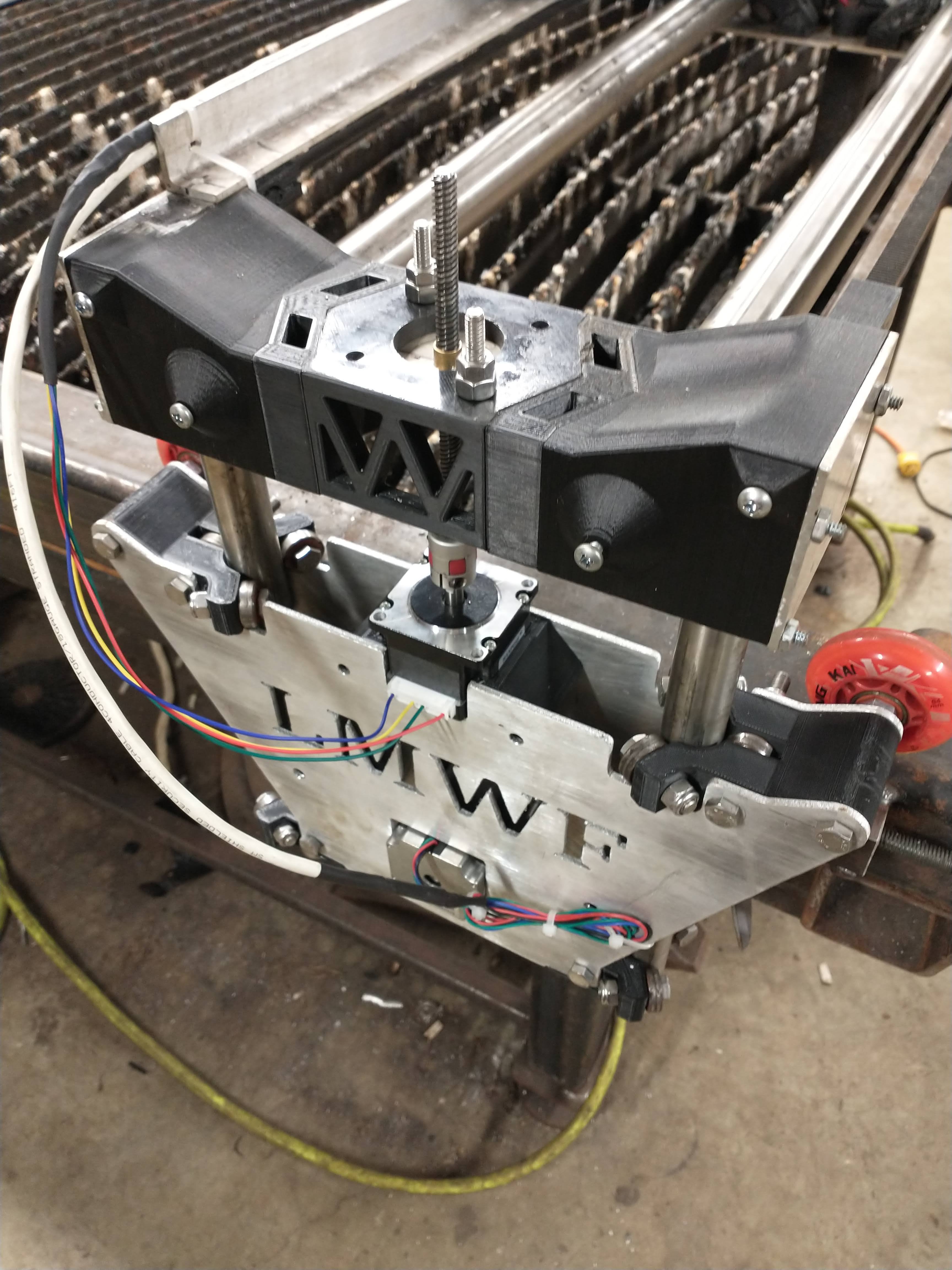
That’s what I ended up doing, I also made the y plates wider by about 1.5, added rollers to the inside plates so the gantry couldn’t track back and forth and used 1.25 tube for the x rails. This design has held up well enough that it no longer breaks parts, rapids at 3000ipm. The biggest issue I’d say it has is the gantry pivots on the z screw. For plasma, not a huge issue and I think I fixed box style gantry would limit this, even when the gantry is slammed u can stiff push down on either end of the tower and watch it rock as well as when the torch is in center of x u can easily tip it along the x axis. Ie one tube lifts and the other lowers. Keep in mind that with the 1.25 tubes and being spaced another 1.5inches
1 Like
I know, because your machine is where I got the idea from in the first place ![]()
1 Like
An idea I was having, as a beginner, was roughly the following:
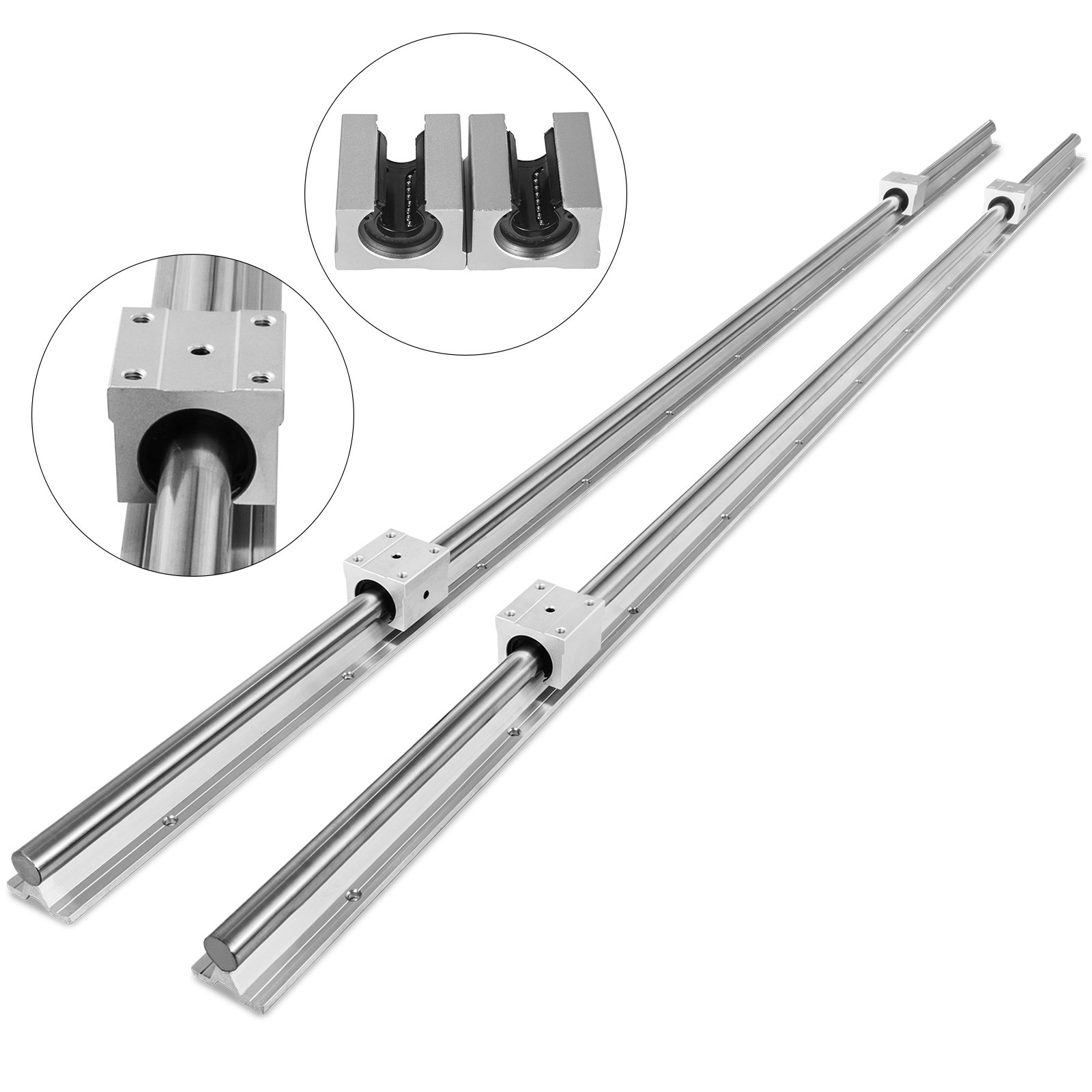
Keep similar design as the Y plate, but make it higher. Drop the skatewheels and use a linear rail instead. Screw two bearing blocks on each Y plate instead. This would mean that you would mount the linear rail to the side, and not on top of the table.
I believe this will make it rather easy to level your workarea even when the alignment isn´t 100%, and is pretty similar to what others in the forum do by mounting struts to the side.
To give an idea on pricing; link 140USD for 2x 2200mm
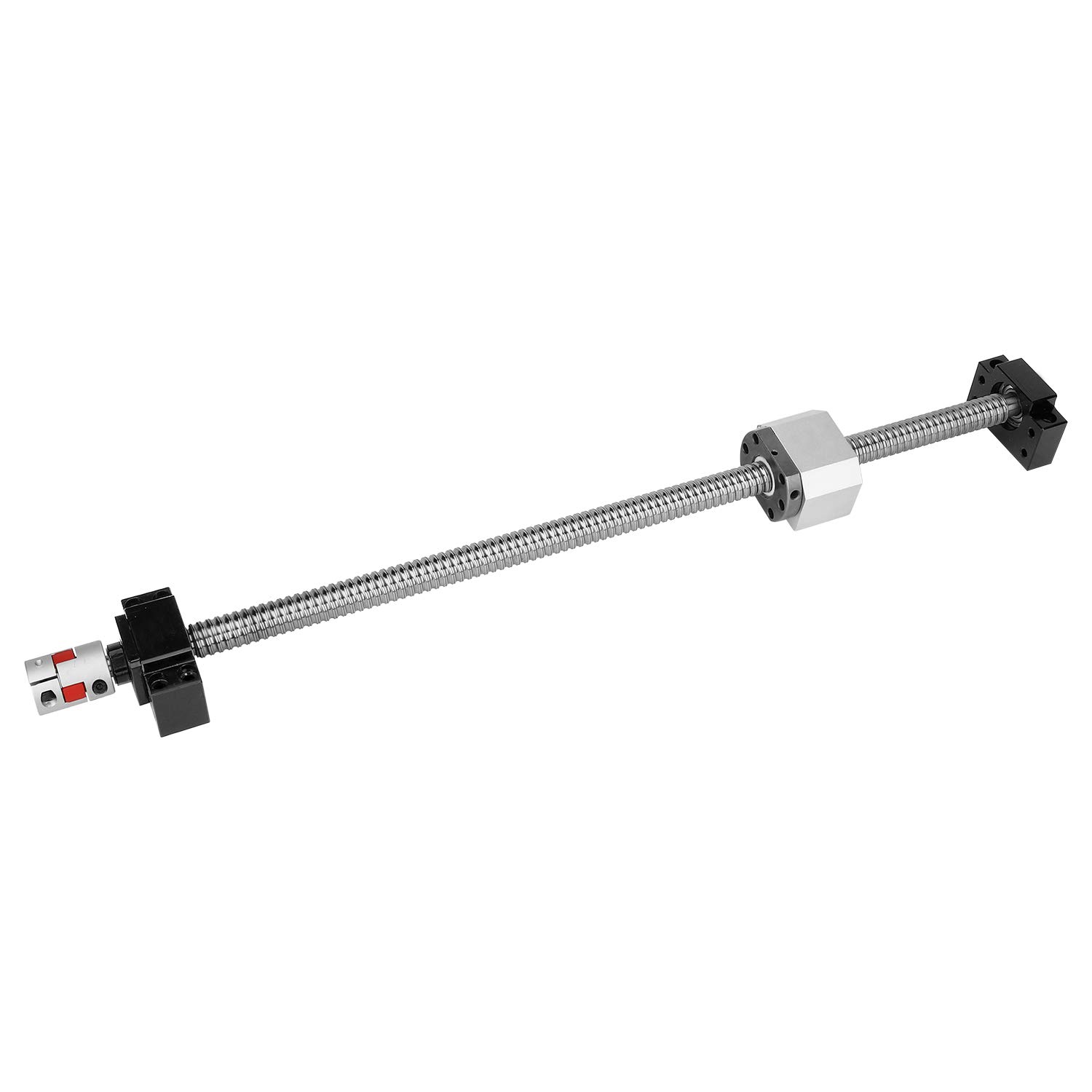
For the Y movement one could keep the design of the belt and motor in place. A potential upgrade, with little change needed, could be a long ball screw, where you could attach the carriage with a simple L bracket – on the same place as the Y motor is mounted in case you´d use a belt… In that case you´d mount the stepper to the end of the table.
To give an idea on pricing; link 220USD per ball screw
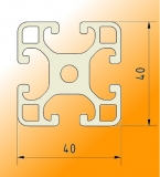
The X axis could be easily made, in a similar way as it is today, but one could use 2 slot profiles instead of 2 tubes.
To give an idea on pricing; link 30USD per profile
That way you can easily mount the profile by using an of the shelve bracket. If one would mount 2 brackets per profile, per Y plate, I imagine it would be rock solid with little play.
To give an idea on pricing; link 2EUR per piece
If the slot profile wouldn´t be an option, one could just use a simple square tube instead that mounts with a bracket too.
To move along the X axis, you could make an X plate that uses bearings, like we are using now. And again we could use a belt and stepper motor like in current design, or go with an upgrade, a ball screw.
For going up/down the z axis, one could make a custome design like the primo, or maybe just mount a ready to go assembled Z axis that screws directly on the X plate?
Like this;
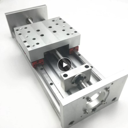
One caveat would be that there is limited height, like one mentioned before. But for this one could easily adapt the table so the workbed is lowered. So the x axis is always the same height, but the Z axis lowers down instead?
Hope this makes any sense, I know it´s rough, but I believe that it´s doable, and for a price < 1000€ depending if you´r going “stock” (belts, wooden plates) or the “upgraded” version (ball screws, alu plates).
1 Like
I know this problem from my own little company. You´d want to work together with a distributor that can ship directly to your end customer. They have special shipping contracts, so why not do it this way:-)
1 Like
I see stuff using Al extrusion all the time on cnczone, and the problem always seems to come back that ultimately, Aluminum wears over time. Faster feed rates, the tool hitting something and causing it impact, and you’re replacing parts fast.
For me, one of the things that was very attractive about the MPCNC and LR was that the mechanical ways are steel. This means that they are durable, easy to source and for most people, inexpensive. (For me doubly so, given where I work.) Aluminum extrusion is an increase in cost, and a decrease in durability, so even if it solves other problems, it’s not much of a step forward.
I don’t know if square steel tube would solve the problem, but it’s still relatively easy to source, is still steel, and still cheaper than extrusion for most people. We’ll still end up with a metric/Imperial measure difference, where I’ll grant that extrusion usually doesn’t have that.
3 Likes
Never thought about it in that perspective.
In context, has to be both the funniest and saddest thing I have ever read on this forum.
But as it has been said before, you provided the genesis for ALL of it. And without your vision and abilities, (and sweat and tears and frustrations I’m sure) none of it would have happened.
For that,we all owe you a debt of gratitude.
Still waiting for something so I can use nema 34’s on my mpcnc, but I’m not complaining…
3 Likes
Right now, at leaste here, a 3x3x.125 wall tube is cheaper in aluminum then steel. Ie a 4x8x.125 sheet of hot rolled is about 225CAD . The same in 5052 aluminum is 160.
1 Like
I second this! The original mpcnc totally set me on the path to where I am at now. I think I have built 8 v1 machines if I include my last versions which are very much, just a modded lowrider. Also getting the first as a complete kit minus the printed parts with clear instructions gave me the basic knowledge and confidence to go from there. I never even had touched cad untill a couple years ago and for that also owe thanx to Ryan and his machines / community
9 Likes
Although I am way far off the moment that this will be an issue for me, you´re right. Looking on my previous (none CNC) Alu experiences it´s great for some time and then things just break.
The annoying thing with steel is that it can be expensive, or sensitive to corrosion.
Although I believe the additional cost for replacing part with steel isnt such a big factor. The amount of hardware needed is limited.
If comparing prices, like DarXidE is doing, I can see in my area:
- alu 40x40x3mm; 23,21€ / meter
- steel (304) 40x40x3mm; 65,52€ / meter
So I can say the price will go roughly by factor 3. In the end, it depends on the user what he´s willing to use. For instance, some users seem to use perspex for the plates.
That´s indeed the biggest issue. Sorry to ask, never been to the US, but I thought that metric is the norm by now, no? Or does that still depend on regions or specific materials?
1 Like
North American material is mostly all imperial. I also highly doubt aluminum square tube with .125 wall with bearings riding neat the corners would deform like some had mentioned the pipe has… I think the cases qhere that happened ppl were using very thin wall. If the bearing causes the wall to flex then 100% it will work harden, and on round pipe, yes flat spots can definitely form. But a flat surface I am almost certain would stand up. I’m pricing out 3x3 thin wall stainless but I’m thinking 1 it will b seamed which isn’t ideal. 2 I can’t see it being easy getting .100 or less and that’s fairly heavy. I may have to put my theory to the test with all my ass time I have recovering. Hard to use a mouse and keyboard with only non dominant hand lol. I have been wanting to update my lowrider v2 router to use a pc and such anyway. I avoid using it now that I have played with Linux and even Mach 3… I like the way u just jog with arrow keys, when u let go it stops and the reliability as well. Maybe it’s just because it’s still run by a pi and ramps board however. I have never tried any of the nicer boards most of u all use
2 Likes