I am a beginner for everything with marlin and software modification.
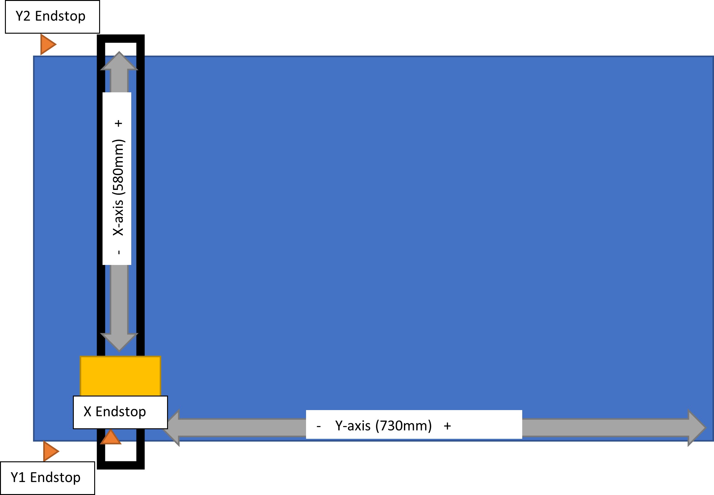
I build my Lowrider2 CNC according to the documentation that i found and using the Kit from V1. Unfortunately, i made a mistake along the way and, while the machine moves in every direction and my dual endstops also work, i did mix the direction of the x and y axis up. i made a sketch to explain my setup.
.
I did not include the z axis on this drawing as it is not the problem.
The result of this is that now, everything i do is mirrored: if i want to move the machine along the x axis, it moves on the y axis and the other way around.
I tried to change the firmware by myself but i got confused and i really don’t want to risk damaging my machine.
Do you know where i could find instructions on how to switch the x and y axis in the firmware while keeping my endstops?
Or maybe could someone with more knowledge just give me a step-by-step instruction to modify the firmware?
i already have downloaded the firmware from github and opened it in platformIO, and i know how to flash it on the machine, I just need the steps in between.
It is unclear to me what is the root of the problem. If when you ask for a move in the positive direction it moves negative instead, then you can just rotate the connectors for both steppers on each axis, and you will reverse the movements of the steppers. No firmware changes needed. If you are using a non-V1 version of the firmware, then I would use a ‘diff’ tool and compare the configuration.h and configuration_adv.h of an official V1 version of the software and your version. I use ‘Meld’ as my ‘diff’ tool these days.
Yes, everything is going to come put mirror images that way.
There are a few ways you can fix it. No matter what though, you’ll need to change that coordinate system.
Take the gantry off of the table and rotate it 180° This will put the X endtop on the other side of the table, so that your 0,0 coordinate is in the right place. (Or rotate the table 180° underneath the gantry, lol) This will reverse the coordinates so that you don’t get mirror image parts.
Move the Y endstops to the other end of the table, and reverse the Y direction by reversing the connections for the Y motors on the mainboard.
Alter the firmware so that either the X or the Y homes to the max position. I don’t recommend this, since it means that you’ll never want to start cutting from the home position, and always need to move it after homing, which is going to get annoying. You’ll probably end up just never homing the machine, in which case, there’s no point in the dual endstops. (though you could home/square Z) Let’s say, for argument that you decide to swap the X home direction. You would change the home direction in the firmware to max. You’ll have to change the motor around so that positive moves towards the endstop. Then you tell the firmware that the X endstop is at 580mm. Then when you home the machine it will be at 580,0 and when you start cutting, the X axis will move back across the table before it starts. Of course you could also do this for Y… but I really don’t recommend that.
If you really want the 0,0 to remain in the same place, you can swap the X and Y coordinates. This means that the dual drive motors become X0 and X1, and the motor on the router platform becomes Y. In order to do this, you’ll need to change the configuration_adv.h so that they Y drive is single, and the X drive is dual, and move the motors around. You can probably get some help with that, but we’ll absolutely need to know which board you’re compiling the firmware for in order to be able to manage it. You’ll also then be running a “one-of” firmware, so updating would be problematic, if you ever wanted to.
Basically, the first solution is the easiest. Unless you can’t rotate the gantry 180° because of the electronics mount and table position, but then rotating the table 180° still works. This is effetively the same as changing the Y endstops to the other end though.
If you are standing at the end of the table, X=0 should be by your left hand with the Y=0 being close to you. As X increases, it should move to your right. As Y increases, it should move away from you. This is the assumption that your CAD and CAM processes are working from. Some CAM can “mirror image” the part, so you could just work it that way, but I don’t recommend it.
#4 is what I ended up doing for my dual endstop LR2, as I am accustomed to working in “landscape orientation” and wanted to keep the stock V1 touch screen layout.
Like you said though, if you ever want to update the firmware, you need to be mindful of the changes to the configuration_adv.h