Hello everyone! I’ve been following this proyect for quite a long time (since LowRider release) and I was fascinated by the flexibility of the MPCNC to perform different tasks (as cnc, plotter, engraver…).
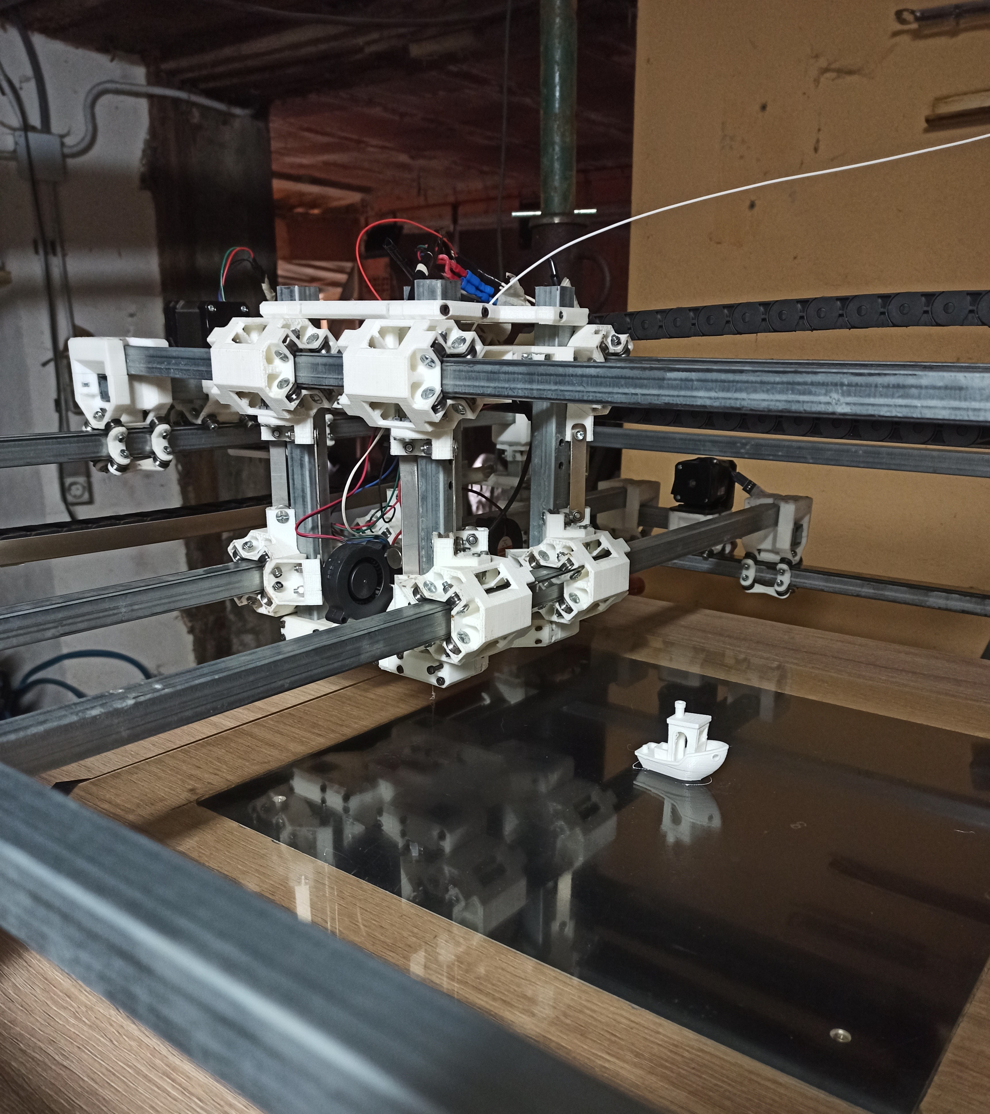
My plan was to make one but with bigger z height (3d pinter nerd, with some knowledge on milling soft materials). In the end, due to that change and being unable to find the tube profile that the MPCNC uses, I ended up 3D modeling a heavily modded MPCNC, but extremly woobly while printing.
I can print at 40mm/s with pretty nice quality (still tweaking SuperSlicer settings), but I still feel the structure is not enough rigid and the bed cant be lifted properly by the Nema17 motors with 8mm threaded rods.
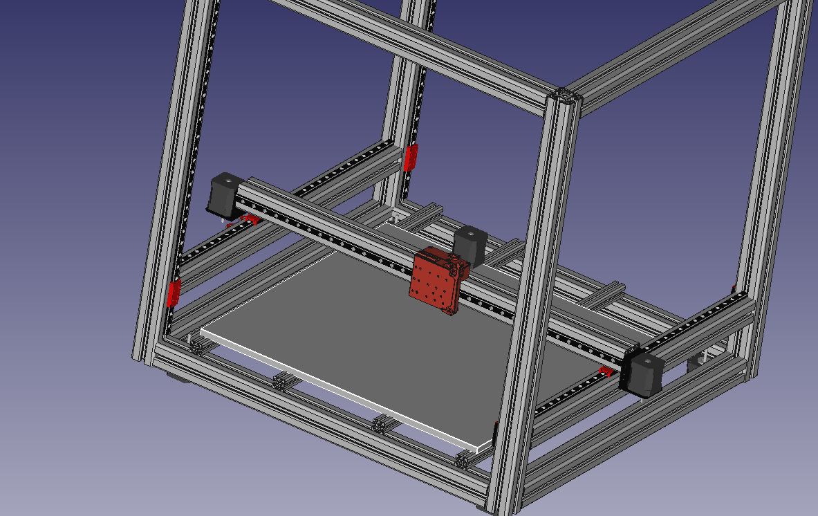
Already thinking about a new version (lets call it legit V1) using aluminum profiles (thinking about 3030, so I can change the tool head and be able to do some soft milling (I have a powerfull router catching dust). The idea is to make X/Y movement as in LowRider (but with the aluminum profiles) and make the z axis and structure similar to Voron 2.4 (but changing z movement with threaded rods).
The main point of this post is to thank Ryan and all the comunity for the tips and tricks, for this awesome idea and for giving me enough confidence to not buy an already asembled 3D machine and make my own.
Maybe in the future I end up building a LowRider, who knows.
Have you seen the BOx build by Dui? He built it very big and didn’t use cheap parts, so it will be pricey, but he did what I think you are trying to do. This is a cool looking beast.
It looks like you probably built a very capable milling machine but tried to print with it. Printers have a lot of direction changes and need the machine to be as light (less massive) as possible while being just rigid enough, while a Milling machine needs to be as rigid as possible while being just light enough. If that makes sense.
I tried to bridge the Gap with the first versions and make a balanced machine and tell people to print at slow movements speeds and a large nozzle, and have been transitioning to not telling people to print so I can add mass to increase the milling abilities.
I guess my advice is choose if you are building a printer or a milling machine and follow it’s needs.
In the early days of this build I was very impressed by his build. He was kind of the inspiration on trying to make the z axis higher (seeing his results without modding the original MPCNC very much).
I need to check his build and see how its going. I maybe get some new ideas.
My fist question would be “Where is the wobble coming from?” Triangles are one of the most effective methods for improving rigidity as both the side lengths and vertices are fixed. A couple of diagonal braces across those large sides, or panels securely attached to both vertical and horizontal members, might go a long way to firm up the structure.
I’m reminded of the early Prusa-mendel rep-raps made from threaded rod. The sides were just big triangles and were pretty rigid in that direction, but then were joined with straight lines to make a square when looked at from the front. They suffered from pretty bad side-to-side wobble under certain conditions, like heavier direct-drive print heads changing direction quickly on the X axis.
Good point on that! Currently the problem is the hole machine shakes in drastic movements so I dont know how it will perfom milling soft woods or foam.
I hope with a stiffer frame and a less overkill X/Y system I will be able to print a little bit faster (I just want the speed of a standard 3d printer, nothing super fast).
I’ll post updates when I finish the design of the new frame before buying the parts needed
I can’t point where the wobbles came from, but while printing if I touch any part of the frame, I feel the vibrations (at 40mm/s they just affect a little the print quality, but it’s not a very fast speed).
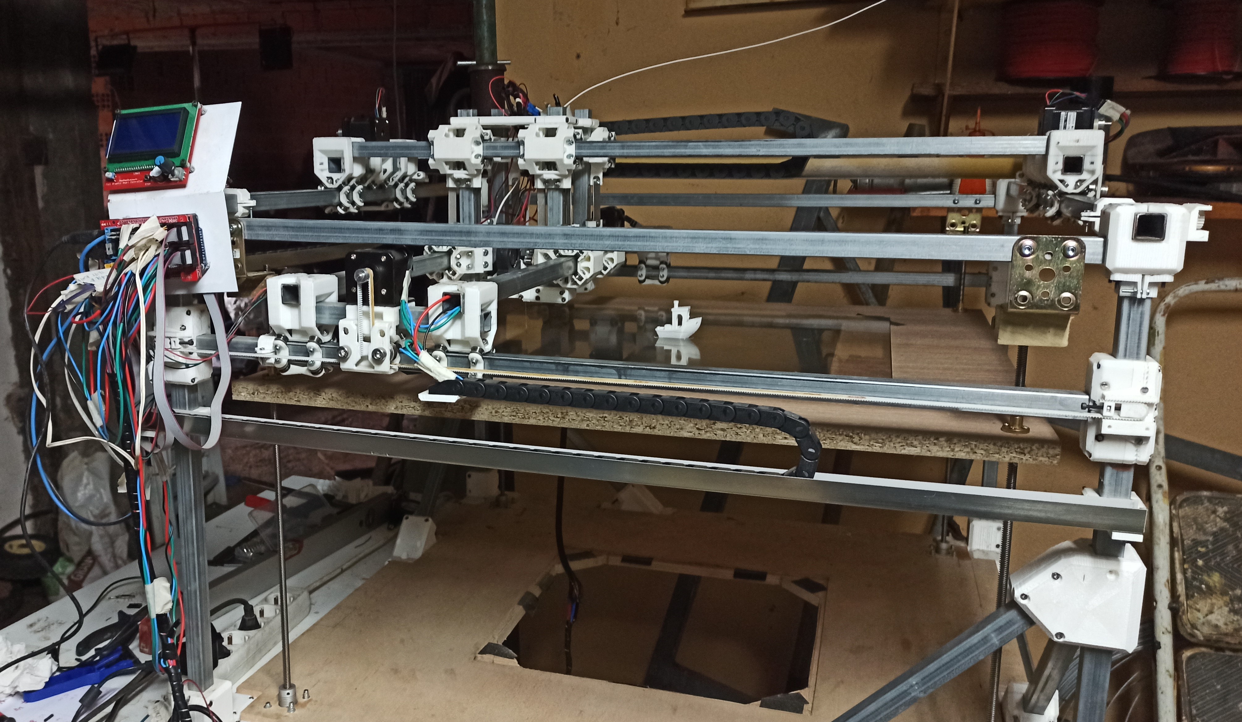
Another problem is, altough I have a BLTouch instaled, the motors lifting the bed had some problems keeping the bed leveled, so I have to level the bed before any print (the bed is lifted by 4 Nema17 84oz motors, the same as in X and Y axis). So with the new frame I want to keep the bed still (as in the original idea), but make a rectangle with X/Y axes that will be lifted by those 4 Nema 17 motors with maybe bigger threaded rods and linear rails.
The good thing about Voron firmware (Klipper build) is that each of the z motors has their own dirver, so they are autoleveled by the firmware itself and also is not the same lifting the extruder and some profiles than lifting the heatbed + the weight of the 3d printed filament.
Aditionaly, de big downside of this build is the enormus amount of 3d printed parts (making very time consuming building another machine) , while with the Aluminum profiles you already have metal joints (and problably the total cost wont vary that much).
Little update: After a couple of days printing, I found a little big issue with the printer.
The Z motors lifting the heatbead struggle a little bit keeping the bed leveled (I have to level de bed before every print, even using a BL Touch). Even if there were with current the Nema motors, today they wanted to keep the bed uneven (but always with the same inclination).
After a big headache trying to level the bed again and again, I started to think if the motors had enough torque (they can lift the bed, but maybe they dont have enough torque to keep the weight while they are not moving).
I read in reprap forum that some people have similar issues (bed going all the way down when they turn off the printer) and the suggestion is to add a Worm Gear Reducer to the motor.
Do you think that reducer will improve my situation?
Steppers lose torque at higher speeds. If you add that worm gear, they will have to move a lot faster, so they will drop in torque. You could just go slower, but I think the extra part probably isn’t worth it. You could also replace the leadscrew with a T8x2 (one start leadscrew) and get a 4x reduction. But that has the same problem.
You could set up dual endstops on Z, and make it adjust the Z each time it starts.
You could print a bracket for each side to clip on before powering off. The brackets would hold each side at the same height until you powered it on again.
There is also some configuration for measuring at each end and sloping the whole mesh.
I would expect running the G29 at the beginning of each print would be enough to fix this, but not if it got very weird.
I run G29 every time I print, but if the bed is very weird as you said, it skips the process cause the BL Touch is unable to touch the bed.
That’s what I’m using right now (I tought they were called threaded rods, sorry)
I also asked on the RepRap forum and they told me that 4 lead screws are over constraint, and suggested me to move 3 lead screws with one motor and drive those screws with a looped belt.
Today I wanted to record how it behaves and, what a surprise, I leveled it pretty easy. Only during G29 I could record in the last probes part of the issue.
After finishing the test and turning the printer of, the bed returned to his “standard” state of uneveness.
So wait, you have 4 leadscrews, all of them are one start? How heavy is the gantry? The friction in that should be able to hold a lot of weight. Even on the low rider, two one start leadscrews can hold up the whole gantry and the router. I think I am misreading something. Maybe the video will help.
Also, looking closely at the pictures, I noticed you have white belts. If those have steel cores, they will break from the repeated bending around the stepper pulleys. You don’t be able to see the breaks, but some teeth will just end up farther apart, and you’ll end up with lower tension. The fiber reinforced ones are plenty strong. But they don’t look as cool.
I didn’t know the existance of the reinforced ones when I bought the belts, i just picked the ones with best rating on amazon (and the white color was an extra). Yes, they have steel cores, but I already see on Y axes that they are bending.
I have 4 leadscrews of 8mm lead and 2mm pitch. Each one is conected to a Nema 17 84oz and 4 of them are controlled by the same driver (2 motors conected in series as if it was a dual z motor setup). However, I didn’t put any linear rail/guide, so I know that’s a problem.
This 4 motors with the leadscrews lift the heatbed only, but the heatbed is placed on a piece of wood (not a heavy one, but it’s still wood)
Oh, wow. I didn’t notice the whole build plate was motorized! I thought this had something to do with the Z.
Ok. From the video, it looks like the motors are skipping steps. Is that right? They kind of “chunk” back a little while trying to drive up?
It looks like these are 4 start leadscrews. T8x8mm, which means the distance between threads is 2mm (2mm pitch) but there are 4 separate threads. If you look at the end, you will see them all. One rotation moves 8mm. Your steps/mm would 400 with 1/16 microstepping or 800 with 1/32nd. If you replaced those with one start leadscrews, you would move at 4x slower speeds, but have 4x lifting force. T8x2mm screws have only one thread, so they move 2mm with one rotation. The steps/mm go up to 1600 or 3200. That is effectively the same as installing a 4:1 gear box on each motor.
It is true that 3 points make a plane and having 4 screws over constrains the bed. But there is some flex and they should be moving very close to lock step. Physically joining them with a belt might help, when the motors are off.
I am convinced you should order some 1 start screws, and print some kind of hard clip to hold each corner of the bed at a set height when the motors are off. That will make it consistent enough that the marlin mesh can handle the errors. The new screws should make it have enough power to lift the bed without skipping, but you will have to go pretty slow, like 4-5mm/s max.
Yeah, that’s right. I wasn’t understanding the 1 start thingy but now I remember.
After building this machine I’m pretty confident saying that with 4 points is easier to level a surface (is very hard to find a perfectly flat surface, even more this large)
With this tips I think I’m going to buy new lead screws (It’s the Z axis, so I dont mind if it goes slower) and maybe linear rails for each corner to make it sturdier (I was already thinking on buying them for the future frame). I’ll also buy that reinforced belt.
AFAIK, all belts are reinforced. They are usually reinforced with fiberglass or kevlar. The white ones are reinforced with steel (which breaks when it bends too much). So any black belt GT2 belt should be fine.
Hello everyone! The lead screws and the belt arrived today. When I have some spare time I’ll replace the parts.
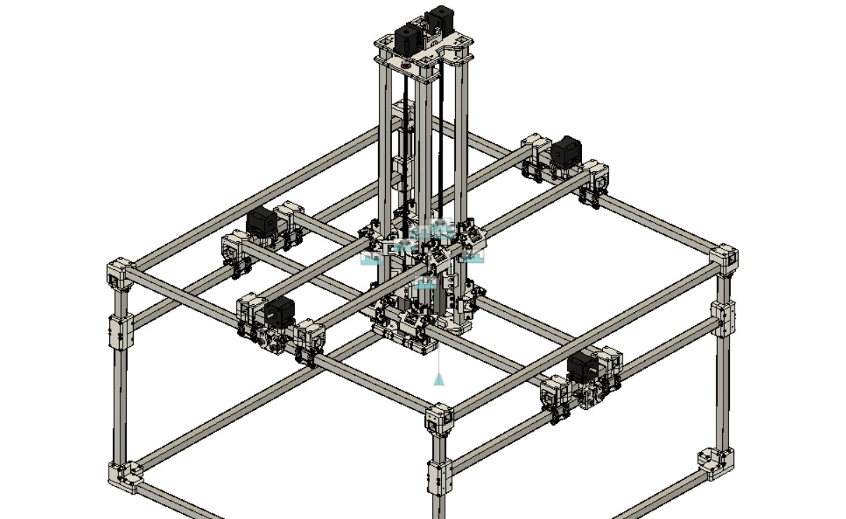
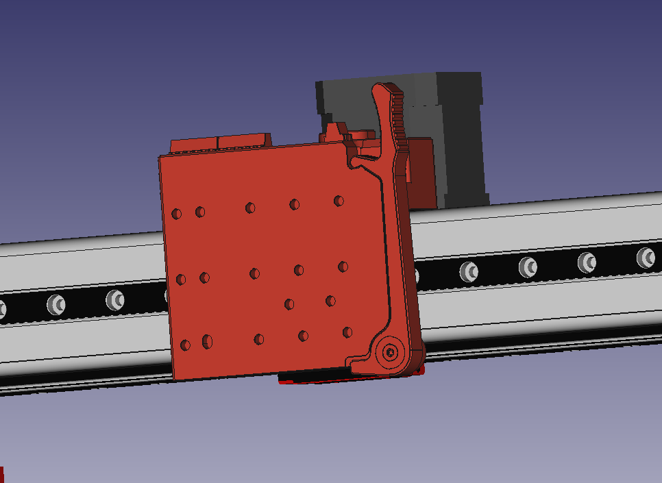
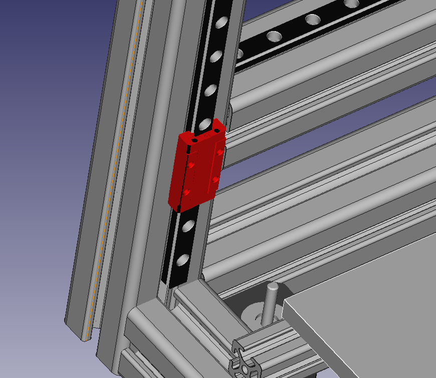
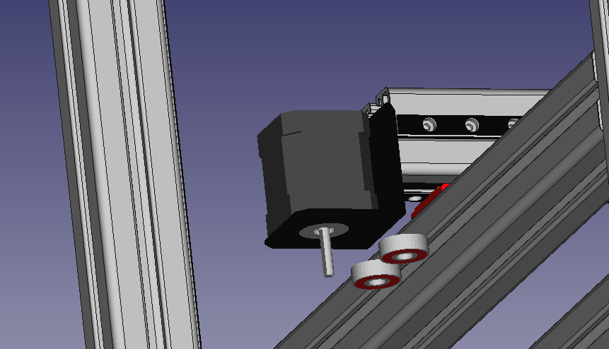
During this time I’ve been doing some research and CAD for the future frame. I’ve decided to use 4040 aluminum profiles after seeing Snapmaker 2.0 frame and also their future XL version
Changing a little bit the Voron CoreXY design and using (If I’m able) a DIY version of the WhamBam Mutant Tool Swaping System, here it is a basic 3D model
X/Y axis have the nema Motors similar to LowRider design and the Z are 4 nema motors with lead screws lifting the XY profiles keeping the heatbed inmobile.
The idea is to hide the belt inside the 4040 incisions (they are 8mm wide).
Do you think is an improvement of the messy current build? My alternative is to build a standard CoreXY printer and use a Dremel with the flexible extension in the few cases I will want to cnc.
I owned a Snapmaker 2.0 one of the biggest issues where the linear rails. The berings in the rails where too small and where exposed to too much force when milling. Caused all kinds of rail failures.
I personally wouldn’t go for a 3 in one again, to many compromises going that generic. I would recomend building the mill and 3dp as separate machines.
I know separate machines is the best solution. But I dont have enough space.
My priority is to have a reliable 3D printer (something that I don’t have right now). I’m very interested into building a Voron 2.4, but the max recomended volume is 350 and I have a 410x410 heatbed and a 500x500 tempered glass.
I doubt the 2020 frame will work fine with this dimenson and, of course, the CoreXY would be unviable due to the belt length.
