Seem to be having an issue with my z axis on the lowrider 2, wired in series. When I raise them, they go up at slightly different rates, sitting a few mm out, sometimes upto 10mm. When I was testing a cut, my steppers / leadscrews were also making this sound on retraction, any ideas what might be the issue?
Video link of skipping:
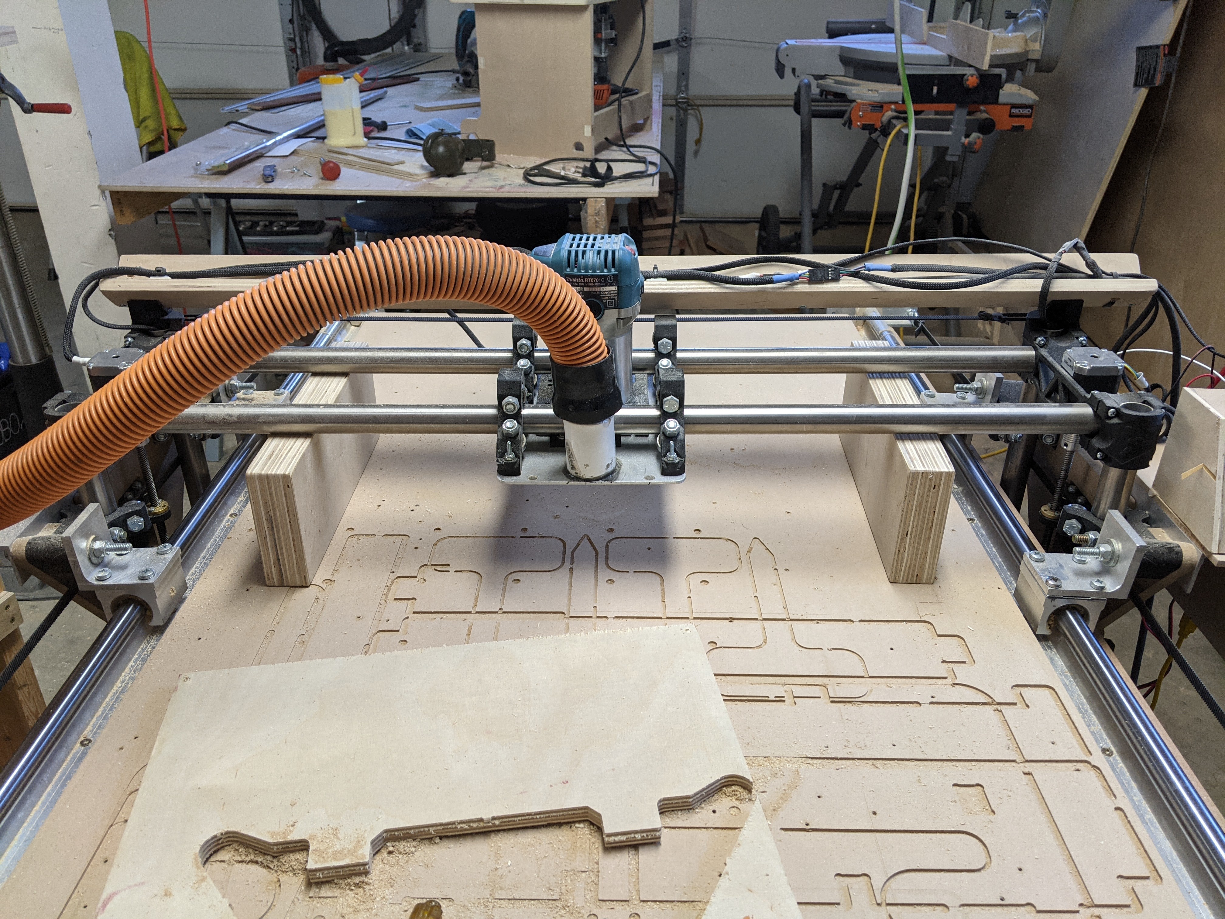
What the heck is that giant piece of plastic? Looks like it bottoms out on the plastic but still tries to go down and stretches the coupler. This would put it out of sync when trying to go back up. Power down the machine and let it rest on the blocks without stretching then travel up and see if you have the same issue
What controller do you have and how are your steps wired?
The crunchy noise sounds like you are skipping steps.
The Z moves look a bit fast. What speed are you trying to lift the Z? Try limiting it to 4mm/s and see if it goes away. Then we can worry about how to speed it up.
That spindle looks pretty big, and the gantry looks pretty large. It is hard to tell from the video.
And yeah, in the first vid, your couplers are stretched. You want the motor shaft touching the leadscrew all the time. They can stretch and not return if you’re not careful.
Its running a ramps 1.4 controller, pretty sure I have the stepper controllers sitting just under their max capacity (with the added fan cooling).
I will try resetting the leadscrew couplers again, had tried this a couple of weeks back but seems to be getting out of alignment again, maybe when I accidently push the z below 0.
The gantry is not too different from the original one, its just slightly wider to accommodate the spindle mount.
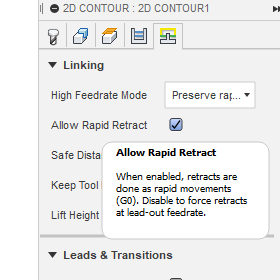
Maybe the lowrider can’t handle the ‘rapid retract’ that fusion is putting in? I’m unsure what speed that is. I can share the gcode if it helps
I can see in the G Code these lines, it looks like it is trying to move 10mm at F2400 ?
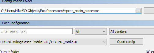
Looks like you’re not using the correct fusion post processor. There should be feed settings for every move. Marlin will continue using the last feed speed until a new speed is given. That code snippet has the Z moving from 24.5 to 14.5 at 2400mm/m.
I think what Barry says there might be the ticket. Your z moved down way faster than it moved up so something is funky with the code or your gantry is super heavy.
I would also recommend ordering new couplers. Looks like your one side at least is not returning to fully compressed. I had tried running mine with slight stretch at one point and it was just causing issues so I had to replace them.
F2400 is 40mm/s. The firmware has another setting for Z max speed that is probably taking over. By default it is either 10mm/s or 15mm/s, but those both may be too high for your beast. You cam change it with M203 Z5. Then choose M500 to save it. Or you can change it from the settings in the lcd.
I’m using this post processor, which I found was recommended, is there a different one?
I think fusion might be overriding it with the rapid retract, will try without it today.
With the couplers, yes i have noticed that one tends to stretch out more than the other, the gantry is a little heavier than your standard with my 1.5kw spindle on it. However I’m using a plastic mount for it, not a metal one I’ve seen people use with the dewalt, I’d be curious to see how much weight difference it really is. I also have a slightly thicker mdf board (16mm), considering going a 8mm alu, again will have to weight up the differences in weight.
So I fixed up the couplers, took them off and compressed in a vice for a few minutes. Then refitted in the stepper and lead screw as per instructions on the site. Nicely snug up together.
Also disabled rapid retraction in fusion and lowered the cut feedrate to 1000mm/min and ramp/retract feed rate to 220mm/min.
Seems alot happier now.
This look / sound normal?
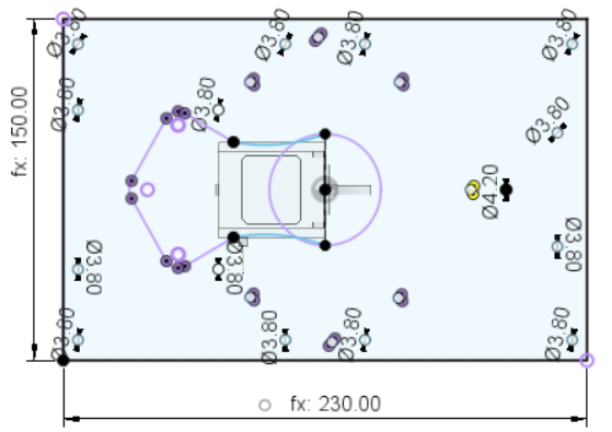
Another thing I noticed is there is little difference between left and right sides of the y/z assembly as seen here in the pictures. Unsure if it’s worth worrying about.
They should touch. You can loosen the bolts that hold the horizontal tubes to flatten it out. May have had a slight twist in it when you put it together.
Another option is to just square it with two parallel blocks between your workpiece and the rails. That way you are always parallel to your workpiece and not dependant on the tolerances between your printed parts and the straightness of your rails
I found that the gap is only on the outside, not the inside, so there seems to be some sag either from the plywood or Y Roller plastic. When I lift the Y plate up a tiny bit, its level.
I did play with it a little and improve it a tiny bit, but I think maybe a stronger Y plate and / or stronger y roller print will fix it, not too concerned about it for now. I’ve got some 8mm alu plate I plan to use for the Y plates (was thinking of milling it, but leaning towards it might just be easier / quicker to plasma cut it now).
Those two blocks are exactly the same height. Currently just holding the gantry so my bit does not rest on the spoil board. It takes out any discrepancies with prints, rail alignment ect. At the end of the day the only thing that matter is that your rails are parallel to your workpiece