Inexpensive LinuxCNC interface for MPCNC

I got some boards from jlcpcb. They are stupid inexpensive for certain sizes/layers, it’s really amazing.

As for pi linux cnc, I would love for someone to put together a whole package, Octoprint for ui, linuxcnc for gcode interpreter modified to use pigpio for high speed step/dir, and a hat for level shifters and stepper drivers.

I realize “real time” gets lots of attention but I think it’s a bit overblown. Bit banging a serial line is one thing, where being late produces wrong data, but if things lag a bit to the stepper driver it shouldn’t be the end of the world as long as the count is right.

IDL, Linux is much different than a microcontroller. The delays can be substantial. Real time is a sliding scale, but you wouldn’t want your gantry to experience huge jerks because octoprint was writing to the syslog.

Which is why things like klipper are so clever, the high level stuff can be written in python and the speed sensitive stuff can be done on a microcontroller.

2 Likes

True enough, and it wouldn’t work carelessly, but we’re talking maybe a hundred microseconds worst case jitter if its switching tasks. Processor affinity and hogging one core with spin loops should improve that.

Then in addition, pigpio uses a DMA controller for timing playback of waveforms, so it might work even without hogging one core with busy waiting. If I am understanding the api correctly it’s possible to queue new waveforms while prior ones are playing, so as long as you can stay a few ms ahead of the step/dir signals you should be fine, again based on the statement that its a DMA controller that spits out the signals. The CPU can stay out of the pin wiggling directly.

But alas, even though this would be fun, it’s not near the top of my list.

Agreed. DMA would definitely make it real time enough.

Also agreed. I have a project list too long to mess with it. I’m sure there are more qualified people working on it too.

At work, so this is all head-mulling and light side-surfing…

It looks like I could easily get a reasonable parallel breakout board that isolates the PC and does some basic setup for pull-ups, etc. for the various pins for multiple axis and I/O. I was then thinking how to repurpose my A4988’s that I got with my knock-off RAMPs/Mega combo. Then I realized that I should be able to wire up the breakout board to the RAMPs board, right? The RAMPs just takes the “usual” stepper inputs, and feeds it to the drivers. Ugly, but it should be functional, right? If I wanted to leverage LinuxCNC for my MPCNC.

Probably should finish building the rig first, with the RAMPs/Mega combo first, then work on building a LinuxCNC controller… :penguin:

1 Like

Pretty much the original topic of this thread, take a look at my first couple of posts, starting with the first one. A cheapie Mach3 breakout board and a board to mount the drivers. Looked at RAMPS first… but the little CNCshield V3 (without the Uno) worked out perfectly. Six jumpers for the step and dir signals for X, Y, and Z and a couple for +5v power (for the A4988’s) and ground. Voila! an Inexpensive LinuxCNC interface for MPCNC… :thinking:

Spent some time on Amazon looking at these. Quite some funny Engrish in the descriptions there. Can’t let this go. Read through the main documentation of LinuxCNC today. It would be good to get into that lower level of electronic control and understand it better.

So many options for boards and daughter boards and breakouts and then the ethernet path now. Then the magic FPGA boards. So much to learn.

Interestingly, the Mach3 breakout board I used can be had for < $5 on Ebay if you’re willing to wait on the slow boat… a bit more on Ebay or Amazon from US sellers. Here’s an example listing for the exact board I used (I don’t remember when/where I ordered it from or how much I paid)… breakout board.

The little CNCshieldV3 is also readily available for under $5 from Ebay or Banggood… with drivers it runs about $10… CNCshield V3. The Arduino Uno normally used with it is not required at all.

Here’s my inexpensive LinuxCNC interface board set…

with the inter-board connections for X/Y/Z step and direction signals and +5v and GND . The parallel cable and USB (just for the +5v power) connect top-left and +12v motor power to screw terninals on lower-right. Looks like I robbed a couple of drivers off of the shield after I decommissioned it…

Please note this is just “dumb” circuitry and super simple to connect up and get running… standard cable connections from PC to breakout board… and just motor connections to the driver pins on the CNC shield. And the little shield is the perfect “prototyping” board … pins and sockets, with no active circuitry other than the drivers… and all arranged very neatly and logically. And the 4th driver can be jumpered to clone any axis or act independently… I cloned it to X since my FoamRipper uses 2 drive motors on that axis.

I think you should give it a rip. Most of the extra hardware can be had free or almost ridiculously cheap… and the LinuxCNC software is “meaty” enough to really get your teeth into it and interesting/versatile enough to keep you busy for quite a while, if you really want to dig… :grin:

1 Like

I have an old Dell Optiplex that works great and has the parallel port on it. RIght now I have it as my Linux machine with Ubuntu. I use at as a test bed for different FOSS applications like WordPress and Mediawiki. Mostly it is how I keep testing my Koha library server and stay up on it. I can have a couple others I can use for this that are newer so I can dedicate the Dell to LinuxCNC

Here is how I understand what is necessary. It has been hard to sift through all the different options to understand exactly what is being referred to, especially because there is not a consistent appellation for the driver boards as I can understand it.

I kept assuming that the breakout boards actually had the drivers too. I didn’t make sense to me that you would need another board. I keep thinking of how I use an Arduino and a small driver board like the A4988 that I use to drive a NEMA 14 I got from an old scanner to drive an automatic coin sorter.

I figured that LinuxCNC did all the software and that the paralelle port got the right connections to the drivers on one board.

So you do need a breakout/mediator board from the parallel port to any drivers you use? I assume that is what these FPGA cards are for. So the breakout board is a something that takes the software logic commands and sends it to the right switches for the hardware.

Hence there is the relay on the breakout board that would go directly to switching a spindle on or off or the vacuum. Then the breakout board would also need a driver for each stepper motor. Right?

I am a philosophy and theology major. Electronics is my hobby but there is a reason why it’s called “magic smoke”.

It’s complex, but rational. I just need to follow all the lines of connection here.

Almost. The breakout board doesn’t have the stepper drivers. It just has the pinouts for step, dir, enable that you would feed to the drivers. But yes, the relay(s) would be for controlling main power to the spindle, fans, vac, whatever directly from the board without needing another power control board. There are also inputs on the breakout for encoders (not needed for open loop steppers) or endstops, or whatever else floats your boat.

Big edit (now on computer)…

The breakout board in the OP does have a relay for spindle/vac/whatever control, as well as inputs for endstops, encoders, or whatever else you fancy. LinuxCNC is quite powerful in what you can program it to do…

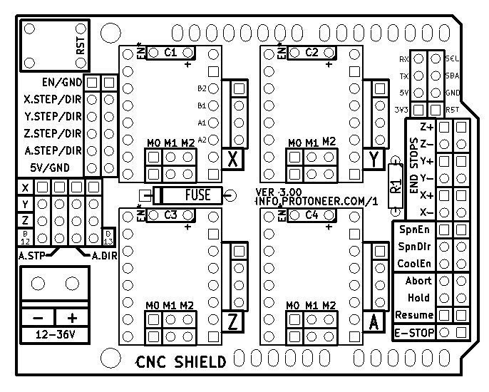
There is also a high(er) voltage input (12/24V?) as well as the 5V USB logic power input. The board is already “configured” for a basic 5-6 axis setup, with step and dir pins for each axis, and usually a common enable. There are also a few standard output pins for low-voltage controls as well as at least one PWM pin. You still need a stepper driver to take those step, dir and enable pins (plus a power source) , and make a motor move, which is the job of the CNC shield. It’s a dead-simple four-driver breakout board, really.

And that’s all you need.

Now, you get into the 7i79 (FPGA) boards (at >$100 a pop), and first, you’re usually talking about an ethernet connection, then you’re talking about a lot more gpio pins to work with (usually close to 80, I think). Those are how the “big boys” play with their big toys. That’s when you’re talking about CNC milling machines, not DIY CNC routers. They have multiple axis machines, with multiple coolant flows, tool changers, encoded servos, etc, etc., etc.

1 Like

Whilst I’m pontificating on subjects I’m only mildly proficient in (and avoiding errands that need to be run), I think that the parallel breakout could, in fact, be literally the individual pins from the parallel port. The board just has some silicate sugar around them to make them more stable and easier to work with (i.e., less likely to let out any magic smoke, or cause anything to bite you), as well as have some handy connectors to work with.

1 Like

Most breakout boards I’ve ever used just provided convenient access to the individual signals/wires “bunched together” in a connector or cable… breaking them out so you can do something with them. In addition, the signals are usually isolated or conditioned in some way to minimize the possibility of damaging the PC’s inputs/outputs… and may also include one or more general-purpose relays or power stages to drive high-powered loads. In my experience, they don’t provide added functionality beyond just breaking out and conditioning the signals for convenient use.

Here, we have all that but designed specifically to support Mach3/LinuxCNC parallel-port I/O… bringing the step and direction signal for all axes, along with some other useful signals, out to screw-terminal blocks on the edge of the board. At this point, almost any vendor’s drivers that use step/direction control (Gecko, stepstick, etc) can be connected… for CNC machines, big or small.

Note the little CNC shield has all these signal neatly and conveniently bunched together in the upper-left portion of the board… it couldn’t be simpler

And IMHO you’ll never go wrong with an old Dell PC… I was using an old Dell Dimension with mine.

2 Likes

Yes I wasn’t clear in this sentence:

I meant to say that the breakout board still would need to connect to the steppers through a driver board or driver cards/boxes.

I think I have it now. I do have four NEMA 24 steppers free and four A4988 drivers. Or I just need that Mach3 board you are speaking of.

Or do you need something else to corral these drivers. I note that there are a lot of five stepper driver boards around. Assuming that I would one day mess around with the MPCNC,

Thanks so much for your patience and help here. I really appreciate it.

You could do it with just the four drivers, but you don’t want to. Get a 4 driver CNC shield and use it as a breakout board for the drivers.

PC-parallel breakout-driver breakout-driver-driver breakout-motor

This Old Tony has a good video on it. Just replace his $300 worth of stuff with $10 worth of stuff.

If you want 5x drivers, you can just use 2x cnc shields. Just wire step, en, dir, to both boards.

You can always wire your motors in serial. It really does work fine.

I have no idea what the fpgas are used for. In my mind, fpgas are for multiple GigaBitsPerSecond stuff, or massively parallel tasks. Things like neural networks or graphics or video transcoding. Flipping a stepper driver input would be the most boring job ever for an fpga.

3 Likes

What really has me going is Marco Reps doing his new CNC mill. He is doing the LinuxCNC route.

Both he and Andreas Spiess talk about the FPGA boards like they are magic.

I know beyond the the needs of the MPCNC, but I would like to put a horizontal rotary axis on this to engrave rolling pins. I have to have dreams to keep me going and things like this are so cool.

These guys that are making the epoxy granite mills are so entertaining.

Not surprisingly, I’m old and tired and pretty quickly and easily confused by what you guys are really trying to do… but it sure seems like you may be over-complicating this… at least, for the basics. And the breakout board I used seems to be the cause of some concern and confusion. While it may seem logically unnecessary, it does provide a measure of isolation/protection for both the driving and driven systems… and mounts a few components and breaks out a few more signals that you might find handy on down the road, when you go beyond the basics of just moving the axes.

You could probably jam a few jumper wires into the end of the parallel cable and onto the pins of a bare CNC shield and get the CNC to move. You might even jam in a few more and get limit switches, etc. But at some point this is all gonna get a lot more messy than simply adding the little breakout board. And, like a fuse… being dirt cheap, readily available, and offering protection for the more expensive parts of the system, it makes little sense to me to try to avoid using it. No soldering, little/no drilling to mount relays, transistors, or extra components it already provides, etc… less kludge.

It’s not a requirement, of course, that I be able to follow along and understand everything you, and those other guys, are trying to do. But I did what I set out to do and “married” (or, at least, had relations with…) LinuxCNC and all my stepstick-driven machines, with a relatively simple and inexpensive LinuxCNC interface for MPCNC :wink:

3 Likes

This is pretty much what I was saying.

Very important reason to have a driver board!

“Just because you can do a thing does not mean you should do a thing.”

I’m really not sure what you are trying to tell me… I think we’re looking at the same coin, different sides.

I said what I think I needed to say, so will leave it to you guys to sort out what you want to do.

I was agreeing with you 100%! I know I was over complicating things, part of my ASD behavior, needing to be painfully precise…

1 Like