Issues getting laser configured properly

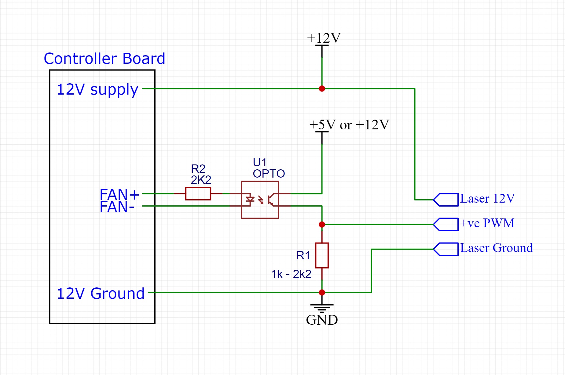
I have a 8 watt output laser that I can successfully turn on and off with the TFT35 Spindle interface, but it does nothing in the laser interface (replaced fan interface). Below are the changes I made in Marlin compiling for a BTT SKR 1.4 Turbo. M106 Sxxx (ive tried different number 0-255) does nothing. What am I missing? +12v and GND are connected to Fan 0 and the PWM pin is connected to P1.24 of the neopixel connector.

in Configuration_adv.h
#define LASER_FEATURE
#if EITHER(SPINDLE_FEATURE, LASER_FEATURE)
#define SPINDLE_LASER_ACTIVE_HIGH true // Set to “true” if the on/off function is active HIGH
#define SPINDLE_LASER_ENA_PIN P2_03 // Fan 0 pin for +12v amd GND for power and enable/disable
#define SPINDLE_LASER_PWM true // Set to “true” if your controller supports setting the speed/power
#define SPINDLE_LASER_PWM_PIN P1_24 // Neopixel data pin for +5v PWM
#define SPINDLE_LASER_PWM_INVERT false // Set to “true” if the speed/power goes up when you want it to go slower
#define SPINDLE_LASER_POWERUP_DELAY 1000 // (ms) Delay to allow the spindle/laser to come up to speed/power
#define SPINDLE_LASER_POWERDOWN_DELAY 1000 // (ms) Delay to allow the spindle to stop

in pins_BTT_SKR_common.h
#ifndef FAN_PIN
#define FAN_PIN P2_05 // move fan 0 pin P2_03 to bed bin

in pins_BTT_SKR_V1_4.h
#ifndef NEOPIXEL_PIN
#define NEOPIXEL_PIN P2_05 // move neopixel pin P1_24 to bed pin
#endif

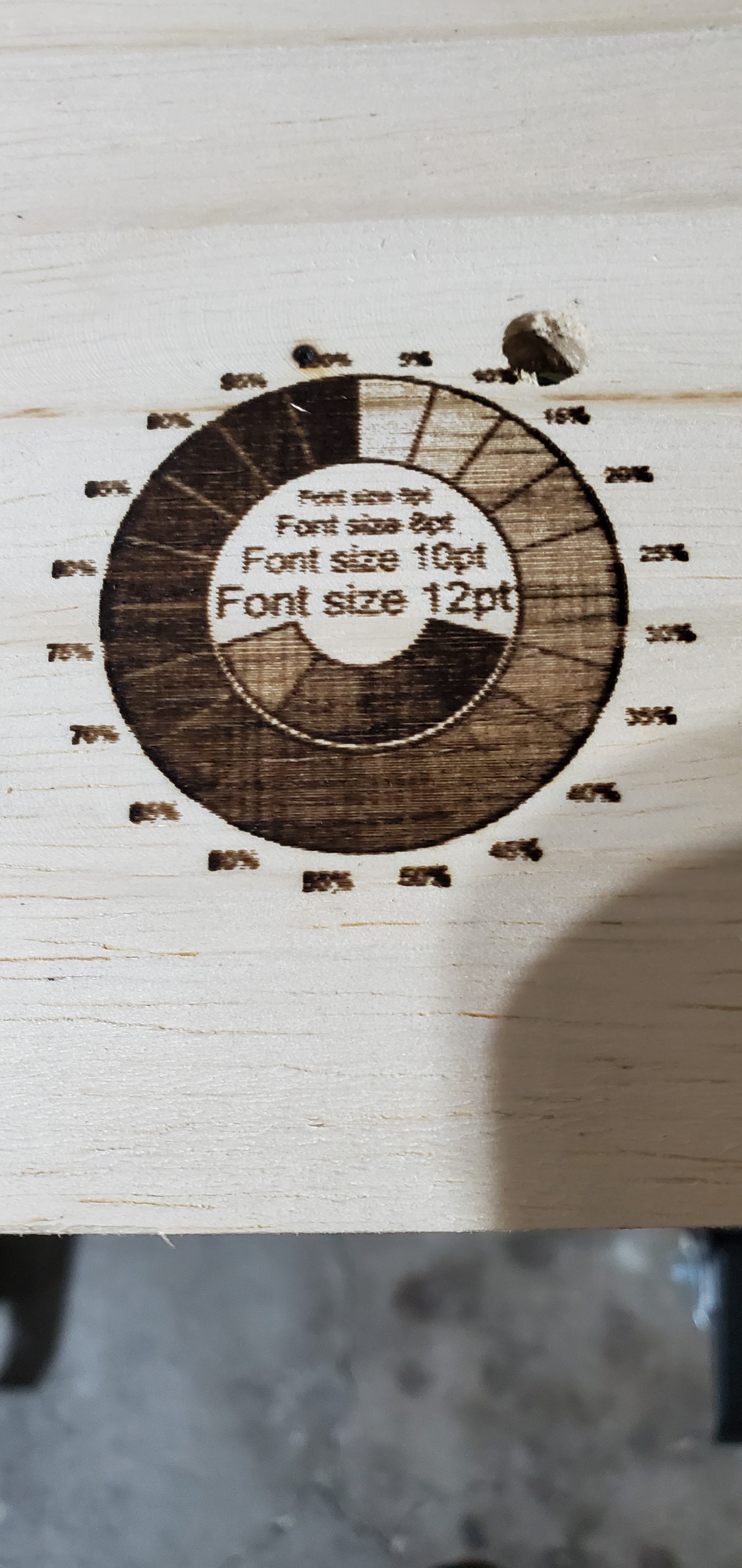
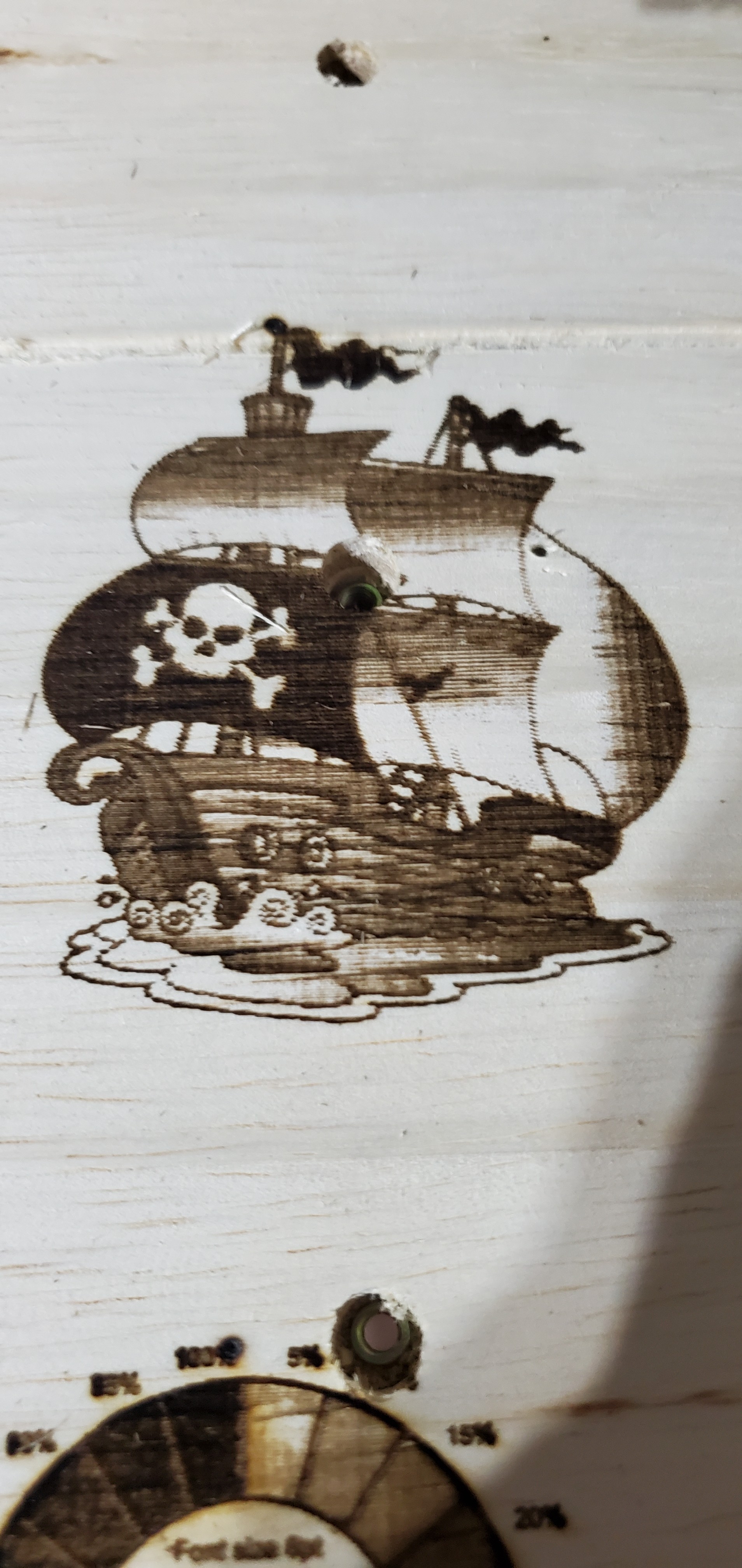
Update: M3 and M5 work, but the Sxxx feature doesn’t change the intensity.

Alright. I think I finally got it for my case, But I dont like it.
M106 P1 // turns on laser module in GCODE
M106 S25 // Sets laser to 10%

Completely disable the laser feature in Marlin (in Configuration_adv.h) and make some modifications to pins_BTT_SKR_common.h
#define FAN_PIN P1_24 // Fan 0 for Laser PWM M106 Sxxx (0-255)
#define FAN1_PIN P2_03 // Fan 1 for Laser Enable

Modifications from above in pins_BTT_SKR_V1_4.h stay:
#ifndef NEOPIXEL_PIN
#define NEOPIXEL_PIN P2_05 // move neopixel pin P1_24 to bed pin
#endif

Ultimately, I may just move the laser power to board power so the laser module is on when the unit is on or just modify my GCODE to start with M106 P1 to turn on the laser module and M107 P1 to turn it off at the end of the GCODE.

I don’t have a laser, but I keep up on the laser topics on the forum, and I’ve been able to help several people get their laser working. I’ve seen several times where fan commands were initially used to get thing up and running, but long term, there was quality issues with the running the laser using a fan pin. They eventually made firmware changes so that inline laser commands can be used, and werer happy. That is an ‘S’ parameter of the G0/G1/G2/G3 commands is used to specify laser output.

The last time I checked, of the firmware that V1 maintains, only the Rambo boards and the SKR Pro boards had firmware with the inline laser enabled. If you elect to try and get inline laser commands running for your SKR 1.4 Turbo, I suggest you download the source for either the Rambo firmware or the SKR Pro firmware and run a ‘diff’ program using configuration.h and configuration_Adv.h between your source and source with lasers enabled. I don’t know how many are really necessary, but there were a fair number of changes (some of them not obvious), between V1 maintain firmware with and without laser support enabled when I ran this diff.

Lately I’ve been using Meld as my diff tool. The first post in this topic contains a test file with inline commands.

2 Likes

I will definitely look into inline S commands within the move commands with the laser. Ultimately grayscale raster images are what I’m after.

1 Like

You can process greyscale images two ways, you can either use a constant laser power and ‘dither’ your image to produce a picture of dots that the laser can use or you can scan the laser across your output material and vary the laser power to produce various levels of ‘burn’.

Marilyn dithered using M3


some sample gcode for dithering -

G0 X0 Y0 F1000
M3 S0
G0 X8.667 Y0 S0
G1 X9 S1000
G0 X21.333 Y0 S0
G1 X21.667 S1000
G0 X22.333 Y0 S0
G1 X23 S1000
G0 X23.667 Y0 S0
G1 X24 S1000
G0 X24.333 Y0 S0
G1 X24.667 S1000
G0 X25.333 Y0 S0
G1 X25.667 S1000
G0 X26.333 Y0 S0
G1 X26.667 S1000
G0 X27.333 Y0 S0
G1 X27.667 S1000
G0 X28.333 Y0 S0
G1 X29 S1000

You notice how the power is either S0 or S1000, (full power on my machine).

Alternatively, Marilyn ‘scanned’ with M4 to vary the output power

Sample gcode for scanning with M4

G0 X0 Y0 F1000
M4 S0
G1 X0.333 S113
X0.667 S109
X2.333 S105
X3 S101
X3.333 S70
X3.667 S98
X4 S105
X4.333 S101
X4.667 S90
X5.333 S86
X6.333 S94
X6.667 S98
X7 S90
X7.333 S86
X8 S98
X8.333 S94
X9.333 S86

This time the laser intensity is modulated using PWM.

Both processes have their settings to obtain the best results according to your materials and desired effects.

I don’t use Marlin for laser work, I find it is not the best choice for the reasons you are experiencing so cannot help with your configuration I’m afraid but I can advise you not to pulse the 12V on and off to control your laser if it has the PWM feature as you are pulsing not only the laser diode but the PWM control circuitry and any fitted cooling fan as well and they wont thank you for that, you should use the PWM function.
I would however suggest you comment out the delays you have enabled, they are not needed. Can you post the gcode you used when you say M3 and M5 work but Sxxx doesn’t.

3 Likes

M106 Sxxx is working since my last update.
I have in my begin HEADER “M106 P1” (FAN1_PIN) (Physical Fan 0 connector, supplies 12v) to turn on the laser module at full power.
then
I use M106 Sxxx (FAN_PIN) (physical Neopixel pin) as this is how I had originally plugged everything up.
Custom settings in my PP:
M106 S0 for “retract”
and
in my begin Footer
M107 P1 to turn off the module at the end of a file
and G00 to go home in case I need to run it again (for cuts that may not have gone deep enough)
G00

Of course all this will likely change with the firmware I compiled lastnight. My older firmware didn’t have LASER_MOVE_POWER feature yet which may have been some of my original problem?

TLDR; I’ve gotten a better understanding hopefully.

1 Like

I’ve built off lastnight’ss 2.0.8 bugfix branch and have a working LR2 (x/y/z and endstops all go in their proper direction) laser changes PWM on G1 moves. Sometimes G0 doesn’t work to turn off the laser PWM even though it is enabled in the config (does G0 expect an x/y/z move as well not just G0 S0?). M5 also sometimes doesn’t work to turn off the laser module. This is just through manual GCODE input to get an idea of how to configure my post processor now. I haven’t tried M4 S0 as you stated above (I would use this for retracts maybe?).

On a side note, I now have noise in my stepper motors which seems to be a common issue that has cropped up with the NEMA17 steppers driven by TMC2209 drivers since I compiled on 2.0.5.7 IIRC?
Edit: found my answer

Anywho, this is the build I have M106 controlling the laser.
This is what I am currently working with that just seems to have the issues with stepper noise.

Update: tested with Ryan’s Test gcode. Turned up this.

Update 2: more more things tweaked.

Update 3: Almost there!

3 Likes

Hello ExpertNoob,
I am using a skr 1.4 turbo with custom firmware for sensorless squaring on a lowrider2 plus i’m using pieces of your laser firmware for a NEJE 30W laser module. I have been getting pretty poor results with the laser and I was wondering what “tweaks” you have made to make yours look so much better. I have found If I go to 100mm/s speeds the laser doesn’t fire properly and there are major gaps everywhere, I have a feeling that ~20mm/s is about the max a lowrider 2 can handle?

Cheers

jtvbrd i also have a 30W Neje module and SKR 1.4 Turbo, i a am having trouble figuring out how to get it to work since it needs 12V TTL? Where to connect and what to change in Marlin?

I don’t know much about the SKR v1.4 Turbo, but I can give some general guidance.

You have two paths you can follow. First, all the NEJE control boards I’m aware of can handle PWM signals in the 3.0 to 12V range, so if you are running your your SKR board at 12V, you should be able to use a fan pin and fan g-codes (M106/M107) to control your laser. This choice does not require any firmware changes. The potential problem with this choice is that your quality for engraving may suffer. That is, this choice does not use the internal Marlin laser support.

The second choice is to enable laser support in Marlin.

Step 1: Identify unused pins for the laser PWM and laser enable.

You need two IO pins and a ground. One pin needs to be PWM, the other can be a GPIO or a PWM pin. The second pin likely will not be used, but based on forum posts, it must be defined to get Marlin to compile.

I don’t know how different the SKR 1.3, SKR 1.4 and SKR 1.4 Turbo boards are. A quick search yielded this forum post for V1.3 outlining potential PWM pins:

I did some poking around and found that the following pins have PWM - Verified PWM works -
Z-Stop P1_27
PWRDET P1_00
I2C_SCA1 P0_00
I2C_SCL1 P0_01
SPI P0_26 (top left) (closest to power and CPU) (appears to not be used by SPI)
NEOPIX P1_24
PROBE P0_10

Did not test but expected to work:
SERVO P2_02

As for where to assign the pin, you should check in the pins file for your board (Marlin/src/pins/???) to see if there are already assignments, but I doubt it. V1 enabled laser support for the SKR Pro, and put the pin assignments in the top of configuration.h:

#define SPINDLE_LASER_PWM_PIN PC9
#define SPINDLE_LASER_ENA_PIN PB0 // Heater2

You can test if you have a working PWM pin by carefully using a multimeter and some Dupont wires to test the voltage of pins. You can use an M42 g-code to set PWM values for various named pins to see if you get scaled voltage with the PWM values. Pinout diagram here.

Step 2: Enable Marlin’s laser support

V1 enabled laser support only for the Rambo and SKR Pro boards…boards that they sell and therefore could test. An easy way to find out what lines need to change in the configuration files to enable laser support is to compare the configuration.h and configuration_adv.h files from one of these versions that has laser support enabled with the configuration files from SKR v1.4 Turbo.

It has been awhile since I’ve done this comparison, but I believe that all the changes are in configuration_adv.h, and there were around 8 #defines that needed to change. There are many free and paid difference tools to do the comparison between the configuration files, but I am currently using Meld.

If you get your laser up and running with Marlin support, I’d appreciate you posting back what pins you used.

Thanks for your reply :pray:

My main trouble seem to be to find a PIN with 12V. Correct me if i am assuming wrong, the Neopixel P1.24 is 5V and i gues it cannot be changed to 12V or?

The Pins that jumps into one eyes when looking here:

Is 2.4, 2.5 and 2.7 so we dont have heat bed and extruders could we not use those?

So i tried to find Pin 2.3, FAN0 to just reconfigure that to one of those pins, because it is already implemented as laser control right? but i cant find ist anywhere?

The FAN_PIN is P2.03 :thinking: so is that a typo?

As a noob this is such a confusing world to dig into :stuck_out_tongue_winking_eye:

Why are you looking for a 12V pin? Assuming you have the standard NEJE laser control board like this one, it will use any PWM pin from 3.3V to 12V. The standard SKR v1.4 Turbo board pins are probably 3.3V, not 5V. There are several hookups to the SKR Pro detailed on the forum for the NEJE 40W laser (same control board) using 3.3V pins. It is the duty cycle (amount of time spent on vs. off) that determines the power output of the laser, not the voltage.

Just to be clear, power to the control board is a separate thing. You need an about 10A to 12A power supply if you plan on using the same power supply for your MPCNC and your laser. Most setups I see use a separate power supply for the laser using the barrel connection on the control board.

Edit: Looked at the Marlin source. The SKR v1.4 Turbo uses the pins defined in pins_BTT_SKR_V1_4.h and pins_BTT_SKR_common.h in the src/pins/lc1768 directory. The fan pins are defined in the second file.

Because i am stupid and have wrong assumptions :stuck_out_tongue_winking_eye:
Thanks for clarifying, this makes things much easier…i tried to reconfigure FAN0 (FAN_PIN) to 2.4 (2.04), and it worked but that was also PWM on the gnd, so didn’t work…

Ok, then ExpertsNoobs firmware should work with using PWM from P1.24, i will try that ASAP…

Thank you very much, this is most helpfull :raised_hands:

Just to be clear, you can plug your TTL/PWM line into your fan pin. Control then uses g-code fan codes. There is no laser specific things going on here. LightBurn and Fusion 360 can both be configured to generate fan codes to turn the laser on and off. Marlin just thinks it is controlling a fan.

If it were me, I’d get the laser running with the fan pin first before modifying the firmware. That way you would know that you had your power and PWM all setup correctly, so if things did not work later, you would know it was firmware changes not any hookup issues.

1 Like

That dos not work on the TTL input i used?

Are you sure? I think the problem is that the pulse is modulated on the gnd, and the NEJE dos not understand that…

My laser just goes on even at zero power when hooked up by FAN0…i scratched my head a lot since the meter said 0V… but when you measure the + it was 12V relative to the laser gnd which should be the same since board and laser share power…

No I’m not sure. I know that many control boards use ground-side switching for 12V PWM pins. Some control boards handle it just fine, but other boards require an added resistor as a pull up or pull down. I though the NEJE control board had been used on the Rambo (which has ground side switching) on a fan pin without an added resistor, but now I’m not sure.

With that said and given your experience, I’d probably identify the potential 3.3V PWM pin and use M42 g-code to verify the output of the laser before modifying the firmware. I’ve personally just been burned by spending hours configuring/coding firmware/software only to find that I had a hardware issue. So these days I approach this kind of project with baby steps.

1 Like

The NEJE laser requires a solid ground and a +ve PWM signal. If you insist on using the SKR fan output you will need to invert the signal. Some people manage to get their lasers working using the FAN outputs by feeding the laser with the fan output to it’s power lines thus modulating the entire laser control board and laser diode. Not something I would recommend. A fan doesn’t care which leg gets modulated but the electronics in your laser control board will. Probably the easiest solution would be an opto-isolator.

I finally got it to work, I think, I am able to. Control the laser from the menu😁…

In Marlin I changed the fan pin from 2.03 to 1.24, the neopixel pin…

So next step to engrave something and see if it solved…