Jagged Diagonals?

My steppers have built-in plugs and are not very secure so I tacked both sides of them all with hot melt glue. Also I have a lot of 0.1" connectors hidden in the conduit and I secured them all with electrical tape.

Another thing to watch out for when testing is that an intermittent open circuit like this can be very sensitive to the position of the wire and may open or close at different X/Y positions. So I suggest putting a piece of tape or a sticky note or a sharpie dot on all the pulleys and remove the belts. Then manually tell the steppers to move a large distance and move the axes by hand all over repeatedly. Look for the back-and-forth stuttering that I mentioned on one of the steppers.

Have to do some wiring stuff tonight maybe.

After playing around with the conduit rails off, the motors still “tick” on my fingers…but I think that’s just me feeling the steps with some sensitivity. Looking at the pulleys, they don’t stutter or anything visibly, under load or otherwise. Everything looked very smooth without the middle rails and Z axis on.

So, either this is the wiring issue that @SteveC mentioned, something to do with my inner conduit rail, or something to do with the whole middles assembly.

What I am mainly seeing in the “stutter” now, appears to be the X side of the middle assembly slagging behind and then catching up. Maybe it’s not as square as I think it is? Or the middle conduit possibly bent slightly but not enough for me to see. A jacked up bearing possibly? Though I like to run ~200mm back and forth on X direction and try to keep my finger on the each bearing for a full rotation or two just to see if there’s any tiny nicks or wobbles or anything “odd”. But they seem to roll really well.

One thing I asked previously, either in this thread or another one. Realistically, how tight should the bearings be to the conduit? IE: Should I be able to spin them ever so lightly without it forcing the whole axis to move? Or when I try to roll them with my fingers, it grips enough to start pushing the whole thing?

Kinda same question goes for the roller large washers. Should they be so tight they don’t spin by hand? Or should you be able to spin them a little/a lot?

I don’t think I have enough pipe to cut another X middle rail to see if a new rail fixes it, and since my machine isn’t a square design (roughly 24x36-ish), I can’t just swap the middle rails to see if it starts happening on the other axis.

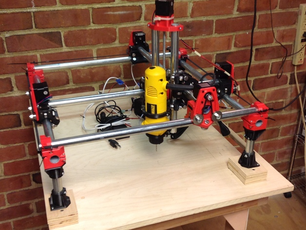
Ooh…final question…does it matter which direction the Z axis is pointed in relation to X0 Y0?

The thingiverse picture kinda has the machine at a diagonal, so I’m not entirely sure which is X and which is Y.

If the left hand (not pictured) corner block would be 0,0 - then that’s how mine is.
If the lowest corner is 0,0, then the tool is pointed in and towards 0,0 - then maybe I need to turn my assembly around.

You found the problem. You should not be able to feel the stepper tick. I ticks 3200 per revolution, should feel buttery smooth.

So now as said before, its either the driver voltage, or loose wire.

X is left to right Y is front to back, typically.

Yeah, I know that. :slight_smile:

What I meant was in that particular picture, I couldn’t tell which was X and which was Y.

In this pic:

The tool/mount is on the closer side of X0, Y0…presuming that’s the lower left corner of the picture.

Depending on which way your picture is oriented, it could mean the tool is pointed towards X-max, Y-max. Was wondering if it made a difference in direction?

I’ve got a meter and going to do some motor testing.

Makes no difference.

if you switch the x and y plugs you can narrow down the issue. if the same motor is bad it the wires, if the other motor is bad it’s the driver. take you 2 minutes. Make sure the power is off.

Alan,
I like to have the rear left (in your photo) to be origin/X0Y0 and the front left to be XmaxY0. As Allted says, it does not matter but I am right handed and that orientation makes more sense to me when I am locking down the stock to the spoil board. Also the Y axis rail is not in the way. Also it make sense to rotate your table 90 degrees counterclockwise.

All 4 motors give a little “pulse” when putting a single finger on the pulley/shaft when going at slow steps (75mm/m). So either I’ve got 4 bum motors, or it’s more normal than we think.

I resquared everything, Re-belted, and tightened down things that were loose (motor mounts etc).

The only major thing I did was on the trouble axis I just switched which plug was connected to each end which reversed my X. My pot on the “trouble” axis reads .68/.69, so I think I’m right at good there. I can’t seem to find .7 exactly but I don’t know how much 1/100 of a volt will hurt.

Don’t know what seemed to do it, but things are getting there. A test diagonal today was MUCH better than the other day.
I need to get a “real” table. Right now my table isn’t perfect and wiggles a bit during rapids when the motors whirl up and then come to a stop. That doesn’t affect the feed rate @ 75mm/m nearly as much as running some 4000mm/m or more during rapids.

But another thing I just need to tighten up and make 100% perfect.

I think another issue is going to be smoke and probably doing an air-assist or at least getting the laser mount it’s own fan. I don’t know why I didn’t include that when I bought, but will end up finding a small fan and maybe printing an air assist mount down the line. Having even a small fan blowing onto the workpiece seemed to help a little.

Going to do some further test objects as I get things dialed in to precisely how I need it.


So, I’m thinking a LOT of this might be a combination of the JTech Plugin and/or Repetier-Host.

First picture is something I cut last night. It missed some lines, elsewhere on there is a straight line that isn’t in my image (but is in the gcode previewer in Repetier).

I set it in inkscape to do 42mm by 15 mm…and it came out somewhere near 21 inches by 8 inches. Can post the gcode later if anyone wants to take a look. Some I attribute to lack of smoke clearing. When I have a fan turned on blowing onto the laser, it does much better. But my fan doesn’t provide 21 inches of coverage so some spots the smoke lingered and the laser got caught in it. Better fan connected to the laser mount absolutely needed!

If anyone has a laser, can you send me some Repetier-ready gcode to draw a simple object or two (circle, triange, square) that are “known” to be pretty dialed in and perfect on the gcode end?

Heck, I can add the laser part myself. Right now my only other gcode generator is Easel, which is set up more for the XCarve and GRBL shields.

I just need to find out how well I can run something that is known to be perfect, then will work on how to get some better gcode outside of the JTech plugin (which is also kinda intended for their own GRBL firmware they developed.

I think it’s getting MUCH better. That one little leg on the left that looks a little light marked was not having the fan pointed towards the workspace and smoke issues.

I think a good part of the issues was just getting everything properly squared, belts and bolts to the right tightness, some smoke work…and removing Inkscape and the JTECH plugin from the equation.

I can go into it another time, probably as I start talking more about using laser with MPCNC…but the generated JTECH gcode was really wonky. I think it was designed specifically for their version of GRBL. At some point, I may replace the board with a more GRBL ready one like the X-Carve per another user’s suggested…or just build another one and buy the printer head and proper mount (why oh why did I select the router tool mount when I own a CNC machine with a router!!!) so I can print parts for the second machine.

What do you guys think? Does it look ready for action now?

Looking good. I received my laser today. How do you have yours mounted?

I had a friend print up one of the jtech/MPCNC mounts on thingiverse.

Laser Mount