I went to Home Despot and they didn’t have the 1/2" square tube, but they did have some C channel. So I am just gonna try hard and not look at it from the bottom. I think this will work fine. It is plenty stiff. It was $13 with tax, for anyone who’s keeping track. I haven’t measured it with the calipers yet, but lucky for me, I have the CAD if I need to change it slightly.
Hey @stewart. I really like the design. LOVE the OnShape document. I made a copy and will probably make a build of my own in the next few months.
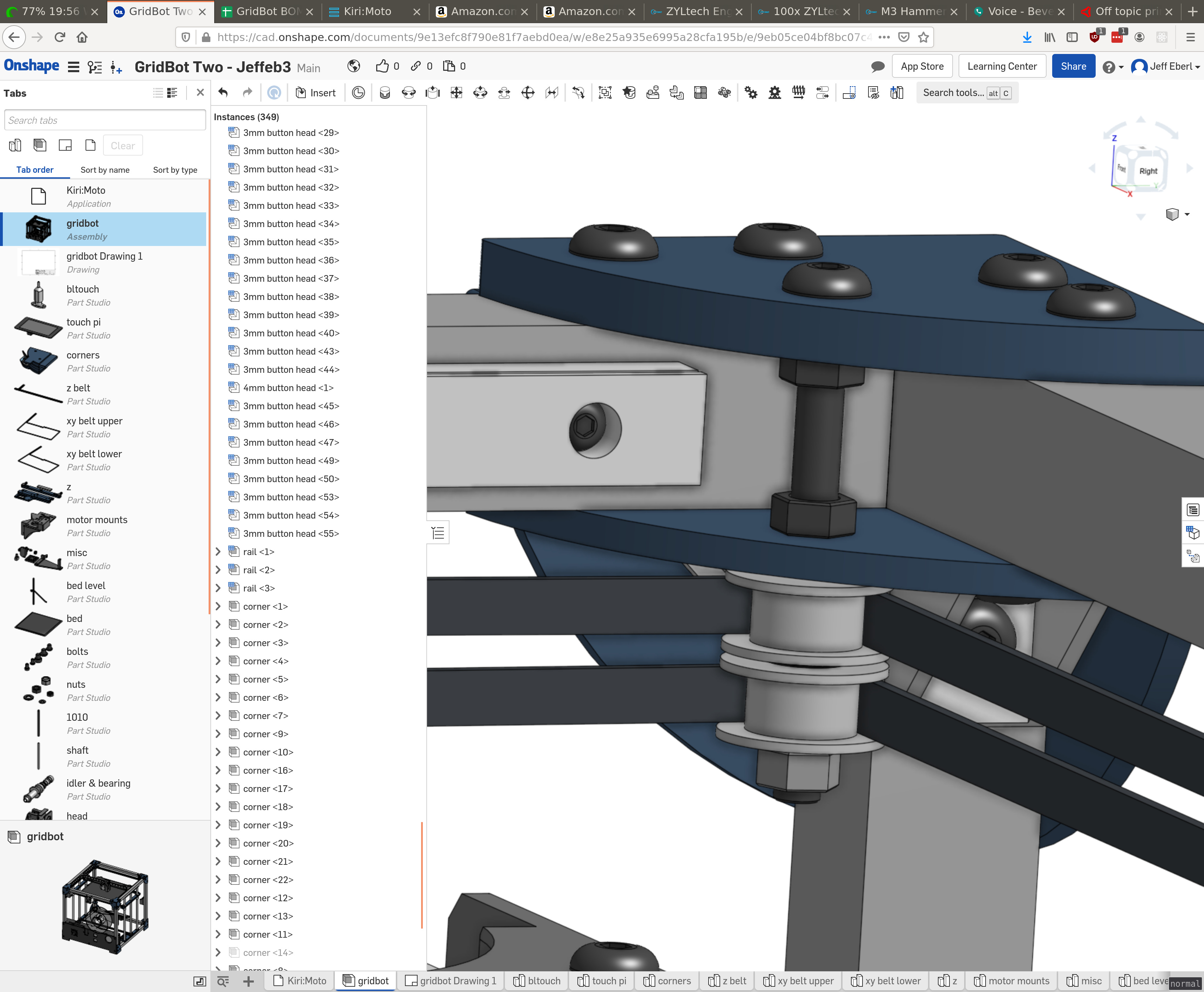
I have an OnShape user tip that you may find helpful. Instead of adding hundreds of parts into a single assembly and connecting each one individually. You could create smaller sub assemblies with many repeated parts. Then add/insert the sub assembly into a larger assembly one or more times. For example: The corner pieces with the bolts could be a starting assembly. 9 Bolts, plus one corner piece. Get that all attached then create another assembly for the box frame. It would have the 2020 extrusions and 8x of the corner assemblies. That way each sub-assembly could be reused as often as needed. This makes it SUPER easy to update and maintain. If you needed to change the length of the bolts you would have to update about 50 pieces in your current assembly. But if you had them in sub assemblies you would only need to replace 9. Hope that makes sense. It might be difficult to explain in text.
Here is one of my files that uses sub assemblies if you want an example of what I mean. Look in the Assemblies folder. The full assembly just uses the sub assemblies.
@mordiev great tips. I think the document as it stands represents a design that evolved and changed significantly over the years. If (or when) I rebuild it from scratch, I will use the techniques you describe.
So far, I have shied away from assemblies at all. I see now that I need to really embrace them a lot more. I should probably spend some time watching some onshape tutorials. I watched a few when I started to get some simple things done, but then as soon as I was dangerous, I stopped. Now I see that even though I can generally do what I want, I could be doing a lot more if I learn some more.
yes, it provides a consistent offset from the back of the printer so that the z axis is aligned perfectly. use top and bottom. can be printed quickly and light. it isn’t attached to the printer.
OK. I’m not finding that on the drawing (95mm doesn’t seem to be a measurement to the 2020 or the angle bracket). There is also the electronics on the bottom. Should that be 95mm from the rear of the 2020, the front of the 2020, or the front of the angle brackets?
Unless I’m missing it, I don’t see the part fan on the BOM either. It looks like it will accept a 40mm fan, but you’ve also drawn a 30mm fan adaptor? What does the chef recommend?
I’m almost done printing the bottom right z. This has warped a little and pulled the spring steel sheet up in the lower left corner. The bottom left Z just barely fits, wish me luck! I will be making the Z middles on the CNC. Should be an interesting aesthetic. They won’t fit on my existing printer.
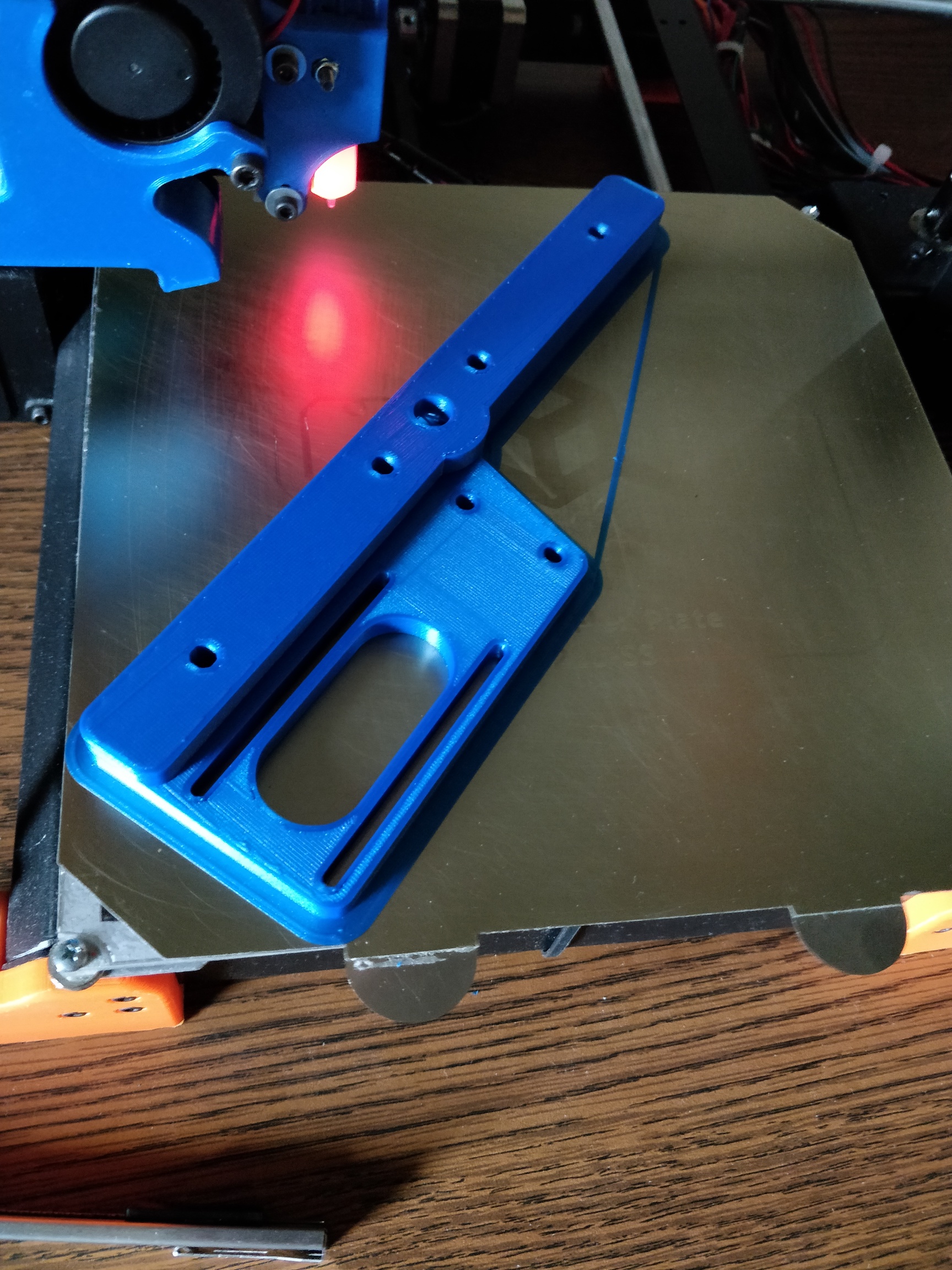
The cross bar spacers are soo close. If I remove my bltouch I can fit them, but I can’t print them on this bed without the bltouch. I am considering just skipping them until I can print them on the gridbot. Printers should be able to take care of themselves, right?
It looks great. I will have to drag it outside on a cloudy day and see if I can get some better photos. The phone or this lighting isn’t doing it justice. The only problem is, I will always have to keep some on hand, because I can’t mix and match with this.
@stewart, do you have the top, front, inside corner brackets installed? I must have bigger brackets (mine are from zyltech). It looks like the long M5 is going to collide with them. I have a bunch extra, and an angle grinder. So I could try to cut two out. I was thinking I might just omit them though, since I have plastic above and below keeping that corner square
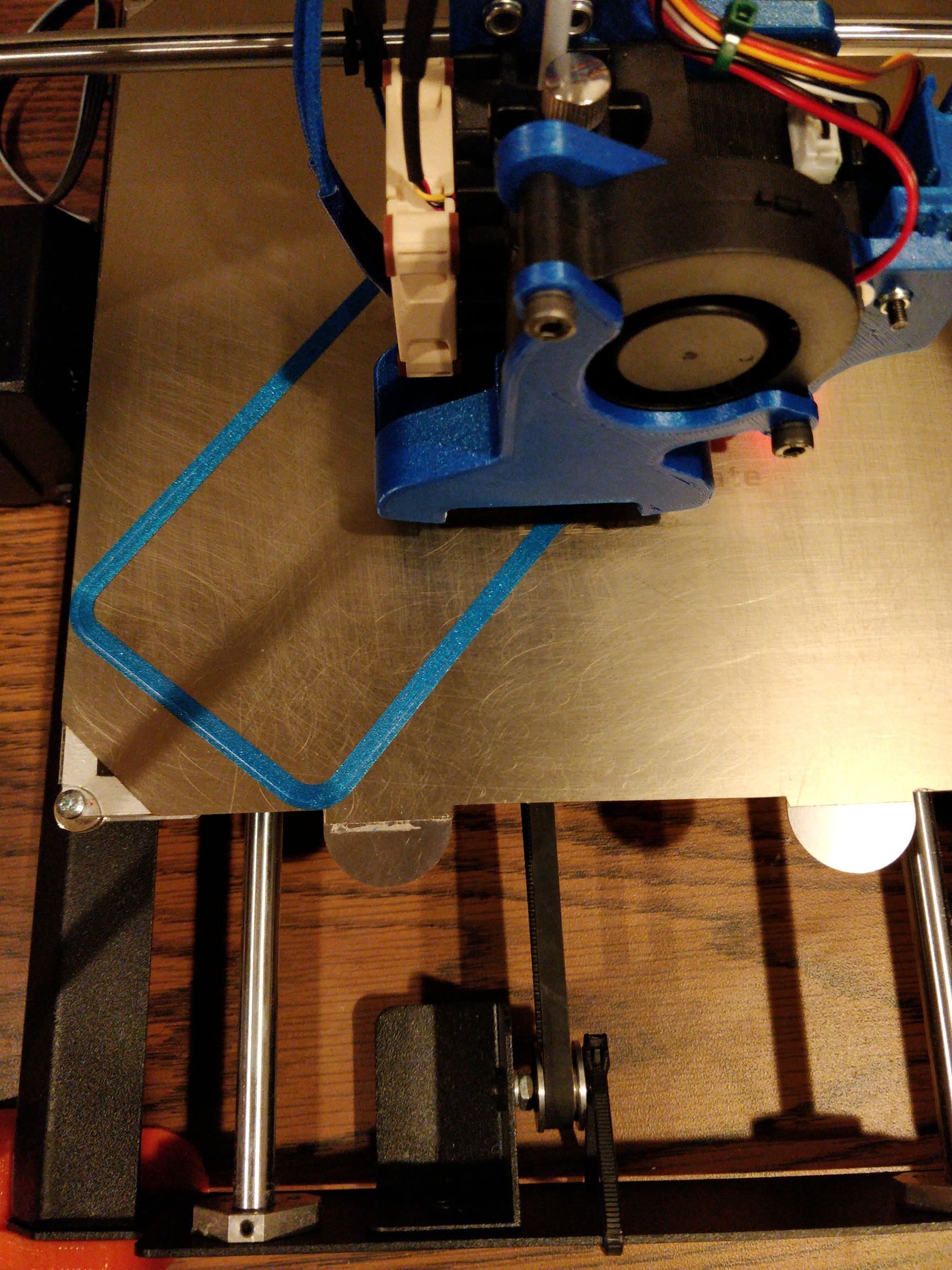
If I was to print these bottom pieces again, I would make a few small adjustments since I am using a printer and not the laser. I would make the overhang/bearing holder on the left a little easier to print. I would also make the bearing holes a tad shorter, since they are a bit taller than the bearings and are rubbing against the pulleys. A moment with a debur tool fixed it after the fact. (I’m happy with it, but someone looking at this in the future might care).
For some reason, the three linear rails are all coming on different days. I have two so far. . I’m excited to build the corexy part of it.
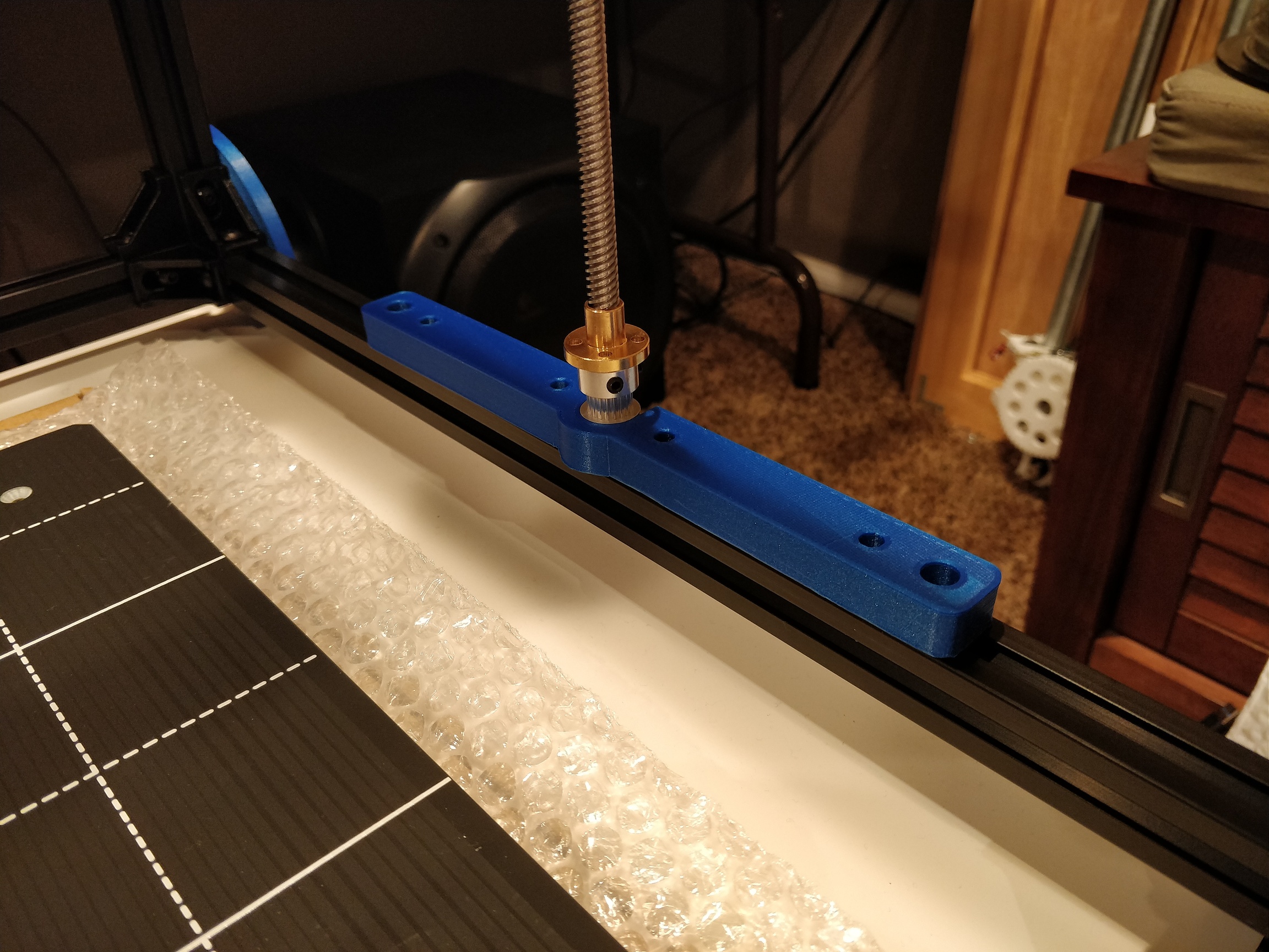
those provide a critical function of providing two anchoring points for the m5 thru bolt onto which the idlers sit. these two nuts need a surface to tighten against and this makes your XY belts rigid. otherwise the long m5 “post” will flex.
I’m not 100% sure we are talking about the same thing. I plan on installing the corner plates, top and bottom. But the black steel brackets I have are larger, and interfere with that long bolt. So I’m suggesting I could leave out that black steel piece:
ah, I see. you tighten the nut against the plate (opposite directions), so the angle bracket doesn’t play a part there. having a metal angle piece is better, obviously. I would advocate getting the one in the BOM rather than going at it with an angle grinder. it’s hidden, anyway so you won’t notice it’s not black. I haven’t tried 3D printed angle pieces. could be ok.
yep. waaay back. it was one of the 5 CF filaments I did head to head tests with. I don’t recall exactly how well it fared. but for my purposes, the Ziro still won out.
First try, oops, I made the holes for the 1/2" channel full depth. The flanged bearing blocks and the leadscrew nut are ok though. I just touched the screw locations with a 2mm deep hole. I’ll finish those on the drill press.
I am cutting this pretty deep. 6.5mm/pass at 6mm/s. Takes about 6 mins each. It isn’t perfect, but it is pretty close, and the results are within sanding.
I’m sitting here, waiting for the corrected job to finish.


 . I’m excited to build the corexy part of it.
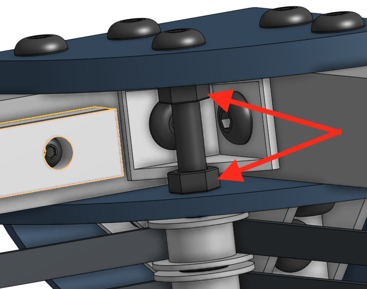
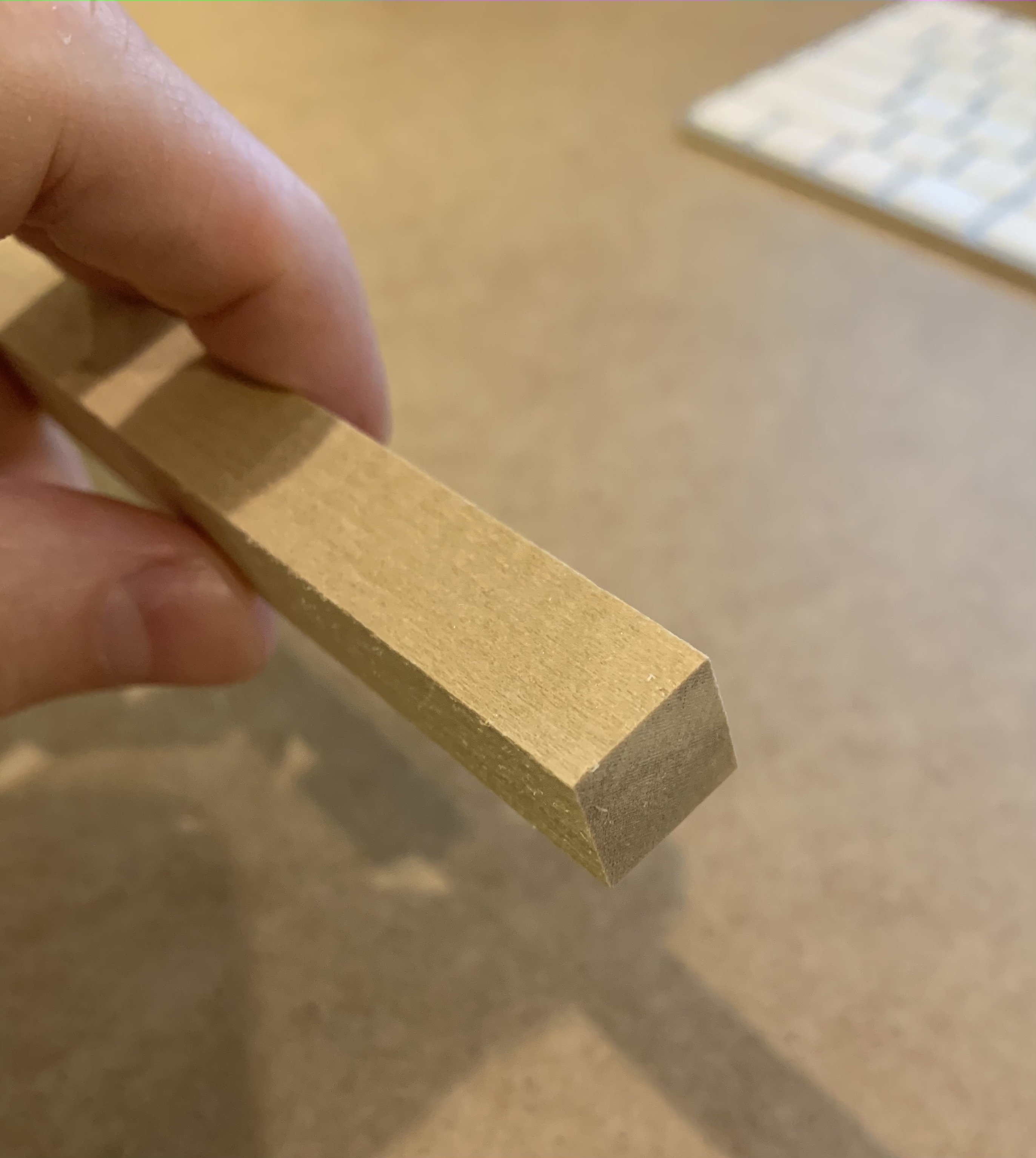
 ! Half inch baltic birch ply. It should look really nice with some poly on it.
