Jono's MPCNC-IE Build in NZ

I’m in the process of printing the parts for a MPCNC build in Auckland, New Zealand.

I’m printing in PLA from DiamondAge through a Mendel90 printer. I’m using 0.3mm layers and Ryan’s recommended settings everywhere else. I’ll be using a the normal hardware kit

I printed the 4 corner blocks as one plate earlier and it took around 31 hours. I started it on a Sunday evening right before I went to bed and it was still going when I left for work on Tuesday!

I’ve been having particular trouble sourcing any 25mm tube, but I’ve found some 3mm wall aluminium tube available from a local supplier. 3dTI has used the same tube but anodised, so that’s the current plan.

Total goal for the project is to have a usable cutting area of around 610x610x150 so that in theory I can cut stuff out of pieces of 1200x600 ply or MDF that are readily available locally and easy to transport. This will likely make the table slightly more irritating to construct as the 600x600 stock can’t be used to make the table, but so be it.

For a spindle I’d like something that can work with Aluminium, even if only roughly and slowly for very ‘functional’ items, so I’ve ordered a 500W Chinese air cooled spindle with power supply/speed control. Alternative choices are somewhat limited here, given that we get different versions of most laminate trimmers etc. but once the machine is constructed I’ll have a better idea of what the weight/power requirements are.

Wow. I thought i almost was the only one with a Meldel90. Mine is about 3years old and still going strong. I have been printing for about 5days now. Think I am at about 75% of the printing

Sounds like you are on the right track. You have definitely done your research. I can’t say for sure how the aluminum will do, I have wanted to try some thick walled aluminum but I don’t have a good supplier locally. Hopefully the bearings actually work harden the surface relativity fast and you hopefully only need to snug things up once. Keep us in the loop, more rail options would be nice.

Nice, Andreas! I think there must be quite a few of them in the wild because I’ve met quite a few people who have heard of them. Just over the past couple of weeks I’ve been helping someone who missed out on the last batch of kits and ended up with something a bit cheaper/crappier. I hope yours has been as reliable and bombproof as mine. I think mine is around 2.5 years old now (ordered end of 2013) and I’m not actually sure how much filament I’ve put through it. Probably around the 10kg mark, but mostly as large prints.

I like the reel holder. I’m in a pretty hot/humid part of the world so I keep the reels in a big plastic bin, each in their original bags with dessicant, etc. I’ve never had any change dimension on me noticeably, so that’s obviously working out ok. What’s the tape you’re using on the bed? I’ve never had to use anything other than bare glass for the PLA I’m using and glass + ABS juice for printing with ABS the few times I’ve done it.

Ryan: I’ll let you know. Still haven’t got the tube, but I might be able to pick it up tomorrow. Shipping was going to be half the price of the tube. Was also carless over the last weekend due to mechanics ordering the wrong parts in. I’ve transported some odd things by motorbike but a pair of 2.5m long aluminium extrusions isn’t about to be on that list!

As for the printing progress, the middle Z piece was the first decent part I had ever printed with support and it came out beautifully. I was actually quite impressed. I’d printed a few basic test objects before but the inability to remove the support cleanly etc. just led me to decide that it was better to just bridge and be careful with my part design. I’ve never run into a situation where I absolutely needed it, thankfully. I don’t know what other people’s experience with PLA and support was like, but Slic3r worked perfectly.

The parts had the support come off cleanly with a little encouragement from a box cutter and steel rule as a wedge. Nowhere near as easy as the peelable support on our Up Box or Up Mini work printers, but plenty easy enough that I’ll use it in the future without worry.

Anodizing the aluminum rails before assembly would get them hard enough to resist wear. Seems like it’s just better to use something harder though.

I agree that something harder would probably be better, but 25mm steel tube is completely impossible to find here. It gets tricky to verify, as well, as I’ve had several companies tell me they have 25mm but when checked it was 25.4mm OD. There is a thread about this ‘Australian Tube Options’ in the Assembly section.

I also agree with respect to the wear resistance, but I’m wondering if flat spots might end up forming due to deformation of the underlying material, rather than wear itself. The anodized layer is only a few um thick (12.5um on the regular anodizing that I’ll be going with, but potentially 25-50um for a lot more money). Obviously, that layer isn’t strong enough to have any structure by itself, so it’s still reliant on the base material to provide the overall strength (in the same way that you couldn’t use a tube made out of tinfoil, no matter how hard it’s surface was). I guess it will act to spread the load somewhat (after all, it must be somewhat stronger than the underlying aluminium) but my assumption is that this effect has limits.

My hypothesis is that with enough time and pressure, this base material would cold flow until there are flat spots on the rails. What I don’t know is how much actual force the plastic pieces exert through the bearings etc. I assume that the round tube will eventually end up with a flat spot that is wide enough that the force exerted no longer causes it to deform plastically. It’s all just a question of how wide that flat spot isGiven the lack of options here, it looks like I’m simply going to have to try it and see! I suspect this could be directly measured using something along the lines of one of the standard indentation type hardness tests.

A quick google has just shown that it seems that hardness testing of anodized aluminium is indeed tricky in this regard as the macroindentation hardness tests (high force, large deformation) tend to reveal more about the underlying material hardness rather than the surface hardness by breaking through the oxide layer. http://www.practicalmachinist.com/vb/general/anodizing-hardness-202779/ post #4 has a comment on it.

Have finished all the big prints now, just about to start one final pass to finish off all the little pieces.

Image shows it all arranged on the desk. Out of sight are the translucent orange pieces for the feet.

In order to use my filament relatively evenly, I’ve printed it all in varying colours on pretty much a whim. With the DiamondAge filament, I’ve never noticed any preference for different settings with the different colours and they all seem to print the same. The pieces are colour coded as to where they’re being used, apart from the red Roller Locks, which I might re-print in sapphire just to match the Roller F parts.

Also picked up 3x 2.5m lengths of 25mm diameter, 3mm wall Aluminium. $120NZ incl GST all up from Ulrich Aluminium, die number UA1248. This will give me enough for 6 lengths at 800mm for the frame rails, one length at 800mm that will get cut up for the Z rails and plenty spare for the legs. I’m going to end up with probably ~1.5m spare, but that’s not such a bad thing, so I’ll call the aluminium cost $100, even.

I’ve confirmed again with Anodising Industries in Onehunga that 7-8 pieces of up to 800mm long with regular anodising will just be their basic minimum job cost of $50 incl GST. For $60 they’ll do it as black. If there are pieces that are shorter then that will require setting up a 2nd jig which will make it $80-90ish so the current plan is to have one extra piece the same length as the X/Y pieces and then cut it down post anodising. The guy said that because it sounds like an easy job to set up, they might be able to run it as ‘Marine’ anodising for the same price, which would result in a thicker surface finish, I believe. The main reason to avoid >800mm long parts is that this company can’t handle them , which leaves me with the other companies that were charging pretty much double.

The downside of that is that 800mm lengths leave me short of my goal of 610mm cut width. Now that I’ve got the tube, it looks a lot flimsier than I original expected so I doubt the 900x900 machine required to run a >600mm cutting area would actually be a good idea. I figure I’ll stick with 800mm long rods and I can always shrink the machine later, if it doesn’t look like it will be rigid enough for what I want to do.

So assuming I can scavenge materials for an adequate table, the current total cost is:
MPCNC Hardware Kit + Shipping = NZ$490.65
Aluminium Tube + Anodising = NZ$150
Printer Filament, ~1.5kg = NZ$85
500W Air Cooled Spindle + PSU + Collets = NZ$188.46

Total: NZ$915 (~US$600)

So a bit more than I was expecting to spend at the start of this, but if you compare it side-by-side with no spindle, still about 1/3 the price of a Shapeoko.

After a couple of weeks of being particularly busy and getting involved in a few other events, I finally found the time to drop the parts off to get anodized.

Given the minimum charge on the order, they’ve said they’ll try get it done in 25u ‘Marine’ anodizing, so should be a little thicker.

Unfortunately, the tubes were originally chocked in place in the car but over the week it took to get things sorted, they started shifting at some point and a few of the tubes have picked up some extra scuffs etc. Hopefully that shouldn’t be too much of an issue. I’m assuming the cold working of the material will likely smooth out any rough spots, anyway.

In addition, the 500W spindle arrived a few days ago. It looks pretty good and there’s no visible play/runout in the spindle when turned by hand. I haven’t clamped it up to check with a DTI yet but that’s on the ‘todo’ list. Given some of the things I’ve seen in other threads, it’s often the machining on the taper for the ER collet or the collet itself that lets the spindles down with respect to runout. I figure just chucking a new twist drill and putting the DTI on the shank where it comes out of the collet is probably enough to check that to within my likely requirements.

I’m leaving out printing a few parts (spindle mount, etc.) until I’ve got a better idea of how I want to mount it. The fan at the top of the motor looks like it might need a bit of extra clearance than the motor itself, so I want to check that out on the actual machine.

The other thing of note is that I forgot to check the GT2 belt for total length with the machine. It looks like I’m going to be short a bit, so that’ll result in another quick order to get some of that. I’ve got another little project (cartridge case annealer) that is currently in the works which could use some, so I’ll do a bit more work on that and then consolidate.

Well, a bit over 4 years later and things have moved on somewhat.

After getting a bit stuck, a bit sidetracked, breaking my printer, running into bed adhesion problems and a few other things, this project got put on the backburner.

As a COVID lockdown project, I decided to take another pass at getting this thing up and running.

In trying to figure out where I had gotten up to, I noticed there were a few things that had changed. The multiple sets of parts customised for different tube sizes is an awesome development which would have saved me a ton of time when I started. The newer Burly parts were also pretty enticing, as some utilitarian aluminium machining was always something I was hoping to be able to achieve.

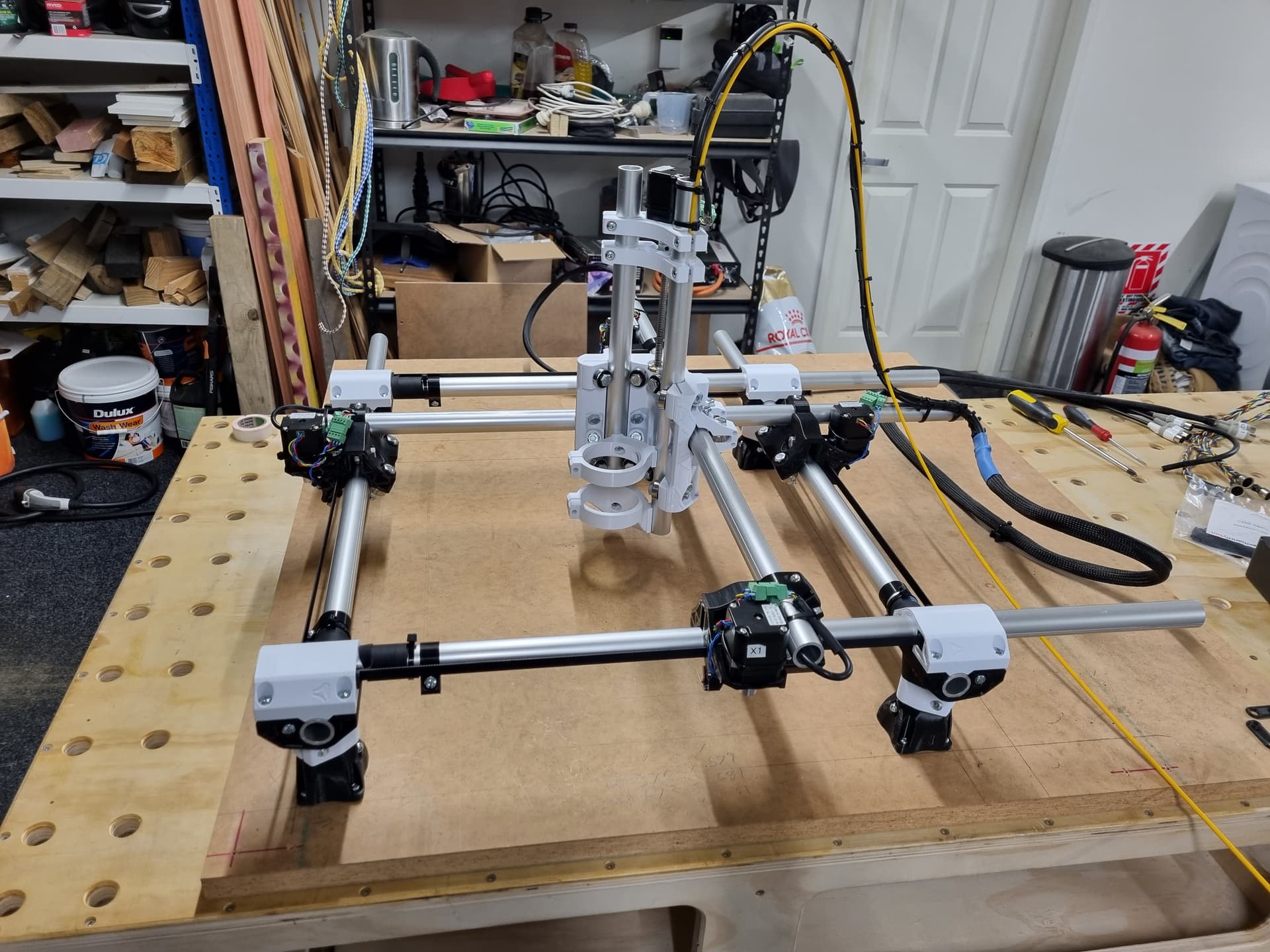
So, with that in mind, I set out and reprinted all the parts and started going through the assembly process a couple of months ago. I got most of the way there (everything assembled and movable by hand) but as my build is from one of the original kits, it needed some extra parts subbed in. I went straight for the dual endstop version so that necessitated picking up some more stepper drivers which got delayed somewhat. The T8 leadscrew arrived earlier this week after 4 months in transit (!) and I was finally able to have all 3 axes moving together. The T8 leadscrew I was sent is the wrong pitch (4mm/rev instead of 8mm/rev) but I can’t see how that would cause an issue.
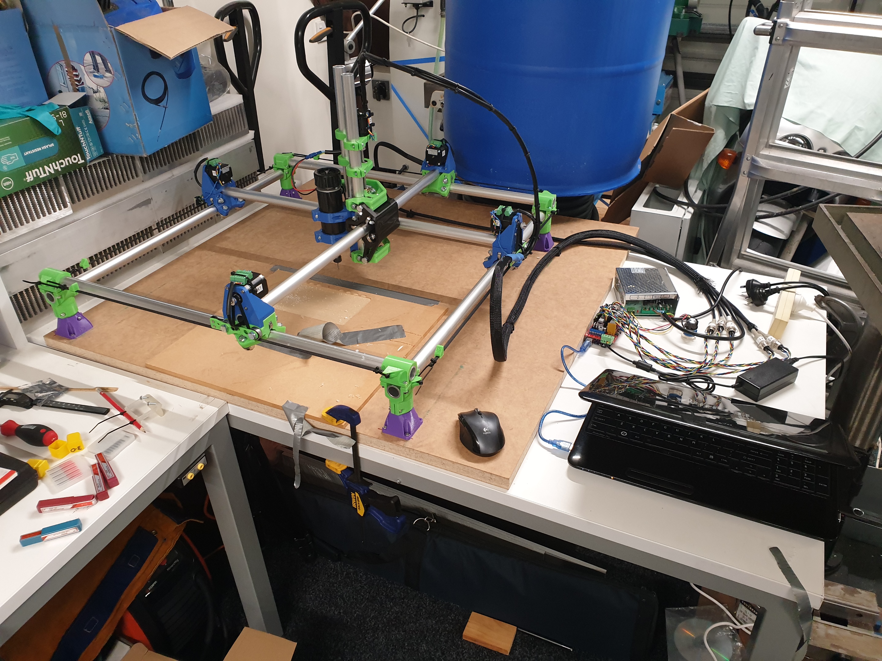
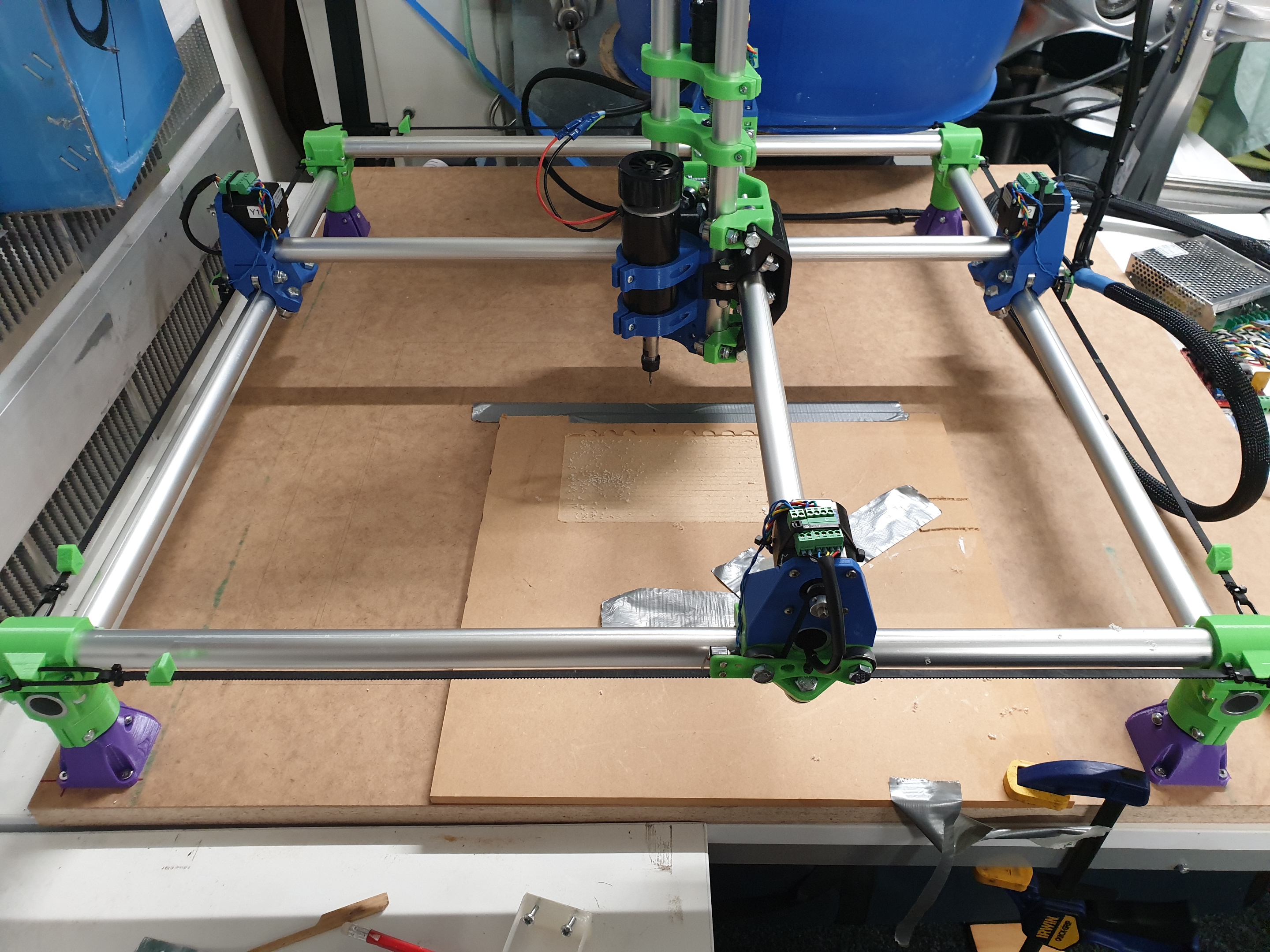
So, my build is:
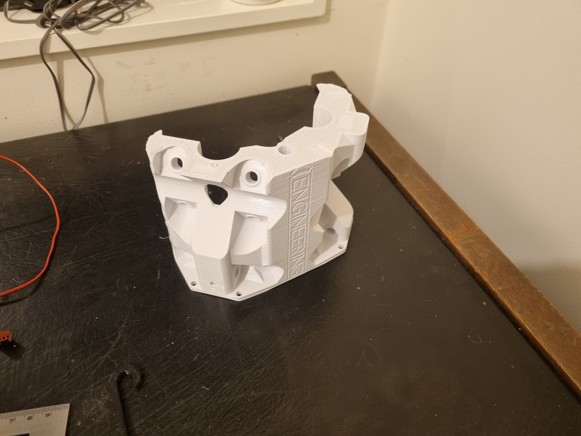
3D printed parts: Burly 25mm dual endstop, DiamondAge PLA printed on a Mendel 90
Rails: 25mm OD, 3mm wall aluminium, 25um ‘marine’ anodized, 600mm lengths.
Motors: As supplied in the original kit
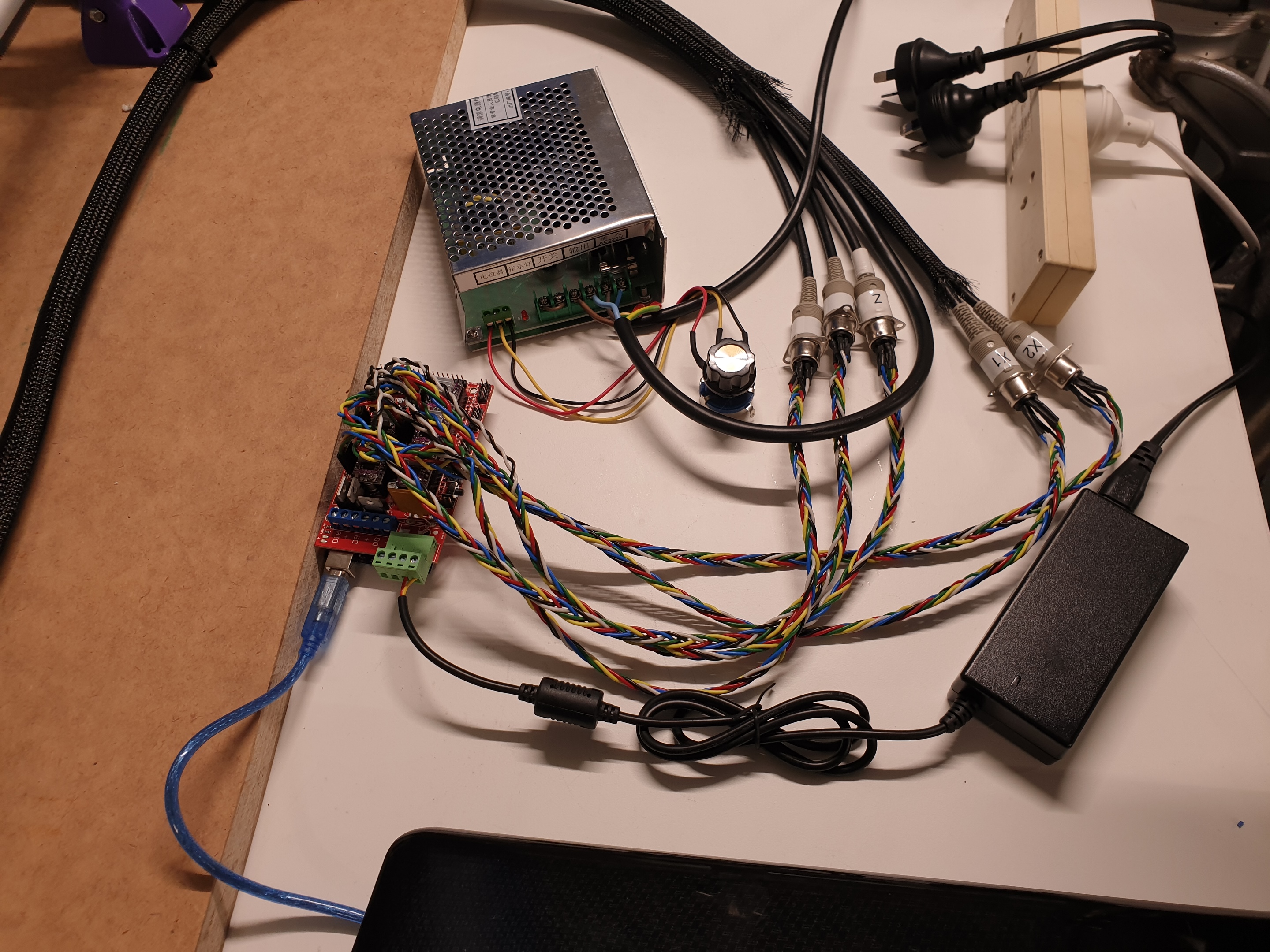
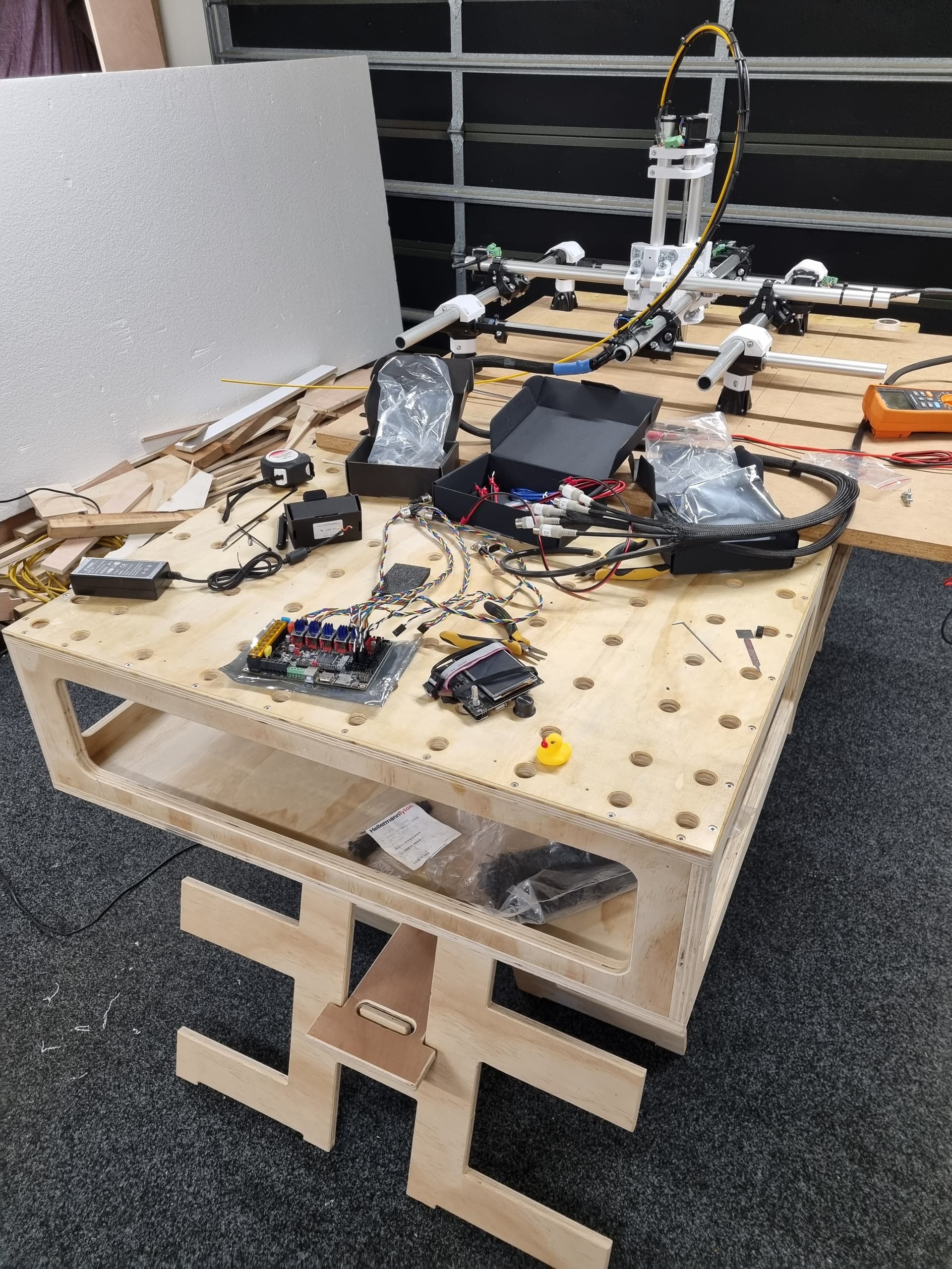
Control: RAMPS with DRV8825 drivers
Spindle: 500W air cooled AliExpress ER spindle

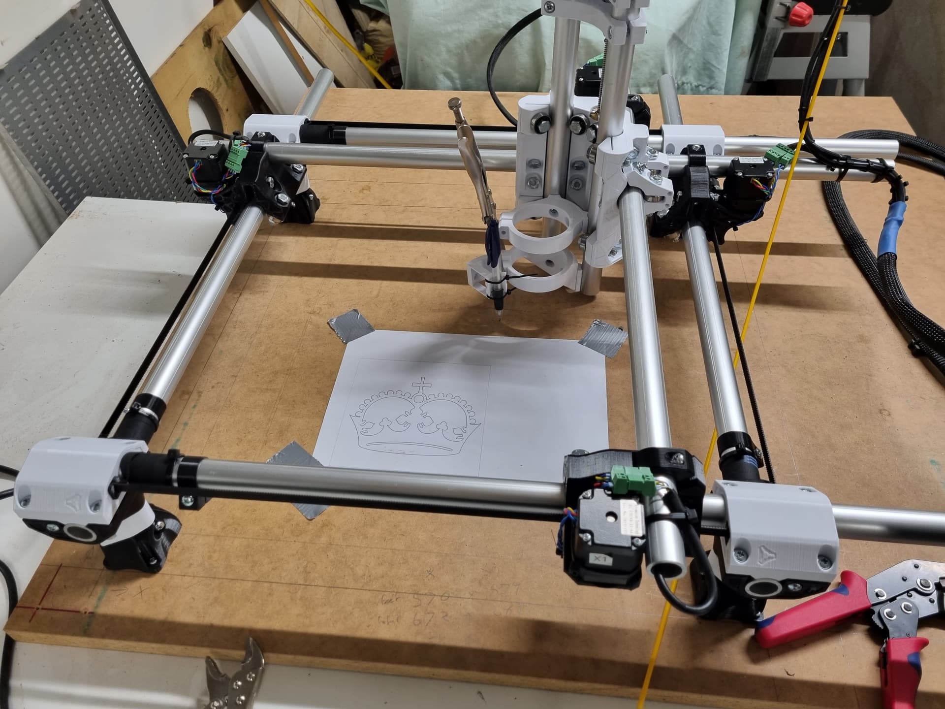
At the moment, I’ve got the height set at the minimum as that seemed to be the easiest option until I’ve had a bit of a play around. I’ve deliberately left the Z axis rails long and I have extra aluminium left over for the legs so I can easily adjust it all later.

Everything is wired up and moving together. I needed to add about 1mm of adjustment for the machine to square up, which was easy enough. Using the pen mount with a sharpened pencil directly onto my wooden bed, I get the diagonals of a 530mm square identical within half a mm, which is well beyond anything I’ll likely need.

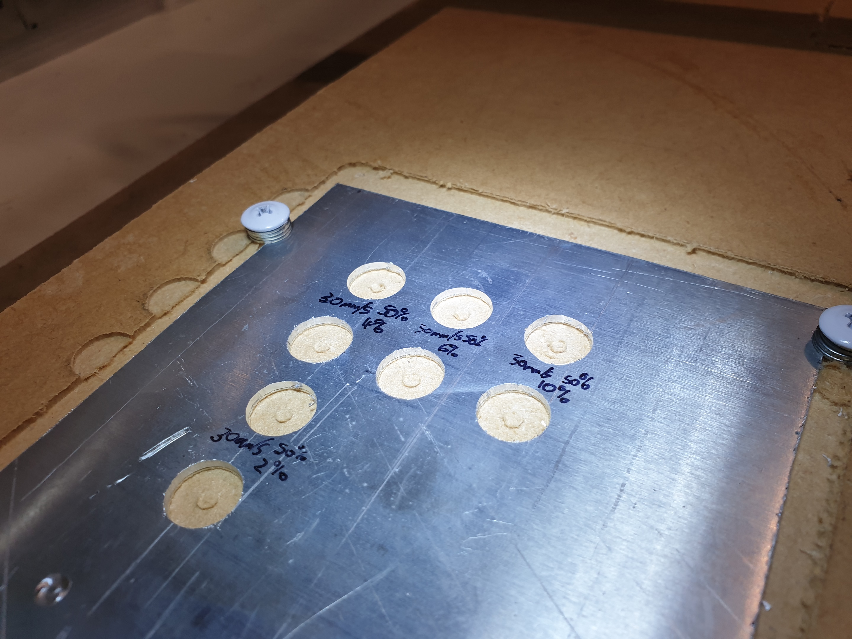
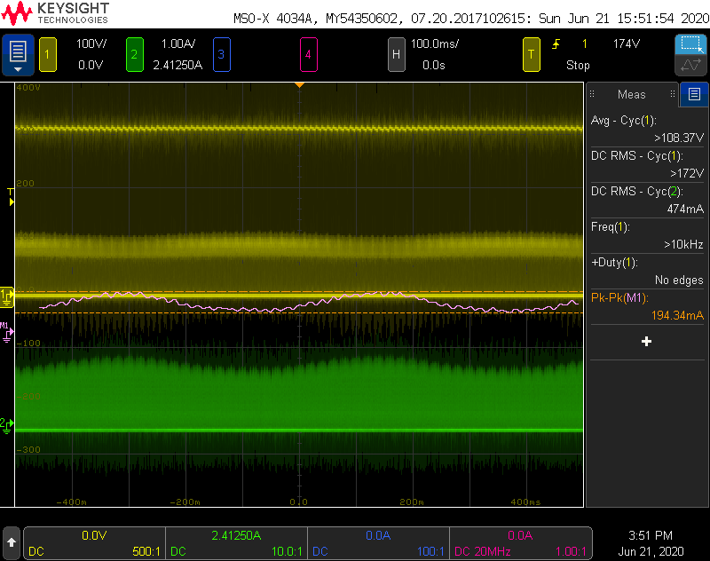
First task for the machine was to modify the lid of an ABS enclosure for a piece of test equipment I was making. So did some playing with ESTLCAM, some air cutting, a test cut in MDF, pocketed the MDF to give a nice reference for squaring the lid to, taped the lid down and ran the job. No problems, job done. Pretty happy so far and looking forward to playing with it some more.

Still a couple of things to sort out: enclosure for the electronics, spindle motor control, perhaps a dust shoe etc. but I’m calling it done enough for the moment.

Original kit order date: 21st Jan, 2016
First chips date: 19 Jun, 2020
4 years, 5 months. Yikes.


6 Likes

I think that describes every project I have ever done.

1 Like

Hahaha, fair enough.

For the most part, it has been a mixed bag for me, project completion wise. My 3D printer assembly was pretty straight line but largely that was because all the parts were present. I’ve also recently put together a Liteplacer pick and place setup for my business which was also pretty much linear start to finish, although there are lots of upgrades and extras that it needs which have the potential to get sidetracked.

Either way, now I have to figure out what I’m going to do next to push my familiarity and understanding of the machine and toolchain. One thing I’d quite like to do is figure out an elegant way of working with larger objects. Specifically, I have a couple more projects where I’d like to be able to machine the sides/ends of existing ABS/polycarbonate/FRP type enclosures for them. Currently, I think the most obvious option seems to be to creating a cutout in the bed so that the workpiece can stick through from the bottom. The original plan was to drill a bunch of holes for claw nuts, but a hole somewhere might make that a little awkward. Potentially, I could pocket the entire bed which would allow spoil boards to be dropped in which could themselves contain the nuts. The bed is 30mm triboard so that might get a little ugly, but it would be if I used it as sacrificial anyway…

Great to see a fellow New Zealander on here! No one else really understands just how few hardware options we have, and just how expensive everything is…

For my MPCNC build I decided to go with the ‘J-Burly’ option. I use 25.4 mm stainless tubing, and imperial screws. Finding 25.4 mm tube wasn’t that hard, it’s a standard size that most metal tube suppliers have. Mitre 10 stocks a pretty good range of imperial screws and nuts as well.

As for the spindle, I’m using a 600 W Makita router (which I luckily managed to find on trademe for $90!). It has a 1/4" collet, and I’ve been able to machine aluminium with it quite nicely using single-flute carbide tools. Although a big downside of the fixed 1/4" collet is that you have very limited selection of metal cutters available in NZ. However, McMaster-Carr has an excellent online selection, if you are fine with the shipping fees.

As Ryan always points out, for aluminium, stiffness is key, and my machine is quite small (270 x 270 x 70 mm) and, as mentioned, I use thick stainless tubing. Have you tried doing any alu on your machine? What do the results look like?

I’d be happy to show you my build! :slight_smile:

Cheers

1 Like

Hey, great to see other kiwis, for sure!

Yeah, access to stuff here can be pretty limited , but it seems to be getting better somewhat. There are actually local people that stock cheap linear motion stuff now, which is nice.

Nice, the 25.4mm stainless tube is what I would have done if there was a 25.4mm build option when I started out. I’m not sure when you built yours, but relatively recently if you went for the ‘Burly’ option right out of the gate. I’m not even sure what version I originally printed back in 2016, but I think it was the first one released to the wild. I’m not sure how the naming scheme has gone, but it may have been before the 525. Anyway, the difficult part was that the design was only available for 25mm tube, and there was a lot of speculation about whether 25.4mm tube was going to break things or cause issues with the rails being too tight.

That’s a sweet deal on the router. Are there any solutions out there for the fixed collet? I’ve actually been pretty happy with the AliExpress spindle so far. It has pretty decent runout and it’s nice having ER11 collets for 3mm, 1/4", 1/8" etc. It also means I can use my existing spotting drills which could be pretty useful. Would be neat to have a bit of a play with some stub drills, too. So yeah, that’s not a terrible option that’s out there, at least. I’d like to pick up a router at some point and try it out to compare, but I don’t think I’m going to run into issues due to the spindle power or anything.

In case of the aluminium, it’s more that it’s a goal which can be relatively slow and would likely be for cutting out sheet. Original plan was for some rack panels/blanking plates. I’ve got a bunch of aluminium stock that got cut down to 19" rack panel sizes and anodized. Being able to pocket that, even if slowly, would make life a lot easier for some test equipment setup stuff. It’ll simply be a case of trying it, seeing what happens and trying to adjust accordingly. It doesn’t need to be a particularly good looking part or anything, I’m normally aiming for function over form with most of the stuff I’m doing!

Worst case, I’ll reprint for 25.4mm tube, shrink the machine and just plan to make an LR or something :slight_smile:

Do you have a thread on your build anywhere?

I got my 25.4 mm tube from Wakefield metals, they even have a catalog.

I doubt it’s worth it for you to go from 25 mm to 25.4 mm, and at any rate, alu has fairly high stiffness/weight ratio and you’re using 3 mm thickness so my intuitive guess is that it should be more than adequate. The main thing I’m curious about is the effect of the large Z axis, as Ryan keeps emphasizing a short z axis is desirable.

That’s a sweet deal on the router. Are there any solutions out there for the fixed collet?

Not really haha, if I were to do this again I would definitely go for a 1.5 kW spindle with non-fixed collet size. But for now this suits my purpose.

I just posted a photo of my build here.

Yeah, I’ve dealt with Wakefield before plenty through work.

I can’t remember the calculations I did for stiffness, but the 3mm aluminium was in the ballpark of 1/2 compared to 1.6mm wall steel. So that’s twice the deflection based on material choice alone. Given that deflection is relative to the cube of length, potentially 8x higher with the machine doubled in size.

Looks like we probably both have the same Z range.

I assume that a lot of that comes down to where the cut occurs, though, so worst case I’ll start in the corners of the bed with the workpiece elevated and see what happens…

1 Like

Aluminium testing time!

That discussion got me curious, so I went downstairs and had a play around with a 1.5mm thick scrap of what I think might be 5051, but I’d need to check back on what I ordered.

So I set up with a 3mm single flute carbide end mill, max spindle speed (12krpm), trochoidal milling path with 50% extra width. I put a 25mm thick piece of plywood under the MDF I was using as a spoil board which got the piece to within 5mm of the tool at max Z height on my machine.

I cut half a dozen 12mm circular pockets, just because that’s something similar to what I’ll likely need to do in aly sheet (holes for shrouded banana sockets).

Got pretty good results with 2%, 4% and 6% stepover. 10% started to look a little different, so that might be the limit of where I’m at for the moment.


Cut both holes twice, once just bare and once with a 0.2mm 30mm/s finishing pass, which seems like it probably could have been a little less aggressive. Overall, I think it was a success. I’d be ok with all the cuts there and I’m pretty happy with the ones after a finish pass. With 10% step over, the thing was moving fast enough for my purposes at the moment, too.

I also hooked up my scope with isolated voltage probes and DC current probe to the spindle input to see what’s going on. Found out that the spindle controller is vastly nastier than I expected. It’s basically just running as a discontinuous buck converter from the rectified ~330V DC bus down


That’s a capture from the middle of one of the 10% stepover troichoidal passes. 30mm/s, 1.5mm DOC, 0.3mm cut. The yellow trace is the applied voltage which averages to about 80V (330V, 25% duty), the green trace is the actual current which is a nasty discontinuous triangle wave and the pink math channel shows the filtered average current. The ripple clearly shows the feed in and out of the cut. The overall capture length is 1 second, and it sounded like the mill was cutting at a bit over 2 passes a second, so that seems right. The peak of the average current during the cut is 200mA more than when it’s not cutting, so that’d be about ~16W of extra power to make the cut. That seems to be within the ballpark of what a spindle power calculator thinks should be the case, so that seems to check out.

Very cool!

The 4% and 2% holes look quite nice.

And yes, 16 W of actual cutting power sounds in the right order of magnitude for your parameters, although you have to take into account that the steppers provide cutting power too.

Where do you buy your aly from, if I may ask? I’m looking for a cheap local source of small aly cuts.

Not sure I’ll be of much help there, I’m afraid. I think all this stuff was probably Ullrich or Mico metals, ordered as full sheets that then got cut down.

But most of those places do cut to order, so you could always visit in person, explain what you’re after and ask if you can rummage through their offcuts.

1 Like

Spent some time earlier in the week with a DTI investigating a few things.

Measuring the Z axis tubes with a digital angle gauge showed them being out by about 0.4 degrees in the XZ plane and being spot on in YZ plane. I tried adjusting the ‘C’ bolts (both top and bottom) for the middle section that are perpendicular to the X axis but going from barely touching the plastic all the way to relatively tight didn’t seem to shift anything appreciably. I’ll take another stab at it later but I suspect I’m failing to comprehend something, and the bottom bolts are awkward enough to get to that I might end up cutting up a cheap ring spanner to get in there.

Separate to that, I had a job that needed a smaller hole than my 3mm end mills, so I grabbed a 2mm drill and collet to try out. As soon as I rotated the spindle I noticed the drill tip was tracing an eccentric path, which was pretty unexpected. I had tested the runout of the spindle when I first got it and found it was in the 0.05-0.1mm range, not great but far from terrible. First thought was the 2mm collet being incorrectly cut, but the 3mm collet and a 3mm drill showed the same issue. Rotating the collet in the bore didn’t change the rotation of the wobble. Putting the DTI on the body of the collet holder and the shaft of the spindle, there’s no appreciable runout. So yeah, unfortunately I guess that can only mean that the taper isn’t cut parallel to the shaft of the spindle. Definitely did not expect that. Won’t be an issue for milling with short end mills, but it basically precludes me from using the machine to drill, as I’d only ever want to do that with small drills anyway.

In the end, just chucked up an engraving tip and manually controlled the mill to spot the drill marks and drilled it by hand. Got the job done and I’ll probably just live with it until it becomes a problem.

Also picked up a Pi 4 and tried out the V1pi image which was nice and easy. Unfortunately, through CNC.js, the performance is kinda horrible. Lots of pauses and jerks with the console sometimes showing a ‘busy, processing’ warning. Seems there are a few options for fixing that and can also try Octoprint (which I’ve been running my 3D printer through for years), but for the moment I’m back to Repetier directly from the laptop.

I found a good deal on a Makita router and I’ve also been using the 18V version for a bunch of stuff so I thought I’d finally pick one up to take a stab at fixing my spindle issues.

At the same time, I decided to use up some remaining 3mm filament by printing the parts to upgrade to a Primo. I also decided to drop the footprint to 300mm x 300mm to stiffen it up a bit. I’ve left the tubes and belts long so I can easily re-configure everything back to ~500mm x 500mm if needed.

Printed all the parts without hassle, except for one particularly unfortunate attempt at the core. I started the ~30 hour print and was discussing it with a friend of mine. They asked what happened if the power went out and I said that the part would be scrapped, but that I wasn’t really worried because in ~10 years of 3D printing I’d never actually lost a part due to a power cut.

Definitely can’t claim that any more.

Using an off-cut of a fibreglass wire pulling rod to keep the Z cable assembly under control.

All in all, probably 3-4 hours to take it all apart and re-assemble it, then another 2 hours of re-crimping everything with JST plugs. Very glad I put the connectors on the steppers and end-stops because it made removing and replacing the wiring loom zero effort. The biggest issue with the crown was finding a working pen and then getting it to stay in the holder. The diagonals of the square around the outside of the crown are within 1mm without any compensation from the dual end-stops.

I’ve mounted the Makita router in it now and made a few basic test cuts in some spare MDF with a properly ruined 1/4" end mill without any drama. Still need to figure out some projects to stretch its capabilities a bit.

These are the same motors, bearings etc. from the original 2016 kit which have seen the printed parts for the original design, then re-printed Burly parts that was when it was finally assembled and made first cuts and now finally evolving it further to a Primo.

The original aluminium rails still look great, I just rotated them so the bearings are all on fresh spots and away it goes.

2 Likes