Hello, Is there a way to connect a joystick or a mpg pulsgenerator to the ramps 1.4 controller for control the motors, homing, etc.?
Joysticks have been added to Rambo boards in two different ways. Ramps boards use the same microcontroller, so in theory, any solution that works on a Rambo board should work on a Ramps board. The only issue is how to get access to the correct pins.
There is built-in support for a joystick in Marlin. It provides just joystick support, but by all accounts, it works well. You can find out more about it here: Joystick managed by Marlin
The second approach is to use a Arduino board to inject g-code for commands. You use one of the serial ports on the Mega board to just send text to Marlin. This is a more flexible but more complex approach. This is the approach used in the topic that Mike references, and there are other implementations out there. While not a joystick, this membrane controller on Thingiverse uses this approach.
It is also possible to connect one of the TFT displays to the Tx and Rx pins on the Uno/Nano (and presumably the Mega although I have not tried that) and use the touch display to drive the CNC router. This approach works on GRBL after tinkering with the icon scripts to mimic GRBL commands, although it appears to be important to select the right TFT display that uses the correct firmware.
https://github.com/makerbase-mks/MKS-TFT/issues/189 however I believe Makerbase have stopped development of this particular firmware due to lack of interest. (and it was pretty dire)
The https://github.com/bigtreetech/BIGTREETECH-TouchScreenFirmware works with Marlin, which runs on a mega2560.
…so many options!
1 Like
Thank you for the info. Just what i need. I have alleady done some arduino programming.
https://youtu.be/DCCcDvBFdvk
Now figure out with pins i need on the ramps board and create a box for it.
The Joystick pins and limits are defined in configuration_adv.h:
/**
* Analog Joystick(s)
*/
//#define JOYSTICK
#if ENABLED(JOYSTICK)
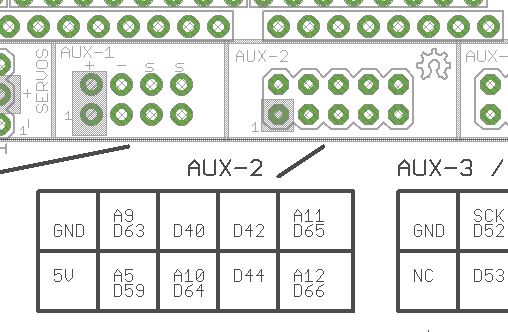
#define JOY_X_PIN 5 // RAMPS: Suggested pin A5 on AUX2
#define JOY_Y_PIN 10 // RAMPS: Suggested pin A10 on AUX2
#define JOY_Z_PIN 12 // RAMPS: Suggested pin A12 on AUX2
#define JOY_EN_PIN 44 // RAMPS: Suggested pin D44 on AUX2
//#define INVERT_JOY_X // Enable if X direction is reversed
//#define INVERT_JOY_Y // Enable if Y direction is reversed
//#define INVERT_JOY_Z // Enable if Z direction is reversed
// Use M119 with JOYSTICK_DEBUG to find reasonable values after connecting:
#define JOY_X_LIMITS { 5600, 8190-100, 8190+100, 10800 } // min, deadzone start, deadzone end, max
#define JOY_Y_LIMITS { 5600, 8250-100, 8250+100, 11000 }
#define JOY_Z_LIMITS { 4800, 8080-100, 8080+100, 11550 }
#endif
With the reference to RAMPS, it looks like Jamie originally implemented the joystick using a Ramps board. Given the comment, I’m assuming these pins are exposed in the Aux2 area of the Ramps board.
Edit: Just looked at the pinout for the Ramps 1.4. Aux2 is on the bottom towards the right of the pinout and it does indeed expose the specified pins:
Ik think this is for the first option. To send a pwm a pins from the arduino to a ramps pin.
I want to send serial commands to the ramps board.
Is it possible to send gcode commands directly to the arduino mega usb port? is that what, for example repetier host, also does?
Okay, so you want to send g-code to your Ramps board from your second Arduino board which has a joystick. I do this for a pendant I designed. Assuming you want to also be able to communicate through USB as well as sending your g-code, you need to setup a second serial input for your RAMPS board. You need to edit this line in configuration.h and reflash the firmware:
//#define SERIAL_PORT_2 -1
I believe you want it to be:
#define SERIAL_PORT_2 1
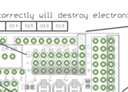
Next you will need to wire your TX and optionally the RX pin on your Arduino to the Ramps board. I do this on a Rambo board, but looking at the pinout for the RAMPS board, you want to wire the TX pin on your Arduino board to the pin 19 on the RAMPS board. The RX pin of your board connects to the pin 18 on the RAMPS board. You only have to do the second connection if you plan on receiving data back from the RAMPS board. I power my second Arduino board from the power pins on my Rambo board. With the RAMPS boards, I’m not sure this is a good idea. The clone Mega boards are known to have weak/faulty voltage regulators. If you power your Arduino board separately, you will need to connect the ground of both boards together.
According to the pinout for the Ramps board, you can find pins 19 and 18 in the upper right of the diagram as shown here:
Also to get the two boards to communicate, you need to set your baud rate at 250000:
Serial.begin(250000); // Default Marlin baud rate
Edit:
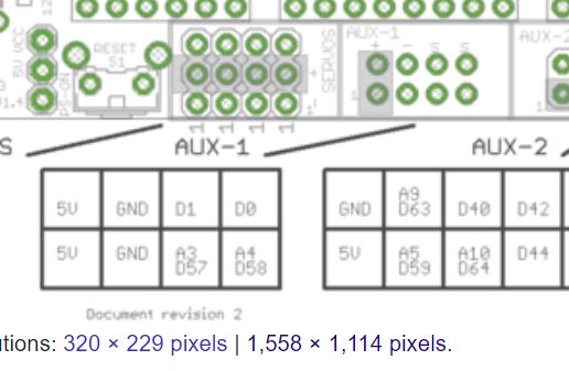
I run headless, so I don’t have a USB conflict and therefore did not need to change the firmware to communicate. If you want to do the same (even if only temporarily), you can use D0 (RX) and D1 (TX) instead of D19 (RX) and D18 (TX). These pins are found at the middle bottom of the pinout diagram:
1 Like
Yes, It works. compiled with #define SERIAL_PORT_2 1 that match with serial1 on the arduino mega. So pin 19.
Thank you very much. I will send a video when it all installed.
Did you get it finished? Share the video please 
So I realize this is old, but does the nano use the only serial port on the 2560, or are there 2?
You can use a secondary serial port, but you must enable it in the firmware. This involves modifying/enabling this line in the configuration.h file and reflashing the board:
/**
 * Select a secondary serial port on the board to use for communication with the host.
 * :[-1, 0, 1, 2, 3, 4, 5, 6, 7]
 */
#define SERIAL_PORT_2 -1
You did not expecitly ask about the the Rambo board, but on that board:
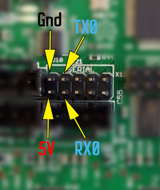
TX1 and RX1 are the next pins to the right.
Sorry, I have ramps 1.4 and 2560. Thank you for your information!
A quick look at the Mega board pinout and the Ramps 1.4 pinout gives:
Serial port pins
Port  RX   TX
0     D0   D1
1     D19  D18
2     D17  D16
3     D15  D14
Of these pins, the only pair on the Ramps 1.4 pinout diagram is Serial 2 (D17, D16). They are on Aux 4. If you have a display, these pins will be covered and probably used. You would then have to dig deeper to see if any of the other serial pins are available.
Edit:
I dug a little deeper and found the other serial pins mapped as follows:
D18 - Endstop Z-Min
D19 - Endstop Z-Max
D14 - Endstop Z-Min
D15 - Endstop Z-Max
D12 - Fan 2
D13 - MOSFET
D13 controls a MOSFET, but I’m not sure what that MOSFET is designed to control…maybe another fan. If you need serial pins, and you are not using the features listed, then I suggest intercepting the pin before it connects to the Ramps board.