ive got my mpcnc primo setup and running ryans rambo 1.4 and dual endstop setup. problem is i have it all setup and can get it to move using both the lcd controller and a mac running repetier. but when i try to home it either moves the x and/or y away from 0,0 about 10cm and then moves z axis down 10cm then up infinitely (i have to emergency stop). The rambo board is from ryan so it should have necessary firmware I just cant seem to get the machine to do anything except jog x y and z, but cant home X Y even using the V1 settings on the rambo board to home XY. Dont know where else to look. every search brings up 5 year old forums
In Repetier, issue an M119 command and see what the results are.
If the switches read as “triggered” then you probably wired them as normally open, instead of normally closed. On the 3 pin switches like Ryan sells, the common and normally open terminals are on the outer edges, don’t connect anything to the middle.
When it is trying to home Z, that should be the touch plate that stops it. If it is going upwards, you may have the Z motor plugged in backwards. Increasing Z should raise the tool off of the table, decreasing it should lower the router towards the spoil board. If you have a touch plate, it should stop Z movement when the “S” pin on Z_MIN connects to ground. (Usually you attach the tool tip to ground using an alligator clip, and have the touch plate connected to the “S” pin.)
I’ve tried running m119 and nothing seems to happen. I have the outer pins on the endstops wired. Maybe I have the s and ground reversed on the main board? And z being backwards is a possibility. I don’t have a touch plate.
There is no polarity in the endstop switches, so reversing “-” and “s” will have no effect.
It is meaningless to home Z without a touch plate.
The M119 needs to be executed from RepetierHost, and the result will show in the RepetierHost window.
The “10cm” moves are puzzling. The retest movements coded in the V1 maintained firmware is 5mm.
The Z movements are also puzzling. Note that you can flip any connection between the stepper and the control board to reverse the direction as Dan suggests.
Dan’s ideas are solid recommendations and are common issues, but I cannot help but think there is more going on here than simple wiring issues. Are you sure you have the right firmware installed?
10 cm? I read that as 10mm
The homing sequence (G28)should do this:
- Lift Z an arbitrary small distance (To be sure that it’s not dragging)
- Move X towards home until stops trigger
- Move Y towards home until stops trigger
- Move away from the endstops an arbitrary distance (5mm)
- Move back to the end stops at about half speed.
- Lower Z an arbitrary distance. If you homed with
G28 X Ythen it’s done now. - Lower Z until the touchplate is triggered.
Once you get the X and Y sorted out, I would strongly suggest you get a touchplate.
M119 sent from Repetier host should bring up a list of endstops (including the Z touchplate) and their status. You want them to be “open” when the gantry is not homed, and “triggered” when the switches are pushed. You can push them with a finger to test. (You’ll need to send the command again at the time, the responses don’t update on screen.) Given that information, it should be possible to start debugging the problem.
Also, if you have the LCD, it should tell you which revision of the firmware you’re starting with. 510D is the current dual endtop firmware.
So i just confirmed it is the latest firmware (510D 2.0.7.2). When i use the LCD to control the cnc, I am able to move all axis and all axis move properly. If I try to home X in the “motion” pane, Z axis rises but then X moves 5mm away from the endstops. Same happens for Y. If I try the home XY command in the “V1 custom” pane, the same happens, Z rises a bit then x moves 5mm away from endstops then y moves 5mm away from endstops. both axis are centered in the middle of the build area when I try this. I will be adding a touch plate eventually. I am hooking up my computer next to test m119 code and see if the endstops are working properly. Note though that I am using an older mac now and I had to switch baud rate to 256000 to connect. Also sorry I miswrote cm instead of mm before and was just estimating 10mm movements but today confirmed 5mm movements.
Ok so now M119 seems to be giving me results:
Without any endstops engaged,
< 12:33:25 PM: x_min: TRIGGERED
< 12:33:25 PM: x2_min: TRIGGERED
< 12:33:25 PM: y_min: TRIGGERED
< 12:33:25 PM: y2_min: TRIGGERED
< 12:33:25 PM: z_min: open
Now if I press and hold one of the endstops and then run M119 again, nothing changes. all say triggered still.
So am I correct in assuming that the machine, even when the core is centered in the build area when I go to home X Y, the machine thinks the endstops are already engaged, thus moving each axis 5mm away from home direction.
The endstops appear to be wired correctly, but reporting “triggered” means that there’s something wrong.
The endstop ports on the board have 3 pins, They are (S) (-) (+)
If you connect (+) and (-) with the switch, you could damage the board! Don’t do that!
If you connect (+) and (S) with the switch, you will get “triggered” all the time.
(-) and (S) are the correct pins to use.
Be careful! the pin order is reversed in the second row,

You want to be sure that you are connecting (S) and (-) pins, and not connecting the (+) pins to anything.
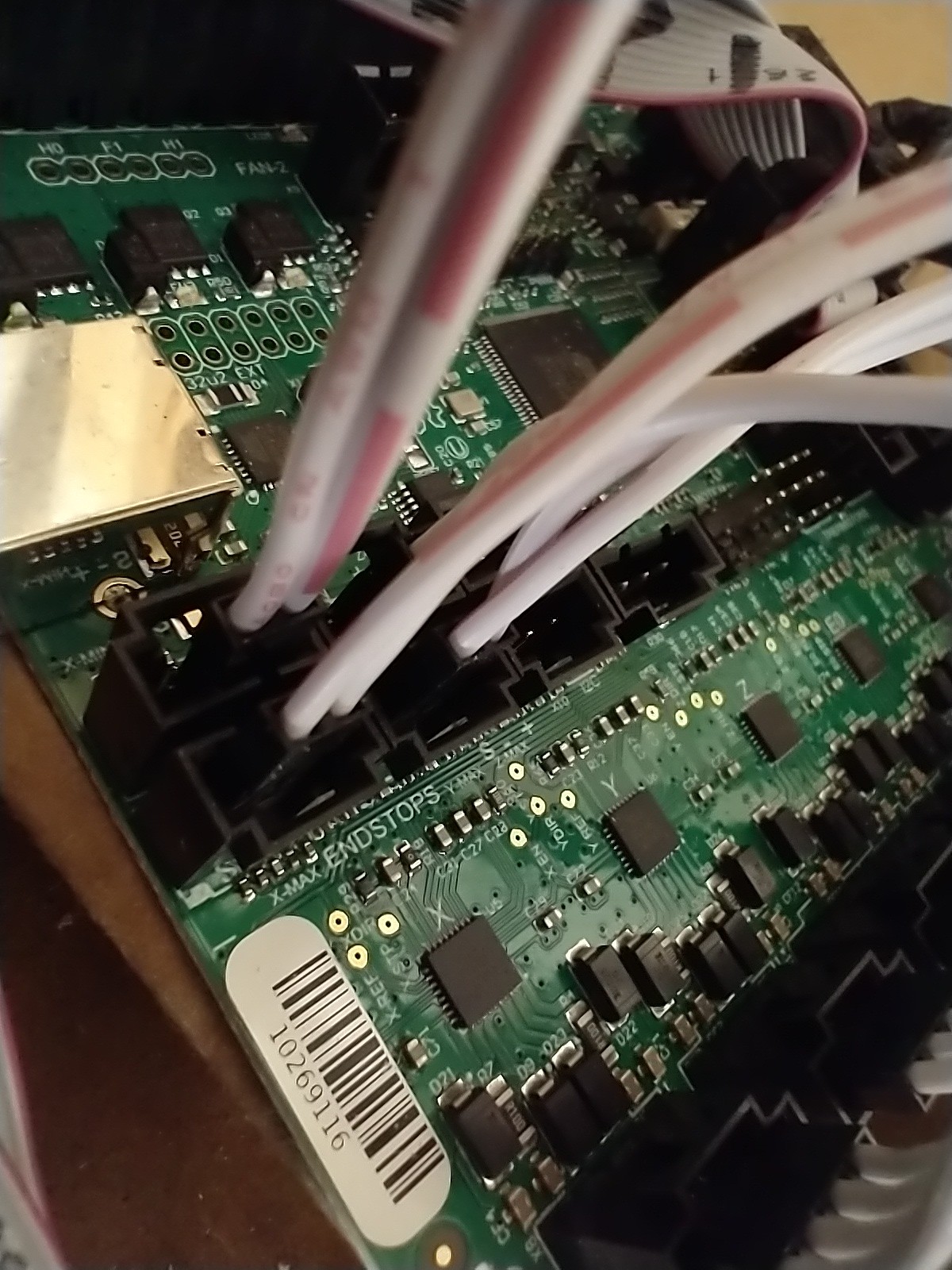
This is how they’re wired to the board. I followed the image in your reply when wiring and believe they are correct. Using the wiring kit from Ryan the wires are connected with a header making it impossible to connect + and s without separating the wires (which I didn’t do)
Hard to tell from the pic but just went and confirmed they are correct and on s and - in each respective row
Also it’s odd because if I engage a switch and run m119 then it should read as open if they are triggered when not engaged. But they all read triggered regardless of being pressed or not
Well, the “nuts and bolts” of how those stops work is this:
If the CPU reads +5V (Actually, I think > 3V) on the “S” line, it reads as “high” and if it reads 0V ( < 1.5V) it reads as “low” "Triggered = high.
There are “pullup resistors” on the actual board that buy resistors of a known value (I believe 470 Ohm) in between the + and S pins. This means that if there is nothing connected to the pins, they will read as high, and therefore triggered. This works as a safety for the endstops, because if the wires become disconnected, the stops read as triggered, which will prevent the carriage from crashing into the end of travel. When the switch is left alone, it shorts the (S) and (-) together with 0 ohms (OR really close to 0) which will overpower the 470 ohm resistor, and bring the value down close enough to 0V to read as low (open).
With your switches wired that way, reading “triggered” is the same as saying “diconnected.”
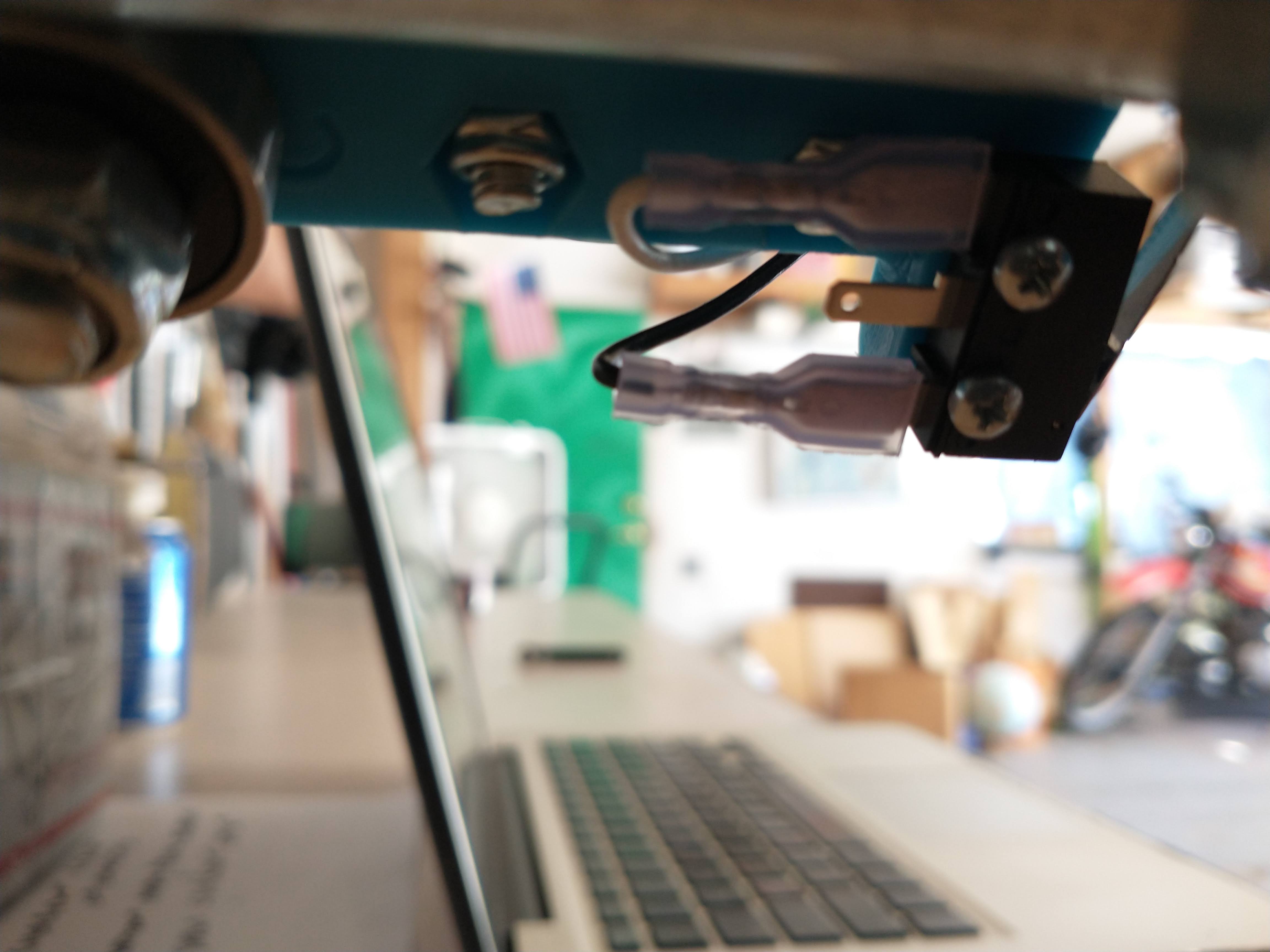
I see that the wires at the switches themselves are black and white, but both white at the board. That means that there’s a junction somewhere. You’ll want to check that.
Just in case:
You can check normal operation of the board/firmware by taking a jumper and putting it directly on the board between the (S) and (-) pins. M119 should then return values of “open” for those endstops.
You’re correct there’s a junction. I’ll double check all my wiring tonight with a multimeter. Thanks for all the in depth answers. I’ll report back after tinkering.
So I busted out the multi meter and it seems the endstop wiring provided by Ryan doesn’t have continuity. They are the wires provided for the endstops with female paddles that go on the endstops and the other ends junction with extensions. Guess I’ll have to make my own wires and connections for endstops. Hopefully is the culprit. A bit annoying too.
Seems to be the paddle connector crimping is no good.
Ughhhh, I will let Ultimachine know. That has happened before.
Thanks for the heads up, and sorry about the hassle.
1 Like
Not a big deal. Just cut off the connectors and soldered to switches. All working good now. Next step learning how to run this bad boy  really appreciate how quick and knowledgeable the community is here!
1 Like