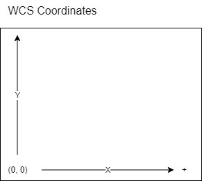
My problem is very much this issue of X and Y axes values going negative. This explained that in the Fusion CAM setup, you place the origin (WCS?) in the lower left bottom of your model.
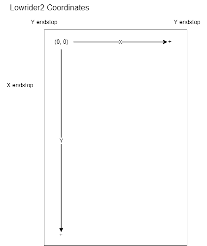
My Lowrider2 has the double endstops installed. The custom Rambo 1.4a from Ryan has the DualLR firmware. Attached is a Raspberry Pi 4b with the latest Repetier-Server software and a 7" touch screen. The movement is setup like this:
A G28 command correctly causes the system to move to the origin point (upper left) with the Z-axis moving to Max for squaring. That works. There may be an issue with the G38.2 touch plate. From a workflow standpoint, I’d like to home the system, zero the Z-axis with the touch plate to the stock, upload the post processed Fusion 360 CAM gcode to the Repetier-Server, and tell it to “Print”. Will my endstop setup work?
My Javascript is pretty good, but the cps file is a new animal to me. Even if the post processing could be enhanced to move the X Y position to the lower left of the model and reset the origin (G92) there, would that even work? Since the steppers think increasing Y is down, not up.
Note: There are supposed to be 2 embedded diagrams above.
You have made a “left handed” coordinate system. That will always be mirrored in some axis. You need to reverse the direction of Y and move the endstops to the other end.
I wrote a primer on coordinates here. Not sure if that will help or not:
No. It definitely helps. I am just powerfully unhappy. I thought I was almost done and now I need to lift up the whole carriage, possibly knocking it out of alignment and move the Y endstops… again (3rd time). Everything was finally moving so quietly. Plus I have to redesign where the control box and other components were going to sit, and the vacuum table. It violates my vision. My control box is not on the carriage. I have drag chains. But thank you. At least I hadn’t cut the waste board and vacuum layer.
There is a way to fix this in the software and wiring. It won’t be easy.
But if you swapped the X and Y, so the positive X was going down, and the positive Y was going to the right (in your picture), then you would be back to a right handed coordinate system. You would just imagine yourself on the left side of the table when you were working on CAM.
The trouble is, you’d need to edit the firmware settings, recompile, and reflash your board. Then you would have to move some wires around to swap out X and Y and the endstops. But that would all be at the board, so it shouldn’t require any new wires.
I bit the bullet and moved the endstops and essentially flipped the wires on the right and left Y steppers. Unfortunately it was as painful as I anticipated: the two new couplers broke (one with a stripped hex bolt so I had to cut it off with a Dremel, one of the bands popped off and the Z-axis had to be squared about 10 times, and initially the Y-axis movement was noisy. But it is working fine at 9pm at night. I ran into another problem, which I will post separately. Sometimes the truth is harsh, but thank you for letting me know the right thing to do.
I use GRBL so I am not familiar with how Marlin deals with work coordinate systems. In GRBL, I would jog the core to the lower left corner after it was homed and define a work coordinate system (G54). Does Marlin only have a machine coordinate system?
Your solution won’t work in grbl either, I’m afraid. The coordinates would still be mirrored.
If there were no endstops, or dual axis, then it would be easy in Marlin. But having dual endstops and auto squaring is where the settings are that need to be changed.
G54 isn’t enabled by default, but you can easily set the machine coordinates with G92.
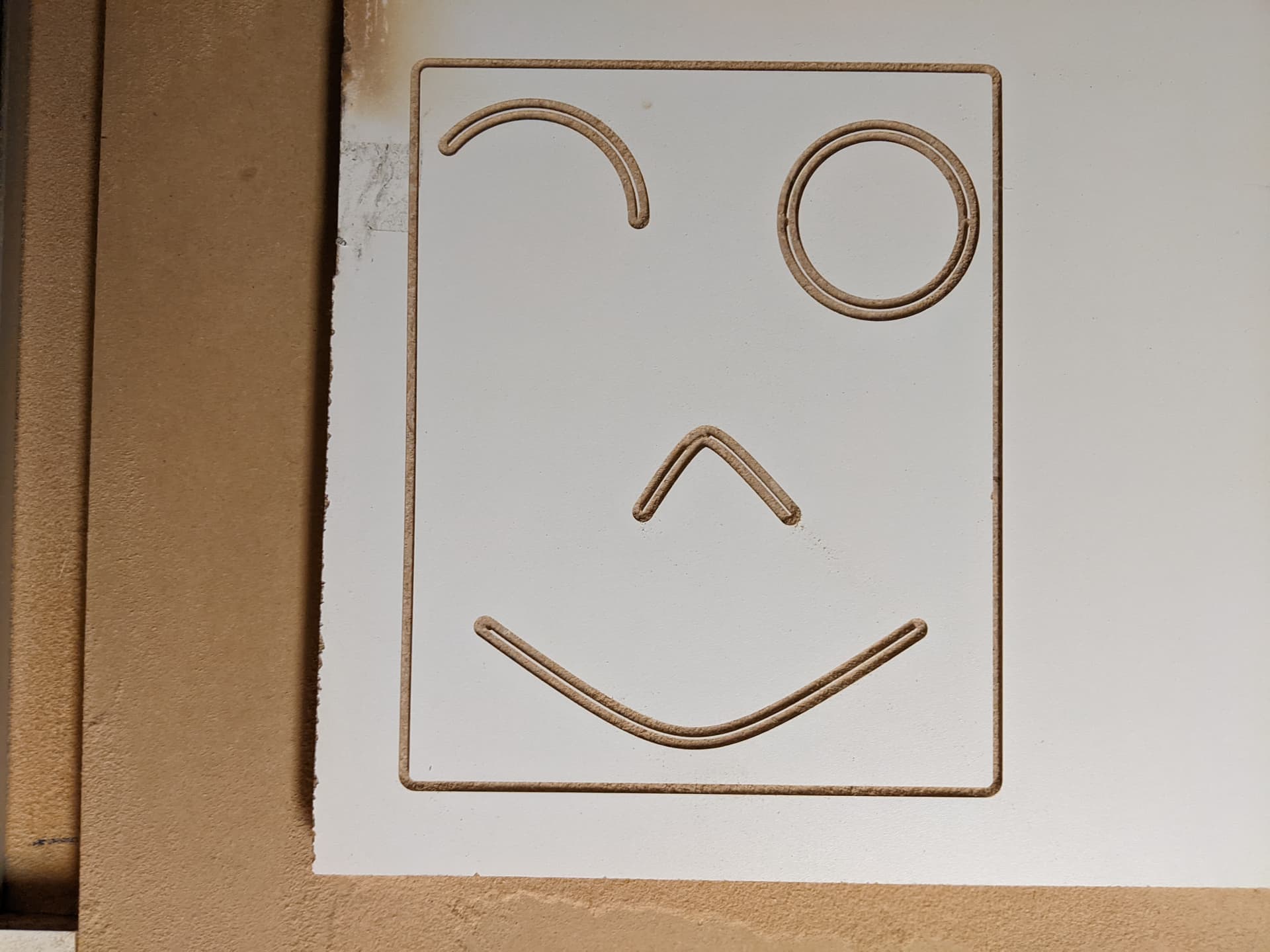
BTW, I was able to cut my test smiley face gcode. It shows the machine is square and accurate in its measurements. Thank you for all your help. Lots more work before the Lowrider2 is complete.