False alarm - the reset/single cable fell out!
1 Like

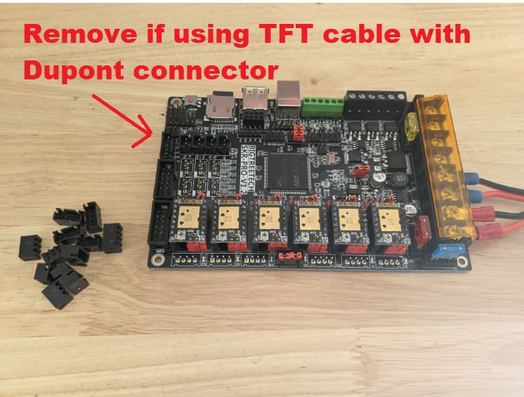
@jjwharris, did you remove the JST plastic shield from the SKR Pro TFT port, before connecting the black cable between SKR and TFT boards? V1E kit’s wire with Dupont connectors make more reliable connections if the SKR’s plastic JST shields are removed first for the ports we’re using. I did NOT remove shields for the grey wires connecting SKR to TFT.
Mentioning because SKR assembly instructions Docs → Control → SKR Pro → Molex and JST connectors talks about removing the JST shields, even has a pic. However, the doc doesn’t explicitly mention, or show that the TFT’s JST shield should be removed as well to help make for a more solid connection.
Hope someone from LR3 Beta crew can confirm/correct my understanding.
2 Likes
The shield didn’t really feel like it wanted to come off, but I got it off and am running with no problems!
Thanks for the quick reply.
I also swapped my PSU out for a 24v 6a vs the 2.5A 24v I had on hand
3 Likes
You’re welcome. Hope it helped. I struggled to remove mine as well at 2am this morning, was questioning my judgement through out. But the Dupont connections felt solid afterwards. Used Jeweler Precision Pliers stolen from my wife, my regular electrician needle nose pliers were way too big and likely to damage the board components.
3 Likes
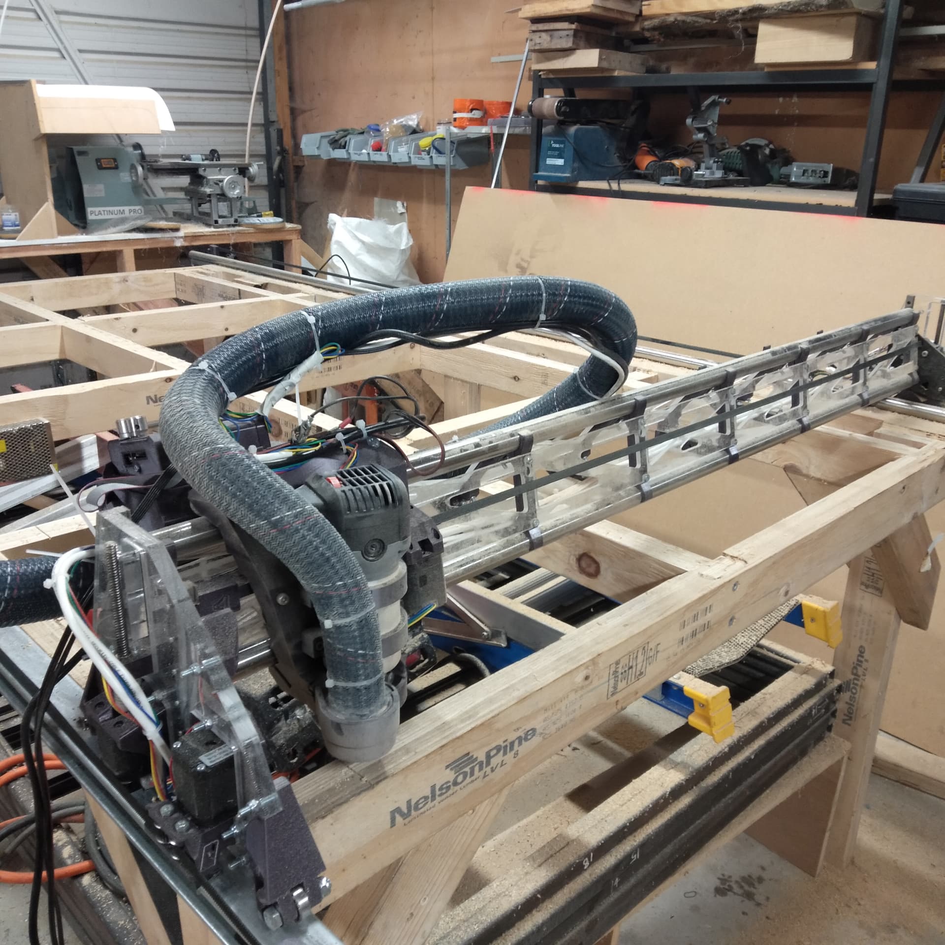
I’m nearly at the finish line…
Everything seems a lot more rigid, and I seem to be getting faster speeds/less stressful/worrying cuts than I did years ago with the LR1/2…
Aside from cutting the strut plates, I’ve begun surfacing the trusses on my table, it’s a bit of a drag as they seem to vary by 0-6mm, but hopefully this sorts it out. I’m running a toolpath at 2000mm/m, 3mm DOC, with a 25mm surfacing bit.
The toolpaths are just 651220 and 652440 6mm pockets.
It’s a real delight to have the endstops, it makes everything much easier, I think I may need to readjust the offsets once the trusses are surfaced, but my initial squaring ended up with 0.5-1mm on the diagonal
10 Likes
Wow looks sturdy, nice build!
1 Like
Man that looks cool!
1 Like
That very idea is something I had started pondering on within the past few days, as I started thinking about a plasma cutting table.
I’ve been playing with the speeds and feeds - I haven’t saved any of these settings to the EEPROM because I don’t really fully understand what I’m doing…
I’ll have a read up, but I imagine I should be able to kick the travel speed up, while the cutting speed will be pretty severely reduced since I’m cutting arcs/circles.
A full sheet of record blanks is about 160+ Up/Down Z Movements (Outside diameter, plus centre hole), I figure the Z clearance is probably going to be the big one.
I’ve surfaced the struts of the tables, I’ve put a straight edge over the table, but I’m still not entirely sure how flat the surface is. I could probe the entire surface and map the table, but that could also be a bit of a nightmare.
1 Like
Seen the swing a stick a see what you hit method?
Edit: Never mind, ignore me, you’re working to way higher tolerances/quality than me. For anyone interested, was referring to this basic tram method…

2 Likes
I think I will attempt to tram the router, I was surfacing with a 23mm bit today and I was getting quite bad ridges on the surface.
I’m hoping that surfacing the frame of the table has taken the whole sheet to within 1-2mm, but it does seem that the router isn’t completely adjacent(?) To the plane of the table.
Once everything is trammed, I could probably do another quick surface of the frame if needed.
Carved this today, a prototype, and my cam needs a lot of work. Machining time was probably only 20-30 minutes, and that was with me being terrified.
I forgot about finishing passes and proper work holding which was the real issue!
8 Likes
Love the look of the clear acrylic!
1 Like
I think this tramming approach has potential, however wouldn’t it be thrown off drastically if the holes that get drilled (that get the bits inserted in them) were not perfectly straight? And drilling perfectly straight manually is pretty easy to mess up.
EDIT:
On second thought maybe any inconsistency will simply be mirrored equivalently in all directions. I’m a bit sleepy so I’m not sure I’m considering it fully.
1 Like
You can use a bent wire hanger, the curve /angle/bend doesn’t matter. The sweep stays the same.
3 Likes
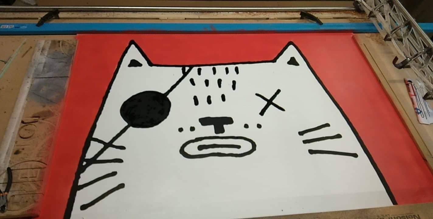
Plotted this out today - it’s 1000*1300mm, I used a poska bullet tip pen which was cable tied to the dust collector to draw the edges.
The image was handrawn and vectorised, so the pen followed the inside of the digitized pen lines with the part/hole setting in ESTLcam - trying to retain the hand sketched lines.
This left gaps on the inside of the digitised pen line, which were filled with a large chisel poska pen. The red was straypainted before the plotting began (but after the trial run with a whiteboard marker so I knew where the edges were!)
I mistakenly set the clearance plane to 2mm, but the pen didn’t touch the table anywhere it shouldn’t have, so I think the surfacing worked. There could be a bit of an issue with the welded Y rail being slightly warped, but the surfacing may have cleared that up too…
My 1.2mm sheets of polycarbonate arrive at the beginning of April, so that will be the real test!
This is the drawing in location, in the window of our dumb little record store in Christchurch, New Zealand!

15 Likes
Whoaaaa that window really puts a new perspective in it. How big is it? That is great!
2 Likes
only 1300*1000mm, I’ve got to plot out the second window too.
I’ve got the touch plate working - took a bit of figuring out but got there in the end.
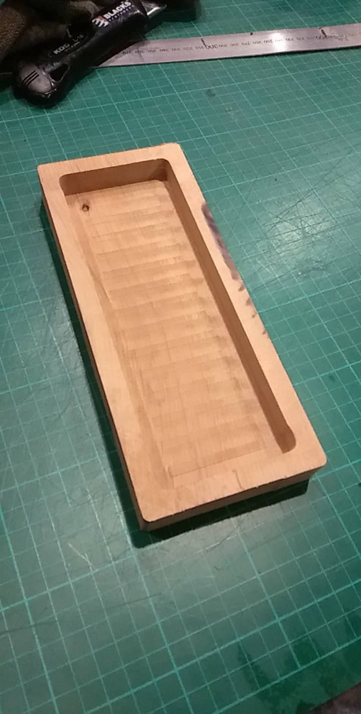
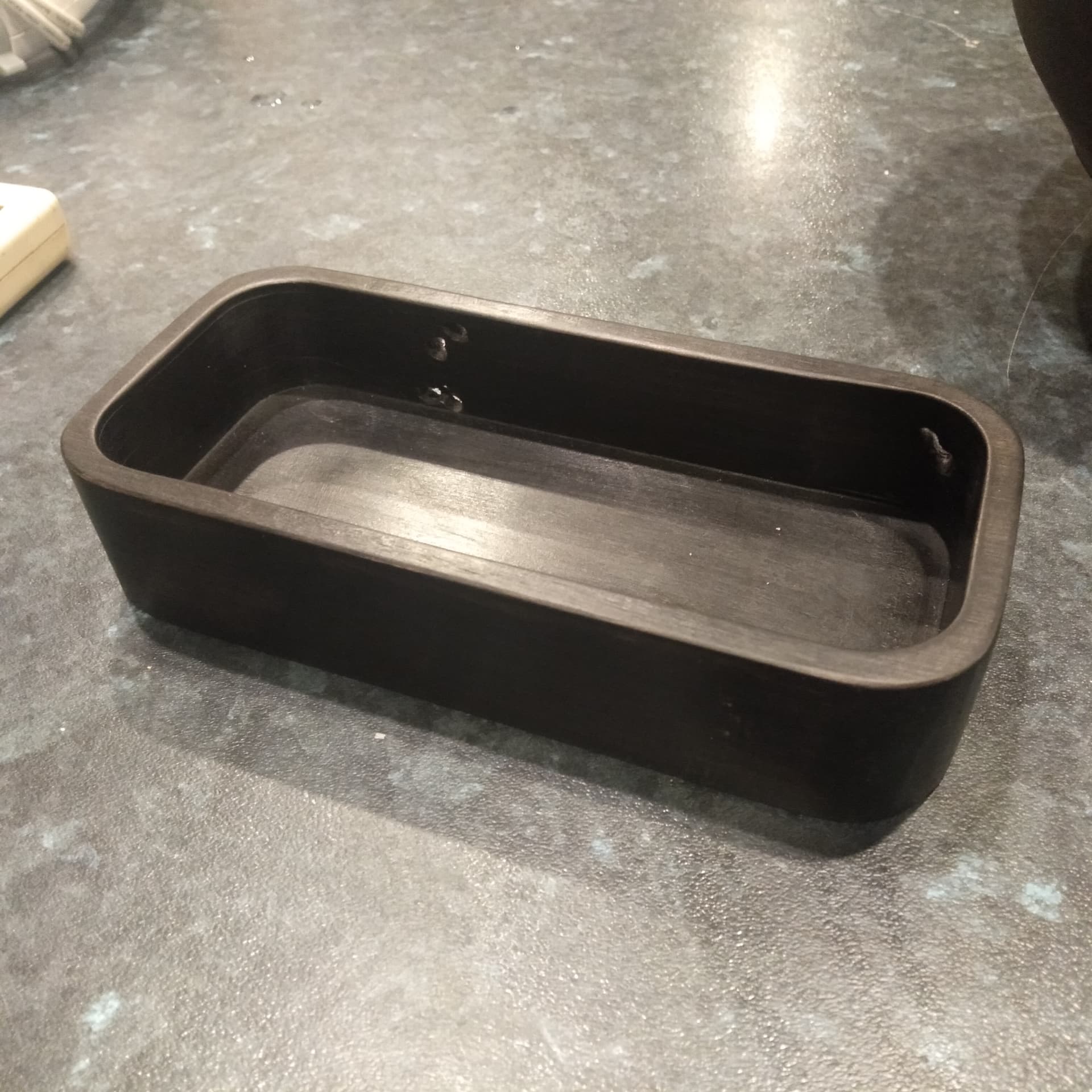
I’ve been making these wooden carved trays…it’s a bit of a baptism by fire, but machine time is around 15 minutes with tool changes.
The screws fell out of my linear rail blocks, I put them back in and tightened them up fully this time, there doesnt seem to be issues with the gantry’s lifting, I have noticed I sometimes get wood chips above the Z nut part that connects to the side plates, this means sometimes the Z won’t lift high enough to trigger the limit switches.
The real show stopper is the Z axis motors - I used the ones I purchased from the V1 Shop on a job before I built the LR3, so have been temporarily using some steppers that I had lying around - they’re from aliexpress and I think they may be a bit dicky.
On the part above, the z axis dropped on one side before I could do the final finishing pass on the inside, so I had to pull the power before anything went really bad…you can see the scorch marks for the collet.
Even still, this machine is so much nicer to use than the LR1+LR2
4 Likes
Using the dust shoe? I might need to revamp it to add a flexible skirt. I tested it with just a tape skirt and it does help a little bit.
I think most any 40oz/in plus steppers should work. Make sure you have free leadscrew movement with no binding. Make sure your Z rapids and movements are within reason. They should be at least 4x slower than your XY. You should be able to move your Z axis at 15mm/s no problem with any stepper. Larger ones are required for faster speeds.