For what you’re trying to do in this example, I’d recommend using Inkscape with the Jtech plugin. It’s much more efficient as it moves the laser along paths versus doing a raster scan.
Now that I have the basic concept working, I thought I’d check out what the Marlin team is working on - since if there stuff is nearly working it didn’t make sense to clean up my project. I checked out this pull request (big update just 6 days ago)
LASER improvements pull request
And that took me to the development fork…
I then did a merge of the MPCNC bugfix-2.0.x changes (which takes some work as Marlin has changed quite a few things) in Configuration.h, Configuration_adv.h and pins_RAMPS.h. Even then, it would not compile. Looks like they changed the name of a function (in status_screen_DOGM.cpp it references undefined ui8tostr3, that needs to changed to ui8tostr3rj). I also got linker errors, at least on Windows w/PlatformIO, that required I move the typedef for settings_laser_t out of the parent typedef (planner_settings_t) and into global scope and then it links and runs.
I then set up my oscilloscope to watch the laser PWM pin (which is D6) and the X stepper pin, and tried the M3 commands. To test, I set up a series of M3 commands to turn the laser ON/OFF, and move X and Y steppers to see how the signal works:
G92 X0 Y0 E0
M3 S0
G4 P1000
M3 S100
G1 X30 Y30 F2000
M3 S0
G1 X30 Y0
M3 S100
G1 X0 Y30
M3 S0
G1 X0 Y0
When I look at the scope, the laser pin is tightly aligned to the motion queue of the steppers, so that is great news.
However - the signal does not vary based on acceleration. It does align timing, but it does not change the pulse based on the overall speed of the gantry - it is a fixed burn signal. If no movement is in the queue and you use M3, the laser just turns on and sits there at power, further showing it isn’t monitoring movement speed.
UPDATE: This is wrong. If you use the new S parameter on G1 (G1 X10 Y10 S50, for example) the laser PWM changes with acceleration.
On a side note, either there is a bug or I have something misconfigured, because the pulse width never gets very wide, even at the full power setting. It varies in width between 0 and 4% duty cycle, but never above that. I’ve tried both percentage based (0-100) and PWM based (0-255) settings, with no change in pulse width.
Seeing as I’ve not yet powered up my laser, I’m wondering how much of the “laser problem” this solves? Other than Marlin soon having this “out of the box” (avoiding our hacks to get lasers working), is this any better than what we are already have? Is my approach for tracking extruder power and getting an accelerated power PWM worth finishing, or am I chasing a meaningless project?
UPDATE: So it feels like the external hardware solution is not worth completing. If anyone feels otherwise, please share your thoughts - else I’ll be dropping this project (was fun though for a couple days, and it really does work!)
There is a configurable max for S. IIRC, it defaults to something like 24000.
I think your approach of linking the extruder dimension is going to be the smart way of maintaining the correct power through accelerations. I haven’t looked into what the other approaches are, but if they are not using the E dimension then they will have to reimplement a ton of stuff to get correct behavior when acceleration kicks in, or set acceleration super high and sweep it under the rug.
I apologize, I haven’t been paying attention to what you’ve been doing in Marlin but if I were implementing this I think a reasonable path from the start would be:
- External hack:
a. Marlin is ignorant of laser and external CAM or postprocessing converts laser intensity into extrusion movements in the gcode
b. External Arduino or something catches the step pin intended for the extruder driver and inserts a fixed-length pulse based
c. Check that it works - Internalize external Arduino to Marlin, still use extruder gcode but internally intercept the extruder step pulses and insert timer-based fixed-duration pulses on a laser pin. I would expect this is tricky.
- Synthesize the extruder dimension based on movement length and the most recent M3 command.
The new laser support has scaling in use for S, it is default 0-255 and optionally percent (0-100, by setting CUTTER_POWER_PERCENT) or RPM (when using spindles, by setting CUTTER_POWER_RPM). But I’ve tried the different settings with no change in PWM, and I also tried changing SPEED_POWER_MAX (for laser) from 100 to 1000 but that didn’t help either. There is also a slope (SPEED_POWER_SLOPE) and intercept (SPEED_POWER_INTERCEPT) but I’ve not played with them yet (it defaults to 100/255 or .3922, to scale 0-100 across the 0-255 PWM range)
I was suggesting M3 S10000
Hold on … turns out Marlin does ramp PWM. It isn’t done with M3/M5, it is done with a new S parameter on G1. For example, G1 X10 Y10 S75 would run the laser, proportional to acceleration, at 75% power. I put it up on the scope and it works! But still has the PWM pulse width issue above, but that likely is my configuration or a tiny bug.
Doesn’t work (using M3 S10000 to fix the PWM problem with the Marlin laser fork). It seems to actually wrap, meaning slows down or odd speeds at high numbers. If I set to percentage, it only likes 0-100 (doesn’t like 150 for example). Likewise when in PWM (0-255).
Doing bench tests only (no laser yet), I’ve been able to get great looking accelerated/decelerated PWM using Marlin bugfix-2.0.x with the laser fixes fork … but it took some debugging.
The steps so far are:
- Get the code from Laser Fork (or perhaps better, get Marlin bugfix-2.0.x and merge in changes in merge request ([Marlin Laser Fixes]https://github.com/MarlinFirmware/Marlin/pull/15335), though I’ve not tried that yet)
- Merge the needed changes from MPCNC Marlin files into the new Marlin (this takes some work, you will really need a 2- or 3-way merge tool). The files are Configuration.h, Configuration_adv.h, and pins_RAMPS.h (or whatever your board is, mine is RAMPS)
- Move the typedef for settings_laser_t in planner.h outside of the planner_settings_t typedef (move it just above it)
- In status_screen_DOGM.cpp, you will get a compile error on i16tostr3. Change it to i16str3rj.
- In Configuration_adv.h, uncomment LASER_FEATURE, LASER_POWER_INLINE_TRAPOZOID_CONT, and LASER_POWER_INLINE_TRAPOZOID_CONT_PER (and set it to 4, which seems to work well)
There are two killer bugs, both I have fixes/workarounds for:
- On RAMPS, and maybe other platforms, the PWM rate is being set wrong because they are mixing called using fast_pwm and regular AnalogWrite. The fix is to edit spindle_laser.cpp and change SpindleLaser::set_ocr where is called AnalogWrite. Simply change AnalogWrite to set_pwm_duty.
- When decelerating, and a few other conditions, the laser does not turn off when it should. The code caches the last value incorrectly, and decides that it is off (or really any other level) when it is not. I have a hack fix that removes the caching, and it seems to work fine with no meaningful side effects (that I can see). In spindle_laser.cpp, in the method SpindleLaser::apply_power, comment out the 2nd line (that contains “if (inpow == last_power_applied) return;”)
I’ll also shared this with the developers on GitHub so hopefully we will see a real fix soon.
2 Likes
I suspect they really appreciate that. Marlin is pretty actively managed and open to PRs. If you want to go the extra mile, add in a test configuration enabling these features. Then other PRs will need to pass your test configuration before merging.
Anyone who wants to try out the new laser code, I have made a repository at https://github.com/cmidgley/Marlin. This version is configured for RAMPS, dual-endstop, plus a few custom changes in Configuration/Configuration_adv.h. All custom changes (those that would not be considered normal for an MPCNC configuration, or are hacks/patches I made to get it to work) are labelled with a comment starting with “// CWM: (comment)” if you want to preview.
Be warned - I’ve only run this on a bench RAMPS machine and not connected to an actual MPCNC. I’ll be doing that in the coming days, so there may well be serious issues!
2 Likes
Update on the Marlin codebase - the developer made the changes I recommended, and the code appears to be working great (again, on my oscilloscope, no real laser burns yet). I’ve updated my fork with those changes (including latest changes from Marlin/bugfix-2.0.x). Do be aware that I’ve also enabled AUTO_BED_LEVELING_BILINEAR as I am working on PCB carving as well and wanted to experiment with mesh leveling the PCB for more accurate V-cuts. As before, all custom changes I made, that would in theory be different than what I believe Ryan would have made, are marked with "// CWM: " comments, and that I’ve only updated for RAMPS/dual-endstop/32-step.
I just ordered an Archim 1.0a from Ryan, so when I get that I’ll update the fork for that configuration. I’m doing this because the MEGA is considered too slow to do LASER_POWER_INLINE_TRAPEZOID, which I would like to have (RAMBO should be just fine as well, I just went with Archim as I am doing some high precision 0.05mm PCB work as well, so wanted 32 steps).
3 Likes
Yesterday they merged the laser code into Marlin’s bugfix-2.0.x branch. I’ve not yet updated my fork, but will do so soon using just that branch. I did test the code on my fork (which is basically what is now in bugfix-2.0.x) and it works great with a spindle on aluminum and wood, so it feels like the settings are right. Will be doing laser soon.
Hey @cmidgley ,
I read through the thread a bit (but not all of it of course) and have the same problems as shown from the beginning posts. I have a dual end stop configuration and my laser module is up and running using TTL on D44. I can flash the above fork of Marlin and if you have some G code you want another crash dummy to test, post it up and I can run it asap.
I uploaded the bugfix code from @cmidgley 's repository and made a few changes based on my setup. Lser TTL is fed from D6 now with D4 being some sort of enabling pin which I can’t understand how it works.
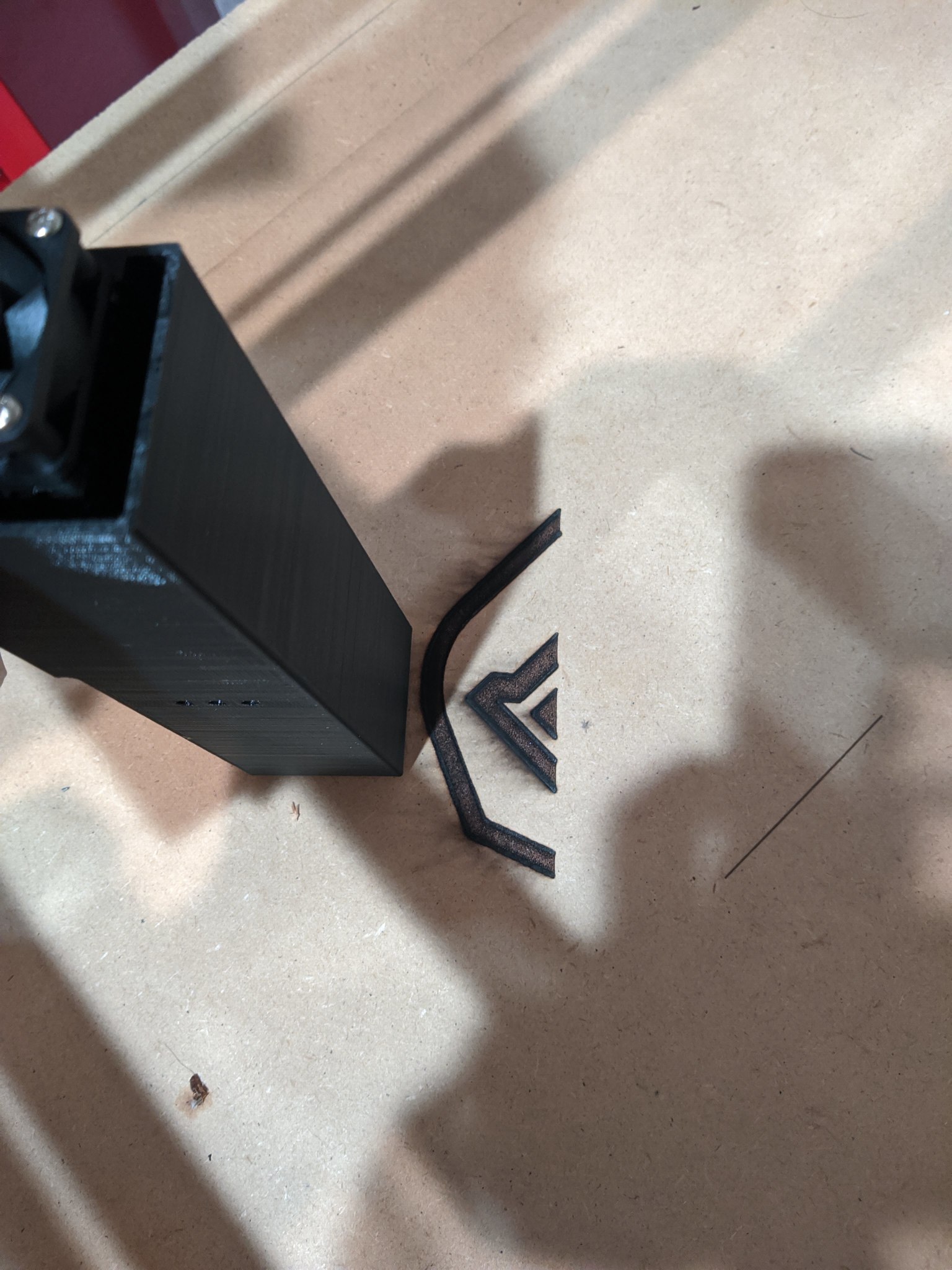
It’s performing much better but I think it could use a little tuning. It seems to slow way down on edges and I think it is over lasing these areas. I also added a laser shroud which is causing the smoke issues.
To get it to work, I had to replace all my M106 commands with M3 commands.
Sharpness has increased magnificently! I’m going to keep playing with the jerk/acceleration! and try other images.
Old Marlin at a feed rate of 800 mm / min

New Marlin & Shroud at a feed rate up to 1600 mm / min (I changed feed rate throughout test, see if you can tell where)
Source Image

Thanks for trying it! Good to hear it is working.
I was worried about this. Some thoughts:
- If you are using RAMPS (or something slow like that) you might want to play around with the LASER_POWER_INLINE_TRAPEZOID features as they have mentioned that RAMPs gets bogged down with these and therefore may be less responsive (and causing edge burns?)
- On the other hand, if you have faster processor, try changing LASER_POWER_INLINE_TRAPEZOID_CONT_PER. It defines how rapidly power will adjust, and I have it set to 4 but perhaps it should be faster (such as 1)?
- The default intercept/slope is linear from 0 to 255 (across a 0-100% power). You might want to adjust that by changing SPEED_POWER_SLOPE and SPEED_POWER_INTERCEPT (in the laser section) so that the laser has lower power at slower acceleration speeds.
You can use D4, for example, to control a relay power outlet. This way you can power off the entire laser system, rather than leaving it powered up and increasing risk of accidental laser engagement. I use IOT Relay from Amazon.
If you do any more tests, please post the results! I’ve finally got everything for my laser, but I’m distracted on another project right now. Hopefully I’ll get back to the laser soon.
1 Like
@cmidgley I have a switch that controls a relay that controls my laser, its generic like this https://www.amazon.com/dp/B0151F3A9Q/ Granted that leaves room for operator error but it’s worked so far. glasses on switch on; switch off glasses off.
I am using a basic RAMPS board with a standard MEGA and DRV8825 drivers. I’ll play with the LASER_POWER_INLINE_TRAPEZOID settings and report back.
Thank you for all your work!
1 Like
wow…there is a load of great work in this thread!..I am left though thinking that a MPCNC, a RAMB0 board and Marlin is a bit of overkill for a simple laser engraver. a lot of the problems that have been encountered in this thread were because you have started out with less than ideal hardware and software for this task.
A simple lightweight frame that can position the laser head is all that is needed, RAMBo has all mannor of extras that are simply not used and Marlin does not appear to me to have the laser mode that GRBL has, this not only allows the laser power to be ramped up and down according to head speed but also keeps the head moving during spindle speed changes…an absolute game changer when lasing.
for those who might be interested I documented a cantilevered laser engraver (actually used to cut out balsa pieces) on another forum a while ago…here
I have just done a quick engrave on 8mm ply… I couldn’t find the Garfield that David used but I used a similar one.

I have a youtube video of the long version of my cutter working Here
2 Likes
So this had me playing again…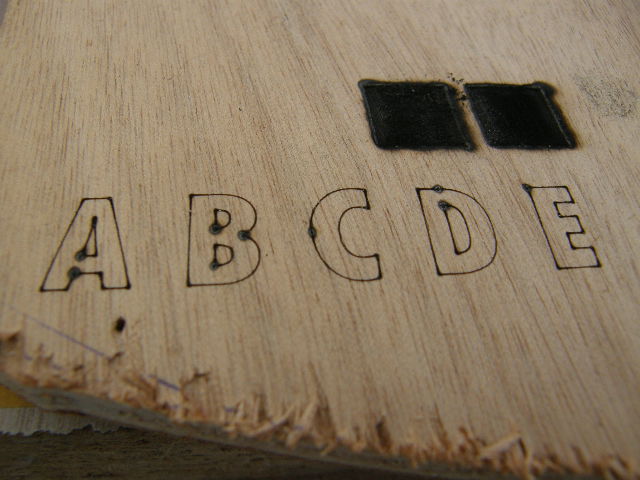
This is the result of having some Z component in the gcode, the laser is on awaiting the carriage to (not) move in the z axis…you don’t want any Z component in the gcode!
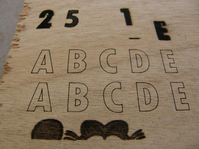
playing with the feed speed with vector graphics

Playing with the infill in a carve toolpath, also crosshatch v offset infill
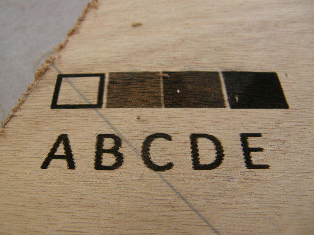
Raster graphics
PWM.zip (2.1 MB)
Quick video of the PWM working
1 Like
Hey, MIke! Thanks for your comments. I pretty much agree with everything you said but do feel compelled to mention that Ryan’s MPCNC platform was originally designed to carry a spindle… and that the addition of lasers, needle cutters, drag-knives, pens/markers, etc. only serve to show its versatility. If Ryan’s original intent was to simply design a laser engraver… yes, it’s overkill.
I like your cantilevered laser engraver design… I’d not seen it or the ModelFlying forum. I have, however, built a couple of Edward Chew’s TimSav foamboard cutter systems… which greatly resembles your machine (and, apparently, that ripped-off Chinese design ![]() ) and carries a needle cutter, originally developed to cut RC plane parts out of foamboard.
) and carries a needle cutter, originally developed to cut RC plane parts out of foamboard.
When we were doing all the testing during this thread, I had a “stock” MPCNC, running Marlin, that I had set up as a laser engraver… using the M106/M107 fan control gcodes. And, yes, we quickly uncovered the fact that Marlin wasn’t really designed with a laser in mind. While I was getting a reasonably good-looking raster engrave… others were not. Ultimately, we discovered that relatively “innocent” changes in the fan control section of later versions of the Marlin firmware seriously impacted its use for controlling lasers. A work-around was found and soon everyone started getting reasonably good Garfield engravings. But, yes… it is still “lacking”, especially with the stop and go action with power changes and not ramping the power as the laser speed adjusts to enter and exit a corner or boundary.
Fast forward to now… I’ve joined the Lightburn and GRBL crowd. Not disparaging Marlin’s use with MPCNC… but since much of what I do nowadays is lasering and pen-plotting, I’ve found GRBL’s “laser mode” to be far better suited to my need. Several threads in this forum (here, here, and here) show laser engravings far superior to what I was able to achieve with the Marlin-based testing we did in this thread.
And, now, inspired by @geodave’s Rolling Plotter build, I’m currently testing and adapting a version of it as a “rolling gantry” machine. It not all that dissimilar to your machine in that… it uses “tractors” where your machine’s feet are, uses the long axis almost verbatim, and essentially turns your cantilevered axis 90*, to become the Z-axis.

As mentioned, I’ve also joined the Lightburn camp and can’t begin to say enough good things about it, when it comes to laser engraving. One fellow in particular, @Bulldog on the Lightburn forum, has been doing incredible engravings on wood, ceramic tile, children’s scratch pads, etc… all with just a 2.5 watt laser. It’s been great fun applying his tricks and techniques to my own engravings.
Again, I like your work… and thanks for sharing! I look forward to seeing more from you… ![]()
– David
1 Like