Laser engraving - not really getting great results

I have one of these: https://www.amazon.com/gp/product/B00WAQGGZA

I needed a 9V PSU, leads, and it was tricky to build. I think there is a genuine somewhere, and I don’t think this is it, but it does work.

I also bought a USB silly scope that I have used with my Linux laptop, but not my pi (yet). I hope that ends up being a nice setup at my bench. But the kit I linked would be good for this stuff. I’m pretty sure it’s tolerant to 30V? But I could be misremembering.

There are some oscilliscope labelled things that look like multimeters. Be careful, because some of them don’t actually draw the waveform, they just draw either a sine wave, or a sawtooth, or whatever pattern they think matches best.

This is the USB scope I bought, which is pretty nice, and I have used it on my desk, with open source tools. I didn’t try the windows applications it comes with:

I have no idea, what is up with this. I will really try to get one or both of my lasers on for a test today.

For delay I would try a 1 or 10 instead of zero, but for some reason I am not sure if that even comes into play for a laser for some reason…Not positive.

David you are a champion at this stuff, thank you so much for jumping in. I have been following along but have not had anything to offer above and beyond your help.

Aaryn,

Being an electrical engineer and hobbyist, I lusted for many years for a good scope… but I could never afford it. Now, retired and a widower, along with the availability of some really nice and relatively inexpensive scopes to choose from, I sprang for a nice one a couple of years ago. Sadly, I’ve not tinkered, electronically, enough to justify its existence before now… so hopefully I’ll start playing with it more as we keep discussing things “electronic”.

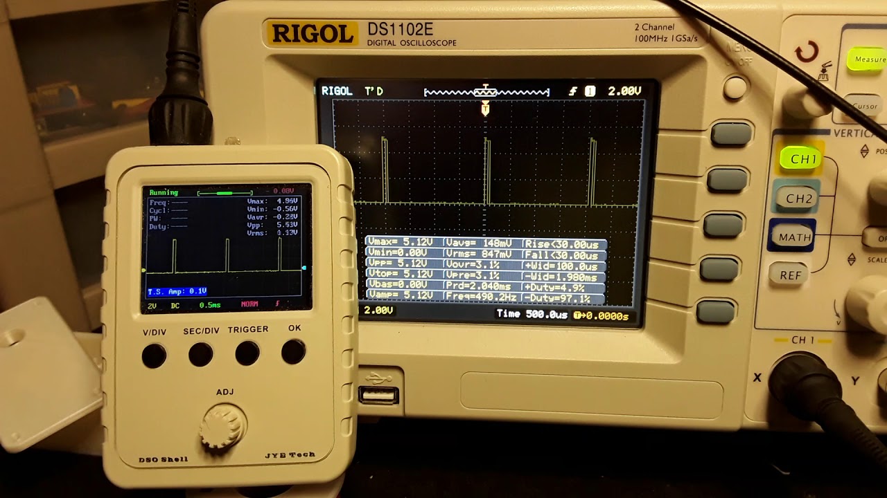
A far cheaper alternative, without the frequency response of the Rigol – but with plenty for this kind of work – is this little < $20 unit from Banggood displaying the same M106 S192 waveform (washed out from the flash but quite bright and sharp in normal light) from my post above

[attachment file=87978]

Waveform still captured!

[attachment file=87979]

You can find it here… both as a kit and also assembled for a few $$ more…

https://usa.banggood.com/Orignal-JYE-Tech-DS0150-15001K-DSO-SHELL-DIY-Digital-Oscilloscope-Kit-With-Housing-p-1093865.html?gmcCountry=US&currency=USD&createTmp=1&utm_source=googleshopping&utm_medium=cpc_bgcs&utm_content=zouzou&utm_campaign=pla-usg-ele-diy1-pc&cur_warehouse=CN

This little unit is really quite impressive IMO and definitely a help for this kind of work.

– David

2 Likes

Alright… after a day of much hair-pulling and most of a bottle of Merlot, I’ve (I think) figured out how to duplicate the RAMPS laser modulation signal with a mini-RAMBO board. I still need to actually hook it up to my MPCNC and do the engraving but, judging from the signals I see with my scope, I should be good to go. I’ll post those findings later.

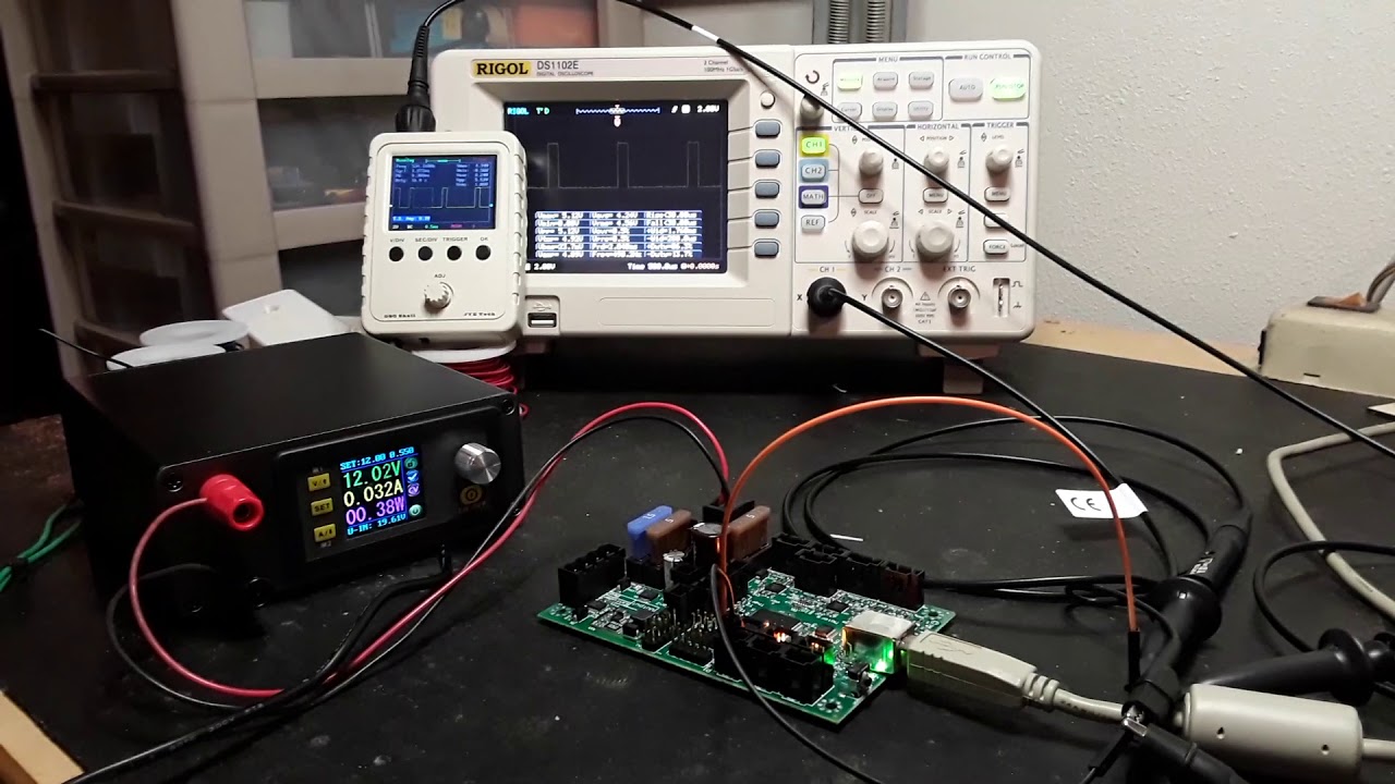
But, since we’ve touched on “scopes” and their suitability for the low-frequency work we’re cussing/discussing here… here’s a “sales job” for those of you so inclined – a side-by-side comparison of a $20 Banggood scope and my ~$300 Rigol DS1102E while running the Garfield raster engraving file…

The setup… mini-Rambo, displaying a +5v version of the FAN1 signal, remapped to Z-MIN

Close-up of same…

Now to go hook it up and test it on the MPCNC :wink:

– David

2 Likes

So, the $300 one is the one that fits in your (90s baggy jeans) pocket, not that big clunky boombox, right? :smiley:

Well, I’ve gotta go get another bottle of Merlot…

Bad news… or good news… depending on how you look at it :wink:

Got the mini-Rambo hooked up and running the Garfield file. But instead of the nice sharp engraving that I’ve gotten before… it now looks like the ones the Heath and Kelly have been proudly displaying. So, the mini-Rambo doesn’t seem to be working the way I’d hoped, but… on the other hand, I’ve duplicated what Kelly and Heath have been seeing. So, at least, I now have something to go play with…

No more hair… I’ll have to rely on the Merlot.

=8^(

1 Like

So, what is the frequency of the PWM? That was jtech’s guess about the problem.

And what version of Marlin were you using to get the crispy garfield, David?

Just to be thorough. Guffy found this earlier, and Aaryn just pointed it out in another thread. If using the M3/4 commands, using O instead of S (M3 O255) bypasses the mapping of values and you can use 1-255 instead of all the other spindle related things. Just making sure O is being used.

I am kind of at a loss here, why would the PWM be any different, hardware or firmware?

That $20 scope is awesome!

Z max right?

I feel like we’re finally getting somewhere now that we have reproducible results. I hope it leads to a solution.

That scope is amazing. I’d love to get it to aid in troubleshooting this issue, but I don’t know that I would ever use it after this and I hope to have this resolved well before it would make it here on the slow boat from China. For only $20 it’s still tempting.

So I just flashed the mini firmware, enabled the laser in config adv, used pin 10 in the pins file (laser), tried m3 o(0-255) and I get a wonderfully clean signal. Probes on Zmin signal and ground.

David what did you do that you get that bouncy signal?

(side note why the heck do I have Zmax and pin 23 everywhere?)

Jeff, the two short videos were showing the PWM period as 2 ms, so 500 Hz, for the mini-Rambo. And that matches what I was getting with the RAMPS. My MPCNC still uses all-thread and is using the old MPCNC813-GLCD firmware, with the D9 fan output remapped to pin 44. This setup has been running very well for a couple of years.

A recap from yesterday, as best I can remember… I tried so many things…

The mini-RAMBO… I couldn’t tell what firmware was flashed on it when I purchased it from Ryan a year or two ago. But since I needed to play with the laser and would be remapping things anyway, I downloaded the Marlin-MPCNC_MRambo_T8_16T_LCD firmware from github, got it compiled and flashed, and started probing around on the various pins while out on the work bench.

I spent the better part of the day looking about and reading, trying to find good information about where all the pins are physically located on the mini-RAMBO board and checking out signals with manual gcode input and the scope. I finally found the best information and schematics on the Reprap.org site, so I started playing around with both the FAN1/FAN2 outputs and the SPINDLE_LASER… stuff.

I did indeed play around some with the M03/M04 gcodes, which seemed to PWM the signals alright, but appeared “inverted”… with M03 S127 giving 50% duty cycle (DC) as you would expect but M03 S192 gave 25% DC, M03 S64 gave 75% DC, M03 S255 gave 0% DC, and M03 S0 gave 100% DC. I did exercise the Oxxx option a couple of times IIRC, and it varied the DC, but on the scope was indistinguishable from the Sxxx option. Also, what I’m calling the DC here is “time HIGH over the total period”. What I actually saw as described above, appeared to be “time LOW over the total period”… more an “active-low” vs “active-high” sort of thing.

Finally, I started playing with the FAN signals and see if I could duplicate what I saw with the RAMPS board… using the M106/M107 commands. I was finally able to get the FAN1 signal remapped to Z-MIN (the MIN signals are PWM pins, according to the compiler IIRC) and it seemed to exactly match what I’d seen on the RAMPS setup. This would also allow me to use the exact same Garfield file to test with…

So I slept on it and was pretty confident, this morning, that I could duplicate what I was getting with the RAMPS setup. But, no…

So that’s where I am now. I’m going to play around with it some more… now that I’ve got my teeth into it and can duplicate what Heath and Kelly have been seeing. I’m also reasonably confident now that I can remap signals/pins and handle compile errors when I see them. I am a bit bum-fuzzled about the mini- board not working as I expected it to, however. I’ll also probably hook the RAMPS back up and verify that it still works.

So, there you have it. I’ll keep you posted.

– David ,

Is there a simpler gcode file that we can use to see the issue more clearly?

You guys are going to make me put my laser on the LR, aren’t you?

Ya’ got me… :wink:

My signals on the mini-RAMBO were clean as well… looking identical AFAICT to the RAMPS signals. But they definitely don’t actually engrave cleanly, whereas the RAMPS version does.

The “bouncy signal”? Don’cha love it when people talk “technical”… :wink:

If you’re talking about the two “scope videos”… that’s the laser’s PWM signal WHILE ACTUALLY RUNNING the Garfield file; i.e. that’s not a manually-input static gcode command.

I think there’s a ton of suspect information out there, Ryan. I found it terribly difficult to find useful information yesterday regarding the mini-Rambo’s pinouts… finally settled in on the Reprap.org site, working from the schematics and silkscreen markings on the board photo. It was quite frustrating.

Also, the compiler will let you know if you’ve tried to remap to a non-PWM pin…

– David

Yep.

Pins (we use the arduino numbers (I double checked)) -https://reprap.org/wiki/MiniRambo_development

most locations-https://reprap.org/wiki/File:MiniRambo1.3a-connections-p1-p2-p3-digital-pins-labeled.png


So I guess the next step is try a few of the available PWM pins-with a real file. Dangit, I am going to have to stink up my office and open a window in this freezing weather (cali…like 55 degrees).

One more data point…

I’ve actually got another laser engraver – an Eleksmaker A3 – that I put a Banggood laser on and set it up with Marlin/RAMPS just like the MPCNC laser machine I’ve been using for these tests. For grins, I ran the exact same Garfield file on it as well… physically different machine, physically different RAMPS… and got the same nice crisp result as from the MPCNC…

[attachment file=88158]

[attachment file=88157]

I’m really beginning to believe there something “squirrely” (more technical talk!) with the mini-Rambo board… it may work, under the right conditions, but I’m clueless at the moment as to what those conditions are. Here’s my test run, from this morning, using the mini- board…

[attachment file=88160]

Look familiar?

– David


I still think there’s something that’s breaking this in the software versions. The latest 2.0. from Ryan has something that’s killing this, and the previous 2.0 didn’t have that problem. Something in the motion code isn’t doing the same thing. It’s hovering more near the endpoints, or something.