I had to read that about 4x before I realized you were doing relative movements… I need more coffee.
I vote for some binary code on the edge to write down the distance ![]()
I had to read that about 4x before I realized you were doing relative movements… I need more coffee.
I vote for some binary code on the edge to write down the distance ![]()
I love learning! This is so great.
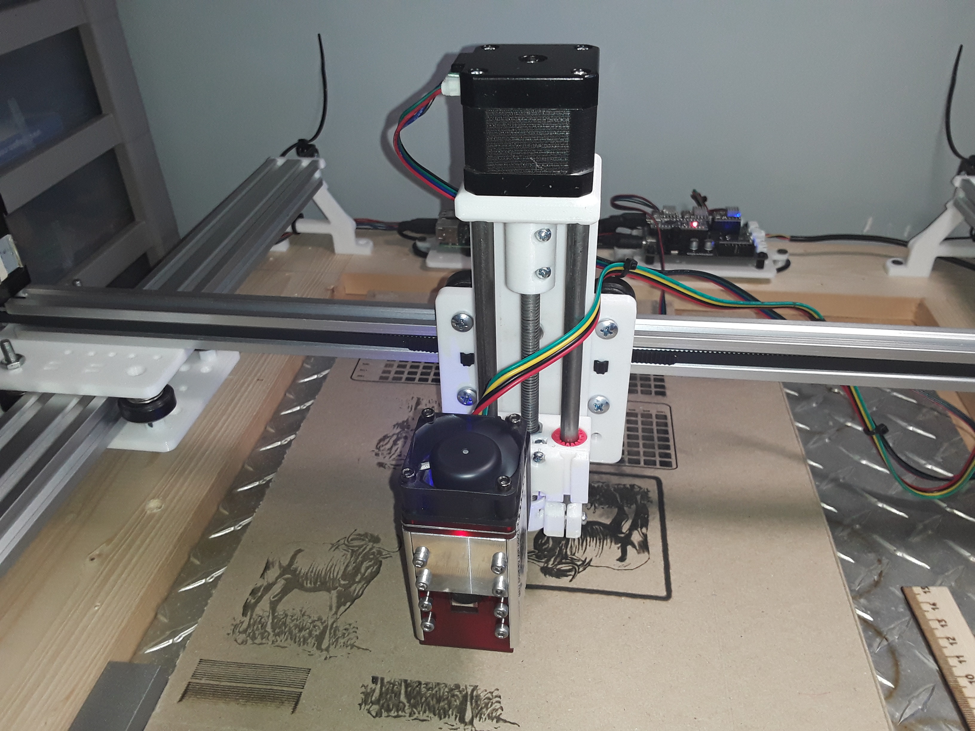
I ran it and if I’m understanding my results I was only about 4-6mm off. Not bad for a blind guy. I ran it three times back to back and am glad I did or I might have missed the full ramp of widths. I just shuttled the X back 50mm before the start of each pass. I bumped the Y +2 as well but didn’t need to do that.[attachment file=86414]
how you like that? )
M106 S255
G91
M98 P999
M98 P999
M98 P999
M98 P999
M98 P999
G90
M107
M30

O999
G0 Z2 Y1 F440
G1 X50 F750
G0 Z2 Y1 F440
G1 X-50 F750
M99
this could be possible if our firmware could be able to support subprograms like Fanuc controllers
Nope. That’s cheating.
Added this to favorite to circle back and re read later to verify my Edurance 10w setup once I build my new frame/bed. Thanks guys!
KellyD,
I’ve got old, tired eyes as well but it doesn’t appear to me that you’re really finding the focal “sweet spot” using Ryan’s focus script yet. In my experience, there should be very distinct “gradients” over the 20mm range of the focus script on either side of best focus… similar to the 2nd photo in my post above.
An easy way to find the “sweet spot” is to run the lens down very close to the material (within just a few mm of the surface)… and then run Ryan’s focus script several times in succession, without readjusting Z between runs. [You might want to set up a fan to blow across the work surface… especially when the lens is very close to the surface of the material.] Somewhere in there you should find the beam gets really focused – the “sweet spot”… take note about where the Z axis is when best focus is achieved.
The lasers I’ve gotten have all come from the factory focused way too close for use with a shroud (which I highly recommend)… so I screw out the lens assembly to get best focus at 50mm - 55mm from the lens (usually only a few threads are left to hold it in place in the heatsink).
– David
The literature that came from JTech suggested that they were “set from the factory at 3” so that’s sort of the neighbourhood I’ve been playing in. I’ll run it right down and do as you suggest. I’m definitely not seeing the sort of gradient you are. Thanks for digging deeper for me. I’ll post a pic of the results.
I think I had some fingerprint oil on the wood? In any case, here are the results. Z-0 was about 15mm from the material surface hence the -10 on the second run.
Nothing close to the variance your pics show…
[attachment file=86443]
[attachment file=86444]
The first photo really doesn’t look too bad. I would say that the line or two left of your “50” (mm?) mark looks like best focus. To the extremes, left and right, don’t worry about it… it’s so far out of focus, there’s not enough energy to burn the surface. 50mm is also closer to 2" than 3"…
My photos above were done on cardboard, yours on wood… maybe that’s part of it. Are you running the original script… at full power, with lines spaced 1mm apart in Y, and Z increasing by 2mm with each line? I’m also not a fan of the continuous, bi-directional scanning… it ties lines together and burns the end of the lines, where often the greatest contrast in line width can be seen IMO.
I would set the Z at about 46mm or so from the material and then run the script once. That should put best focus near the center of the pattern. Count lines back to the finest/thinnest line, multiply by 2, and then lower Z by that amount. You should be good to go.
– David
Thanks again David. I appreciate the second set of old man eyes. That was the continuous gcode with slightly different feed rates. I’ll try the original one (with Ryan’s suggested speeds) on cardboard and see if I can set the material surface at zero (I imagine that’s the smarter way to do this).
That’s more of a gradient for sure (cardboard).
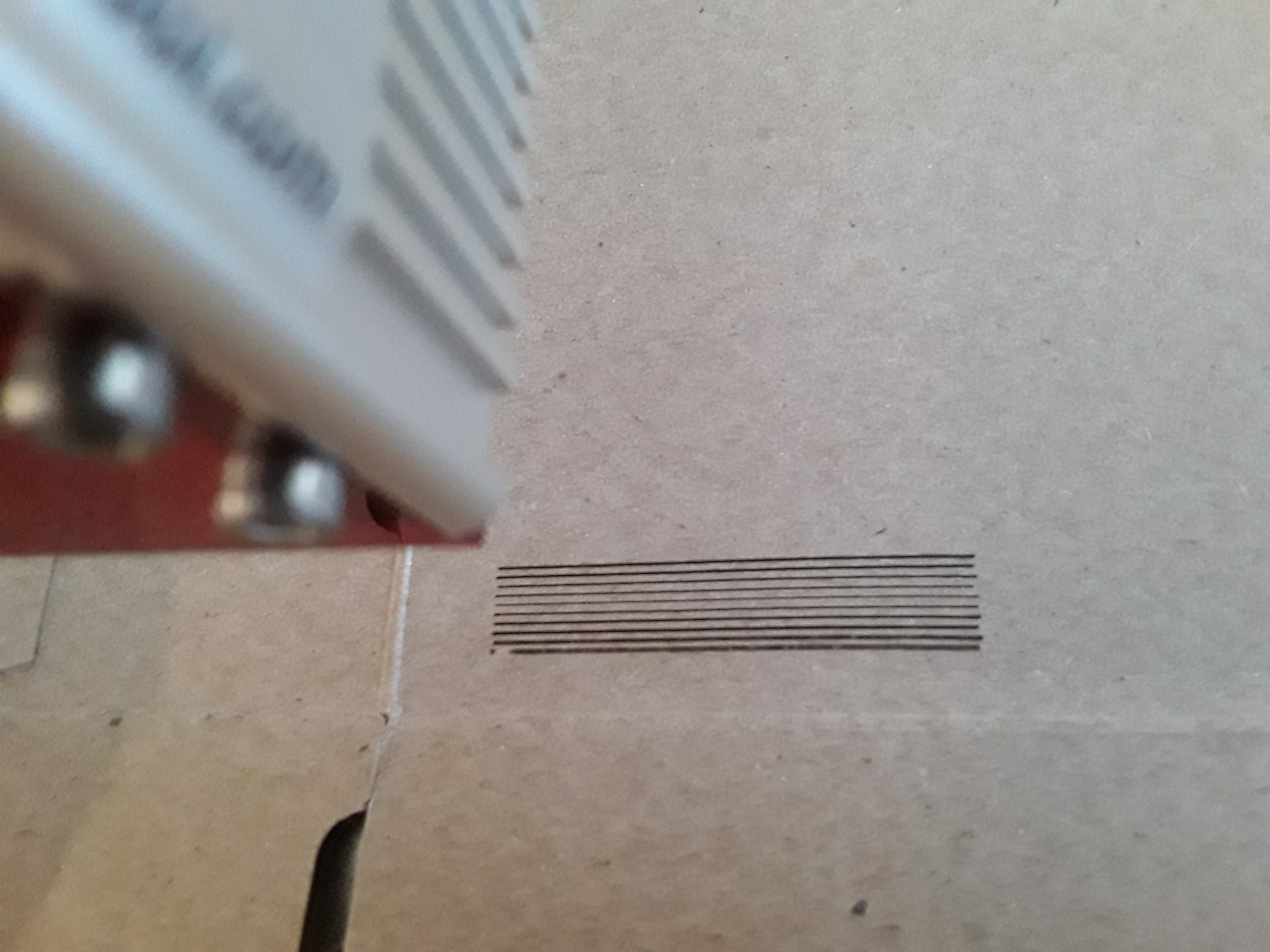
So to try to understand more of what you (DJI) said above there…you find your ideal focus and then run cut through tests using that focus but speeding or slowing the moves to find what speed cuts through for you?[attachment file=86480]
Exactly. Ryan’s focus pattern shows variation in line width due to focus, a function of Z, at fixed speed and power. The 10 widely-spaced lines (the 2nd run in my photo) are to determine feed/power to through-cut the material, and shows a variation in line width also… however, now it is a function of the feed rate, at full power and best focus. The idea is to find the fastest feed, at a given power, that gives a clean through-cut, with minimal charring of the edges; i.e. the cut pieces in the later photos were cut in a single pass at 100 mm/min and show little/no charring of the edges.
– David
BTW the craft stick honeycomb “trivets” the cardboard is resting on in my photos were also cut with the laser in the same fashion… a single pass and 100 mm/min IIRC. Each 1.5mm thick craft stick (I think they are bamboo…) took less than 2 minutes to slot… allowing time for assembly while the next stick was cutting 
[attachment file=86490]
[attachment file=86491]
[attachment file=86492]
[attachment file=86493]
Thanks for the tip! I’d been thinking about that as I was “playing”. I modified Ryan’s crown to play with papers and cardstocks. I had to go down to 25% feedrate (on the LCD) to get it to cut through the 100lb cover weight stock. I wondered if it might have cut through better/faster if it wasn’t sitting on a solid surface (cardboard). 50% federates almost went through but not quite.
The laser turned back on (and turned off) partway through the z clearance moves - which I know I didn’t need…so I removed them from the attached. In case others want to play with the file. Note I haven’t test cut this but at these rates I was able to go through standard copier paper at 100% speeds.
LaserCrown.gcode (80.9 KB)
Did someone make a GRBL version of this code?
……
okok, 18 to 26 mm 600 mm/s 70% (mine was spot on @ 21mm)
grbl-focus.gcode (497 Bytes)
M3 inline 2mm Z steps test file
You can use this and replace the “Z2” with a smaller number to really try to dial in your focus.
G1 X50 F750 S255
G0 Y1 F6000
G0 Z2 F2000
G0 X-40 F6000
2mm focus.gcode (933 Bytes)
Is this linked in the docs?
Not yet. Still messing with it. Not sure if inline is the best option yet. Each one seems to have trade offs.
I tried using Kees’ script, and had to make a few changes to work with GRBL laser mode ($32=1) and M4. If MPCNC is headed toward esp32 and grbl, using M4 is the proper way to script for laser IMHO. I also realized the workflow of operating a laser, is easier if a simple height jig is used to set z0 before starting a job. That being the case, the lens has to be tuned for a specific height, which means the script works best if it repeats the same height range around z0.
Before I run my script, I set z0 to the desired focal length (my 40mm custom lens cap/jig). Then I run the script, looking at the lines and tweaking the lens between runs, until the center Z=0 line (easy to spot as it is 5mm longer than the rest) is centered in the sweet spot.
Besides making the script look cleaner, and not having the starts/ends of the lines look overburned, using M4 allows me to keep my airbrush compressor from toggling on and off between each line. I use a spindle relay for my router and my airbrush compressor. Since M3/M5 toggles the spindle on/off, the compressor goes on off together with the laser. Using M4/G0/G1, the compressor stays on until I call M5 at the very end of the script. Lightburn does it the same way for GRBL. On a side note, M8/M9 is also needed in my case to open/close an air valve. I have a single set of airlines I use with both the airbrush compressor (for laser) and a larger regulated compressor (for alum mist). So while the valve isn’t needed for the airbrush compressor, it still is in the way and has to be opened when it turns on. Another side note, GRBL currently defaults with a max spindle value of 1000. So 255 is actually burning at 25.5% power, unless you change the max spindle rpm in settings from the default 1000.
I was thinking how to get more precise… maybe once you get past 1mm steps, reduce power until it only cleanly etches the center lines, then up the resolution to like 0.5mm or even lower. That way seems like it would work better for human eyes to see a clear cut difference at finer resolutions… keep reducing power and looking for cut/no-cut until you get down to only one line at 0.1mm. That said, 0.1mm may stroke my OCD, but the difference between the center few lines at 1mm is hardly noticeable… so not confident that focusing any tighter than 1mm has any advantages.
laserFocusScript.gcode (947 Bytes)
I have a Grbl/M4 (laser mode) script that is used exactly as Ryan’s original script… and assumes the lens assembly has already been positioned for a desired focal length (no further adjustment required) and you have a fully-implemented, gcode-controlled, Z axis.
To use… initially – and intentionally – set Z “too close” to the material surface for proper focus and then run the script. It draws a series of 10 lines… with each line displaced 1mm in Y and 2mm in Z from its neighbor. At script end, you are 10mm in Y and 20mm in Z above where you started. Now, simply count lines back to the finest/thinnest (best focused) line and multiply by 2mm… and then lower your Z axis by that amount for best focus on the surface of the material.

Here the 5th line from the top is finest/thinnest (to my old, tired, eyes)… so I lower Z from its current position by 10mm (5 lines X 2mm) and I now have “best focus” on the surface of the material.
The script is easily edited to change speed and power for your laser and material… here, it is set for 600 mm/min and 25% (S250) power.
M4Focus.zip (473 Bytes)
– David