So I’m currently trying to setup my 3.5W Banggood Laser that uses 5V TTL and am at the process that I need to assign the correct pins. From my understanding and because I am using the latest dual endstop firmware for my MPCNC that using the M3 commands are not available and that I need to reassign the Fan 1 pin to pin 45 to send M106 SXX commands via a 5V TTL command. I am confused for two parts of that.
When I am reassigning the pins in pins_RAMBO.h does it look like the screen shot that I have attached? Or do I need to make additional changes? In configuration_adv.h I have #define_spindle_laser commented out.
If I'm wiring to pin 45 on the rambo board does the ground signal go to pin 31 aka Spindle_laser_enable_pin or do I need to find a ground for the TTL signal?
I have taken into account the 10Hz fix in the Marlin.cpp code
Please let me know if these questions are confusing. I have read all documentation on here but still am a bit miffed and want to make sure I'm doing it correctly.
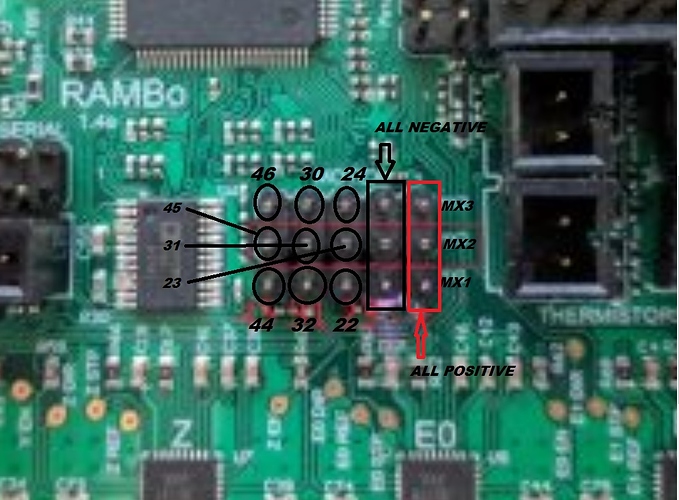
#1: The RAMBO board actually has 3 fans, so in pins_RAMBO.h there are 3 pins defined for the 3 fans. Fan 0, which would be for the main 3D printer extruder if the board was used for a 3D printer is assigned to Pin 8. I reassigned that pin to pin 45 which is a PWM signal pin that uses 5V at its max PWM signal.
#2: Pin #31 aka #define SPINDLE_LASER_ENABLE_PIN 31 is an output and will fire 5V to the board. This is not a ground. For proper wiring you need to have your +5V PWM signal (red wire) go to pin 45 and your GND (black wire) go to the (-) pin located on MX2.
I reloaded the firmware, sent the M106 S255 and M106 S128 signals respectfully to the pins and got +5V and +2.5V off the pins.
When I tried to test on the laser itself, with only having the 12V on the laser and no TTL signal I would get full blast laser. When I tried to put the signal on and activate the code I would get nothing. I measured the signal coming from the pins onto the TTL cable knowing that it had 5V on it and was reading 0V. This meant that the signal was being pulled to ground. After reading a few posts in the 2.8w $100 laser setup I noticed that it said some of the polarities are switched and sure enough, black wire on the laser was the 5V PWM signal and the red wire was the ground. Swapped them and was able to use the M106 and M107 commands and the focus script to get a few cuts.
This took me back (2 years ago) to my troubleshooting as a FSE days. I’m not saying I was good at it but I enjoyed it going through the schematics and figuring it out.
Hi,
I have rambo 1.4 board and all seems to be working fine. Although when I tried to use the M03 M05 comands pin 45 does not show up as a PWM signal. All i get is a 50hz pulse at about 50 % duty that doesn’t change going from 0 to 5v- it looks like mains interference. Is there any thing I’m missing here?
So I was thinking of swapping the fan0 pin 8 to pin 45 - as this seems to be the only way I can get a PWM signal at 5V TTL - which is where I ran into issues. I downloaded the “Marlin-MPCNC_Rambo_T8_16T_LCD_DualEndstop” from github but ran into a compiler error, something about the LCD… What version would have been pre-load onto the rambo pcb before it was shipped to me? I ordered the dual endstop version. When I start up the board it says “bugfix 2.0” is that the firmware version ? Should I download and change the pins on that firmware instead? Will it support dual end stops still.
Use my links on the firmware page. It also gives the lcd solution in the step by step.
As for the pin change and laser it is dependent on what you bought and what edits you make in the firmware. Currently using a fan command and fan delay fix works best. All found on the laser page.