I know that someone on here mentioned this before, but I can’t find the post, and I don’t think there was an answer, so I thought I’d ask again, since I’ve just run into the issue.
If I create an image that is a simple outline of a square, and generate gcode of the image with LaserEtch, it will burn the image like a raster, line by line. This means that for most of the burning time, the machine is traveling and burning like this (each blip is burning a single dot, which is part of the square outline):
blip …travel to the other side of the picture … blip
blip …travel to the other side of the picture … blip
blip …travel to the other side of the picture … blip
blip …travel to the other side of the picture … blip
The most efficient way would be for the machine to just turn on the laser and draw the square, rather than build it pixel by pixel on opposite sides of the burn area.
So I guess I’m looking for a program with better toolpathing for lasers. I could not get the inkscape plugin to work, and I haven’t been able to figure out how to set up the laser as a tool in ESTLCAM.
Any tips on how to get those tools working, or suggestions for other tools - preferably open source or at least not too expensive - would be greatly appreciated!
Unfortunately this is something you won’t be able to do too much about. The MPCNC firmware set-up will control the laser with the M106 and M107 commands . A better way to go is to use the M03 and M05 spindle commands to drive a laser. Then you just have to set up your CAD/CAM software to use a certain spindle speed with any given tool, and set the tools size to the beam diameter of your laser . The M106 and M107 commands don’t really work for this.
And you’re correct, the LaserEtch software appears to be raster based but doesn’t even support grayscale so it’s not very useful. Definitely need a vector based solution.
Good points, Leo! Makes me wonder, though - maybe I could set up a tool with spindle controls like you mentioned, then doctor the resulting gcode, replacing the spindle commands with M106 commands.
I also sent the question directly to Christian, the author of ESTLCAM, just in case there’s something in settings that I’m missing.
I was looking at the marlin firmware source files again. They are very new to me so maybe an expert can chime in but I’m not seeing the mo3 and m05 commands being processed at all by the interpreter.It should be pretty easy to modify the code to process these commands and remap them to the same finctions used by the m106 and m107 codes.
Then your laser would fire with either the m106 or m03. The m03 is definitely better and more cad/cam friendly. If your software allows you to set tool size and spindle speed then you’d be back in business. You’d also have to set the the tool to make only one pass of course.
If no one else volunteers then I’ll try to look into this in the next day or two.
I heard back from Christian. Turns out there was a new version of ESTLCAM released on 12/24/15 that has settings in it for laser! I will have to try it out tonight. The new settings are found in Setup > CNC Program Generation > Texts > Lasers, etc.
Note: I downloaded and installed the new version, and it overwrote all my tool settings and preferences, so beware!
I’ve learned one thing so far: if you want easy, consistent burns, use the rasterized approach, which burns the image a line at a time, never burning the same spot twice, or spending too much time in one area. I might be able to get decent results eventually, after much tweaking of speed, stepover, and power, but I was surprised and disappointed at my first attempts at burning a non-rasterized image. The main problem is that, unlike a router, which can zip back and forth over an area to clear out a pocket and only removes material as it encounters it, the laser continues to burn and re-burn as it moves, so ideally, the laser should never pass over the same spot twice, at least not while it’s on.
That’s my observation after just a couple of attempts using ESTLCAM. I used full power, 800 mm/min, and 80% stepover. I have the tool size set to .1 mm. The laser spends too much time filling in lines, and just chars the whole area. If anyone has any experience and suggestions, please let me know. I’ll be giving it another try tonight, but for my next real project, I think I’ll need to stick with the rasterized images.
One other thing - I finally got the inkscape plug in to work! You have to have the latest version of inkscape (.91), which was my problem until I updated it.
I like the looks of the code it produces. It apparently only makes gcode for the stroke paths - at least that’s what I’ve gotten so far, with three tries. This could be good, if you wanted your objects with no fill, or you plan to paint them later. The gcode simulator I ran the code through says the runtime is <10 minutes. I’ll give it a try tonight and report back.
This is good info Karl.Keep it up. The only experience i have with vector lasering is creating pcb layouts with my diptrace software which exports in dxf format. I think i used cambam to actually generate the gcode but it was with the M03 and M05 codes.
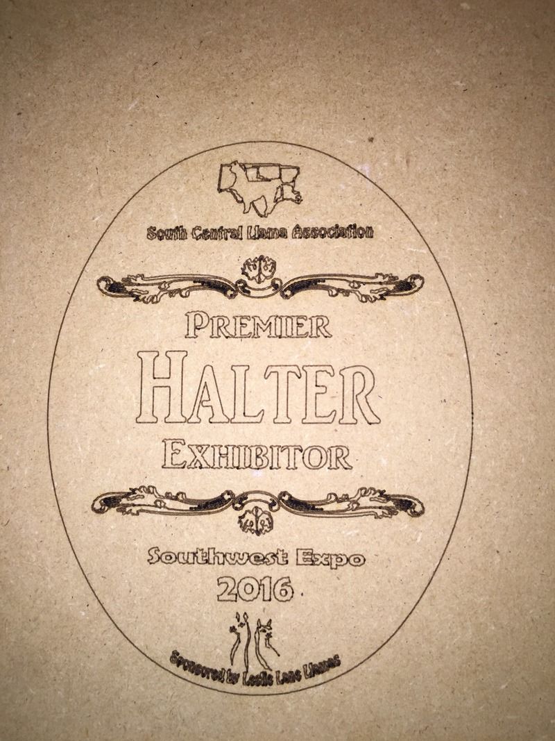
As I thought, the vector burning burns the lines and ignores the fills. This will be great if you want to burn outlines to paint in later, or are doing line-based designs. The stipple thing somebody was doing with a pen in another thread would be a good candidate. The vector burning was also very quick - less than 10 minutes for the 6-inch tall oval shown here. The vector code was generated with the inkscape plugin.
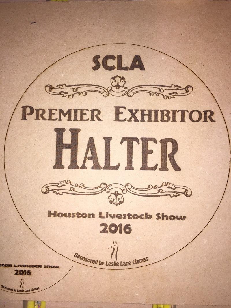
The other burn is an earlier version of the same plaque, round instead of oval, and 9 inches tall. It was burned with the raster style. As you can see, the raster style is more consistent overall and has great detail. It also took several hours to burn, so there are trade offs with each style. The raster was generated with LaserEtch.
Wow.Very nice detail.It looks like your laser is well focused. I’ve been reading about a nice open source vector software called Visicut but their download link is down. The YouTube videos I found showing camera integration look interesting. Check it out.
I’ve been using Easel from Inventables for vector based work, only because I’m used to it. It does have its limitations since it’s very much a CNC router app. Tweaking of things like bit size and stepover are also important there.
I then export the gcode and do a find/replace for all the router M03/M05 style commands and add M106/M107 every Z up and down (zup to move to a new part…M107 laser off), Z down to start cutting new object…M106 to turn it back on.
Wow, this thing came out great! This was my first burn on anything other than MDF. These are pine plaques I got from Amazon, but are available at any craft store.
Pine burns much more easily than the MDF. These burns are easily 1/16 deep. I’m very happy with how this turned out. Tomorrow I’ll see what I can do to remove the charring around the edges.
Great work Karl.
I have been too busy with a remodel project to be able to work with my CNC or laser. The little work I have done I have used my LCD display to control the CNC. This has been helpful since I can adjust the speed easily to help me better understand the proper speed for certain power settings. Hopefully next week I can get for time in to learn more. Also thanks for the tip on the Inkscape plugin. I could not figure out why it worked on one laptop and not another.
Curt
I have another burn going now using masking tape - we’ll see how it comes out. Note when putting on the tape - you should butt the edges together, and not have any overlap at all. I know that probably sounds obvious, but I thought that 1/16 of an inch overlap wouldn’t hurt, but it kinda looks like it did - I’ll know for sure when the burn’s finished.
For this burn I mounted my mobius camera on the z tower, so it moves with the laser. It’ll be interesting to see what that looks like.
Curt, can you control the speed from the LCD while it’s burning? I know if I turn the knob when it’s not running a program, the feedrate will change, but it wouldn’t do it while it was burning. It would be helpful to be able to tweak it without having to stop.
I am using a 20x4 LCD and while it is running I can adjust the CNC speed with the knob. It starts out at 100% and I can go up to at least 300% and down to 0%. It has been helpful when I had too high of a speed when I was routing and I was able to slow it down.
When I did my test burn of Ryan’s logo you can see on the small one that the web address is not readable. This is because I had too much power or too little speed. I sped it up and the rest looked better. I then changed the speed in the laseretch software to the desire speed before I burnt the larger one.
I still have a lot to learn and I really appreciate the information you are sharing!!
We’re all learning, Curt! I’m just focusing on this right now because I had promised to make these awards for an upcoming livestock show.
I am also using the 2004 LCD and this afternoon found that I could change the feedrate while running a program, as you said. It just takes a couple of turns before it starts changing, which is why I thought it didn’t work when I experimentally gave it one click each direction - I didn’t want to risk messing up the burn at the time.
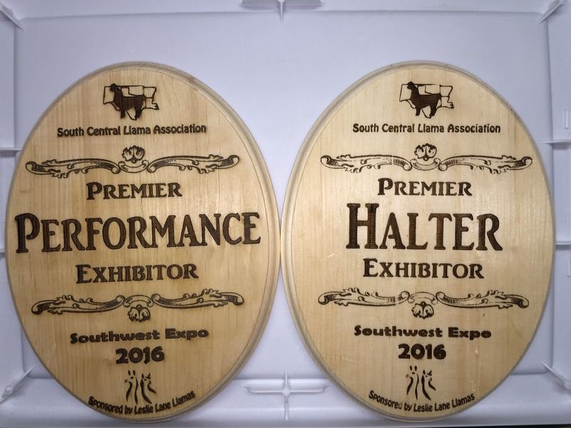
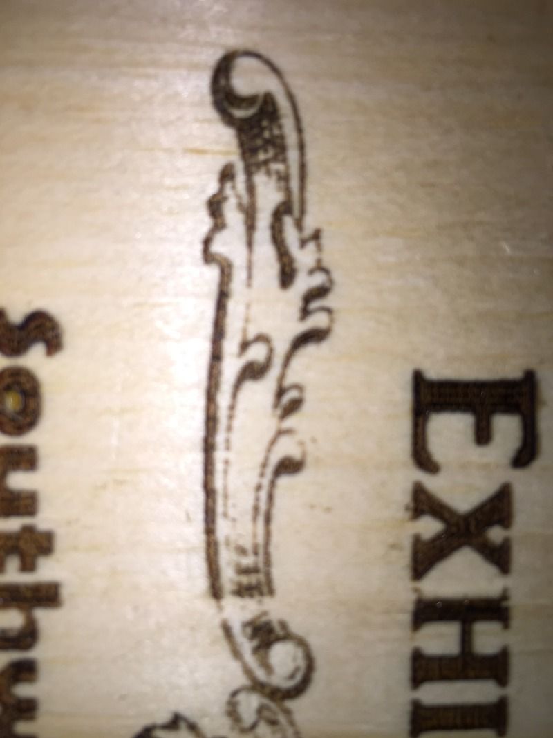
I did another burn using masking tape to reduce charring. It absolutely does reduce charring, but I would only do it if what you’re burning is not too detailed. Big bold letters and graphics would benefit from using tape, but if you have a lot of small text, or detailed graphics, getting the tape off is tedious, and fine lines sometimes do not burn all the way through. They end up looking like a bad rubber stamp. I guess you could slow it down - maybe I’ll give that a try another time. Here are a couple of pictures to demonstrate what I’m talking about.
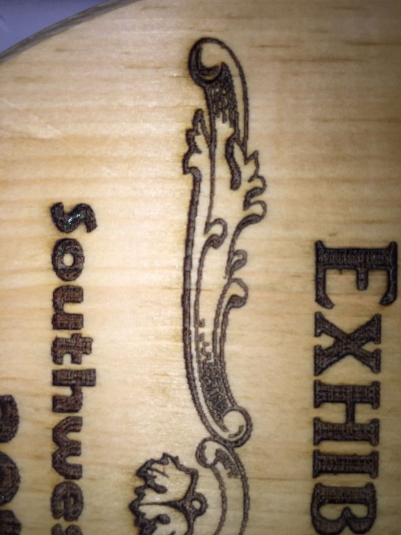
The one on the left was burned without tape. I cleaned up the charring with denatured alcohol. I’m hoping that staining will cover any remaining discoloration. The one on the right was printed with tape. There’s no charring, but note the loss of detail, especially around the scrollwork.
The laser driver is set to 1.8 amps, which translates to 2.3w at the laser (based on JTP saying that 1.7 amps is 2.2w). By the way, I intend to add a couple of test jacks and a switch that will disconnect the laser and connect the test jacks to the driver output to make it easier to set the amperage next time.
I’m only doing one pass at the moment. Other materials might require more. I haven’t tried cutting yet, but I bought a sheet of the laser shield, and I’m going to laser cut a piece to attach to my laser mount.
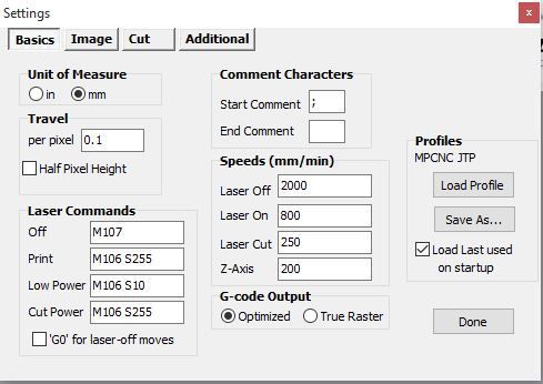
LaserEtch Settings:
So my speed for laser etching these plaques was 800 mm/min. When I did the pictures earlier, using image2gcode, they were going at 1000 mm/min, I think.