So I guess that means, I should have used one of the 3.3V ground pins…like the one directly next to the signal pin I am using.
So the ground between the 3.3V and 12V is not common…I should have known that.
But you got me there. I can see the traces go straight to the chip but never put two and two together. Your comment somehow made me realize the 3.3V part. That is, if I am right about that.
Just checked my old Tek 275 scope, the probe ground is tied to mains ground. If you’re using one of your laptop like PS’s those are likely floating. Sounds like you didn’t connect the scope/skr grounds before probing signals, so I guess momentarily there could be enough charge to annoy the STM chip.
I doubt there’s a separate 12V gnd and 3.3 V ground on the SKR, I’m not seeing separate ones (at first glance) on the schematic.
The negative on the fan port isn’t ground. But I would be suspicious of you told me that the ground on the power in wasn’t the same as the ground on the skr.
It sounds like the missing bootloader problem I had on my board (for name changes, but it never runs).
I don’t think they are the same. I fixed mine with just a regular old uart to usb adapter. It attaches to serial port 1, and there was a windows tool. I ended up using the Linux tool (did you guys know I use Linux? You should try it ).
If that is the case I think it can be done with another arduino if I am not mistaken. I will look into it in a bit I am going to spend a little time with the rambo and a laser right now.
We already have established pins for the ramps, rambo, and mini. They all use the same processor so doing one means the rest should be fine with the same settings. From there I will define the pins in the firmware by default in our firmware but as is we have tested and know the pins work you just need to edit them yourself right now.
The isp can be done with another arduino. I am not sure if the arduino can be configured to totally get out of the way and just be a uart adapter. I haven’t tried that because the usb uart things are pretty useful and very cheap. You might have one for your quadcopters or something.
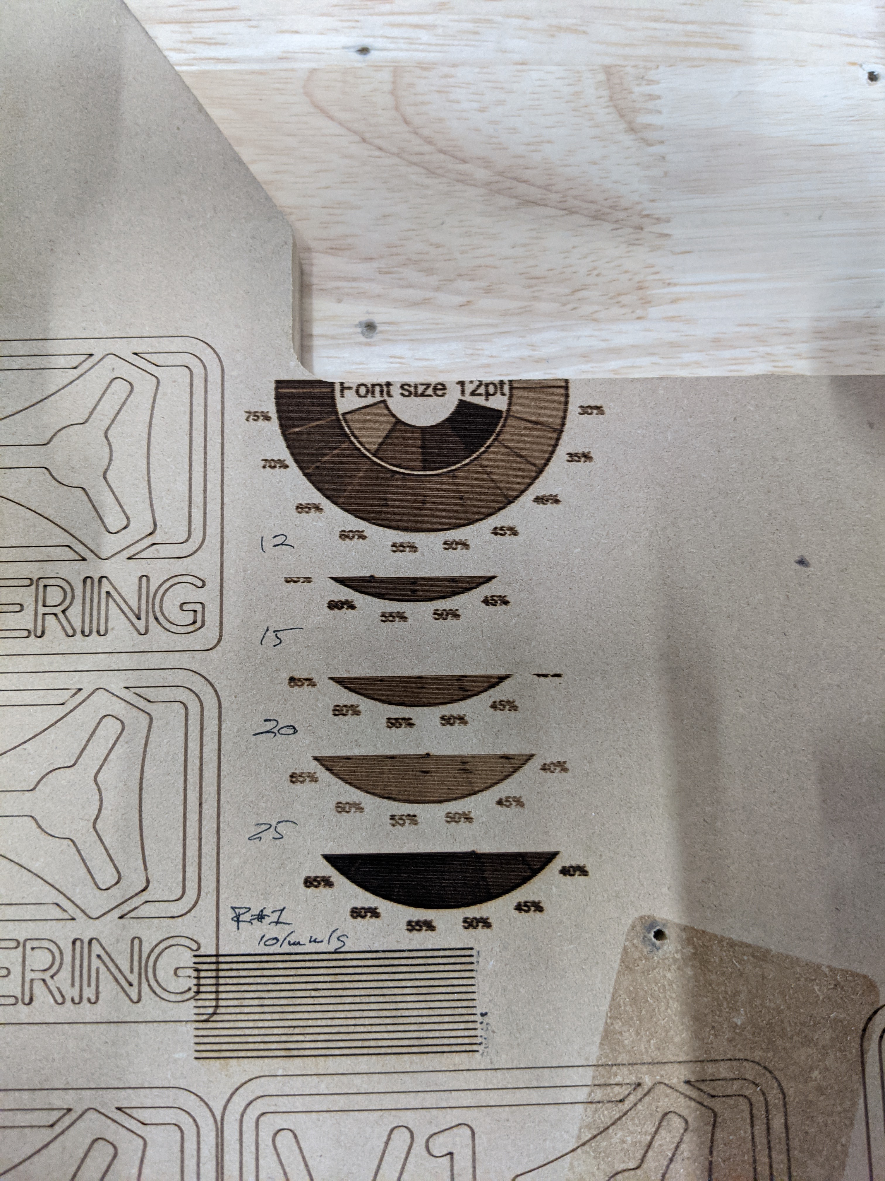
I am watching the Rambo burn…very slowly. I think I found the issue??? I am fairly certain the planner is accelerating the laser power changes. Which it should not.
I am careful to not have the speeds change from G1 and G0, but on top of that the color changes in the picture are stuttering.
The Rambo is doing fine at 10mm/s and a little wonky at 12mm/s but most of the glitches on it at faster speeds are at power level transitions.
Spell check does not work with laser glasses on, red is not visible.
25mm/s vector and it still stuttered, no power transitions so my previous theory was wrong.
It stuttered on the curved sections which are not arcs…so buffer or just something wrong with how inline commands are processed?
Are we back to small buffers? That was the compounding issue on the v1 logo. At one end, the arcs were crushing the cpu. At the other end, the many commands were causing the buffer to be starved.
It works just have to keep the speeds slow. I can’t automatically set the pins for the enable though. I was hoping the next pull request for the laser stuff would make it in soon to test again.
I was just using the fan port an m106/m107 to control the laser. To run inline can i just update the firmware and connect the 3rd wire to the servo signal pin, or do i need to move to one of the heater connections as well?
I used the one posted for the Skr1.3 last night and turned the laser part on. I had to set the enable pin for the fan and the servo pin as the pwm. I tried your file above and the laser doesn’t turn on, i can run old files using the m106/107
 I really want to add a laser