All,
(I’m not quite sure this is the correct category for this post, but please move it if it isn’t.)
Sorry for the long post, but I wanted to capture everything while it was fresh in my mind.
I finally got to cut my first real project, an Instrument panel.
In the process I dealt with a couple software issues (EstlCAM), mechanical stupidity, and getting the steps just right (which saved my butt when part of the cut failed).
Mechanical first: I’m using the Dewalt 660 and I while I saw something about using the builtin “wrench” to tighten the collet, I found that it is pretty worthless! I almost lost the whole part when the collet was too loose and the bit came out part-way through the cut. The bit is an upcut and it just walked itself down into the wasteboard, gouging the hole out of round. Fortunately I was able to get the bit reinstalled and because I had documented the setup I was able to restart the cut without any additional mechanical problems. Lesson learned: USE A REAL WRENCH TO TIGHTEN THE COLLET NUT!! It’s just really tough to get it tight enough with the nose piece wrench (which will be removed the next time I take the router off the mount).
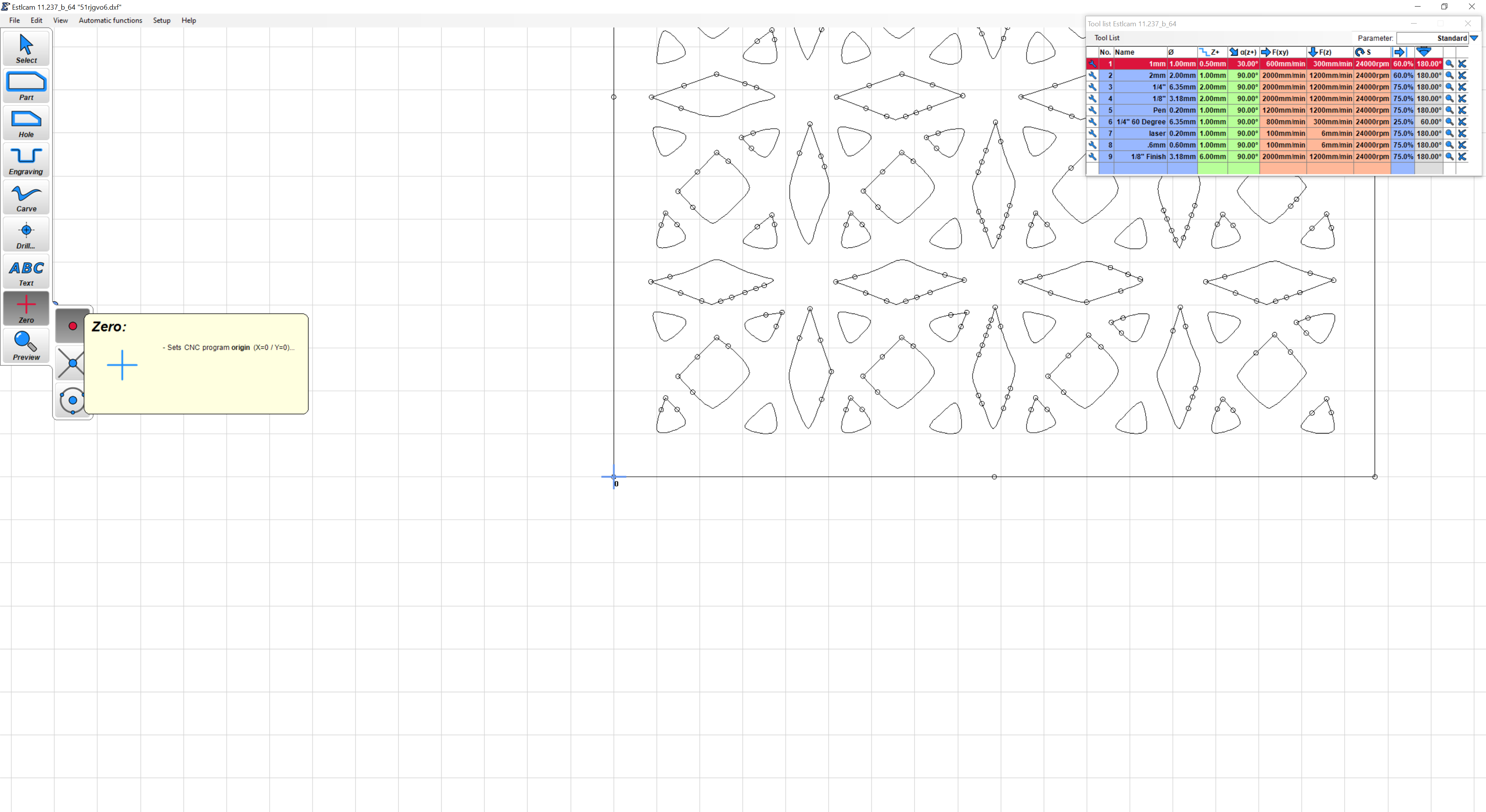
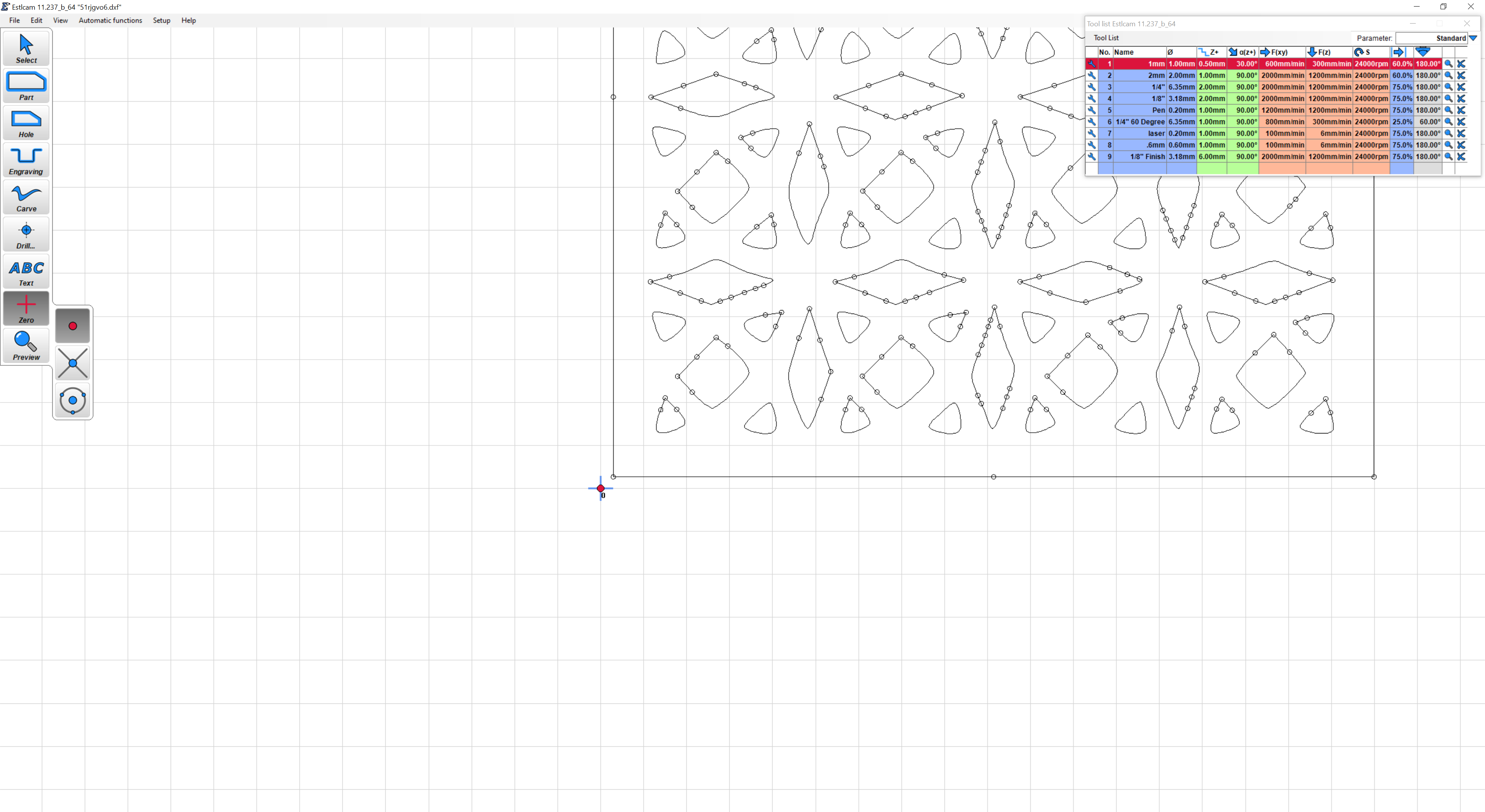
EstlCAM challenges: The first few cut attempts looked like an extreme slow-motion video. The head moved quickly to the location and then just seemed to make barely perceptible motions while making the hole. I went back over the settings in the EstlCAM Basics and one of the settings was not shown in the same way in the current documentation as the software shows it: Z-Plunge ramp angle. I had it set to 1 degrees, which is WAY too shallow. I reset it to 45 degrees and that seems to work fine. I suspect I can set it to 90 degrees and still cut just fine in my materials. Also Plunge depth and cut-depth have some funny interactions if they are not coordinated. I don’t yet have a complete understanding of how that works, but for the moment I can cut. Another EstlCAM foible is that when you first load a DXF file, it wants to place the tool path origin at the lower left point that is the extent of the drawing elements. I wanted my tool path origin to be in another location, further left and down (due to the way my non-flat part needed to be cut). I did this by adding a small circle on the drawing where I wanted the tool origin to be. I could then select that point in EstlCAM for the origin point.
Lastly, my setup, documentation, and work flow checklist. Two terms that I think make some of the explanation easier to understand: Machine origin is the location the core moves when I ask it to home (square) the trucks. Work origin is the location on the workspace that I want to use as the 0,0 point for the cutting. I mounted a smaller wasteboard for this project that I expect to reuse when (if) I do another panel for this glider type. I squared it to the table and homed the trucks, then moved the PEN to the point on the wasteboard where I wanted to start the cut (workspace origin). An important point here, this point will be the same as is shown in EstlCAM for the origin of the tool path. It is the one I selected using my added circle on my drawing. I then noted the machine coordinates (X,Y) for that point relative to the homing position. Now I can get back to it even if I turn the machine off. Using the pen I drew X and Y lines to help me verify that location in the future. I also made other notes for lines I needed to orient the part, but that is not part of the general work flow.
To start a cut I do the following at the MPCNC:
-
Move the core close to the machine origin (I need to get my machine size correct in the firmware as it does a reset if I try to home for too far away). You may not need to do this step.
-
Power up the machine and home the axis using the V1 Menu (I have a TFT display and am still using sneaker-net to move files to the machine).
-
Use the motion control to move the X and Y to the work origin point, using the values I determined when drawing the reference point.
-
Move the Z axis to the work surface, either with the homing plate (using the V1 menu) or manually.
-
Reset all coordinate values using the V1 Menu.
-
Load and “print” the gcode file on the SD card.
These steps allowed me to save the cut when the bit fell out of the collet. I was so glad I had done all the documenting of the location values. It made it easy to restart with the confidence that the tool wasn’t heading off to the wrong location(s). I only had one blank part to use for this cut, there wasn’t a second chance without a LOT of rework or re-manufacturing.
I’m sure some of the steps will be modified when (if) I start using Repetier-host or some other program instead of the TFT screen. For the moment I’m just happy I have a working process and checklist.
I hope this helps someone else, and thanks for listening!
Mike