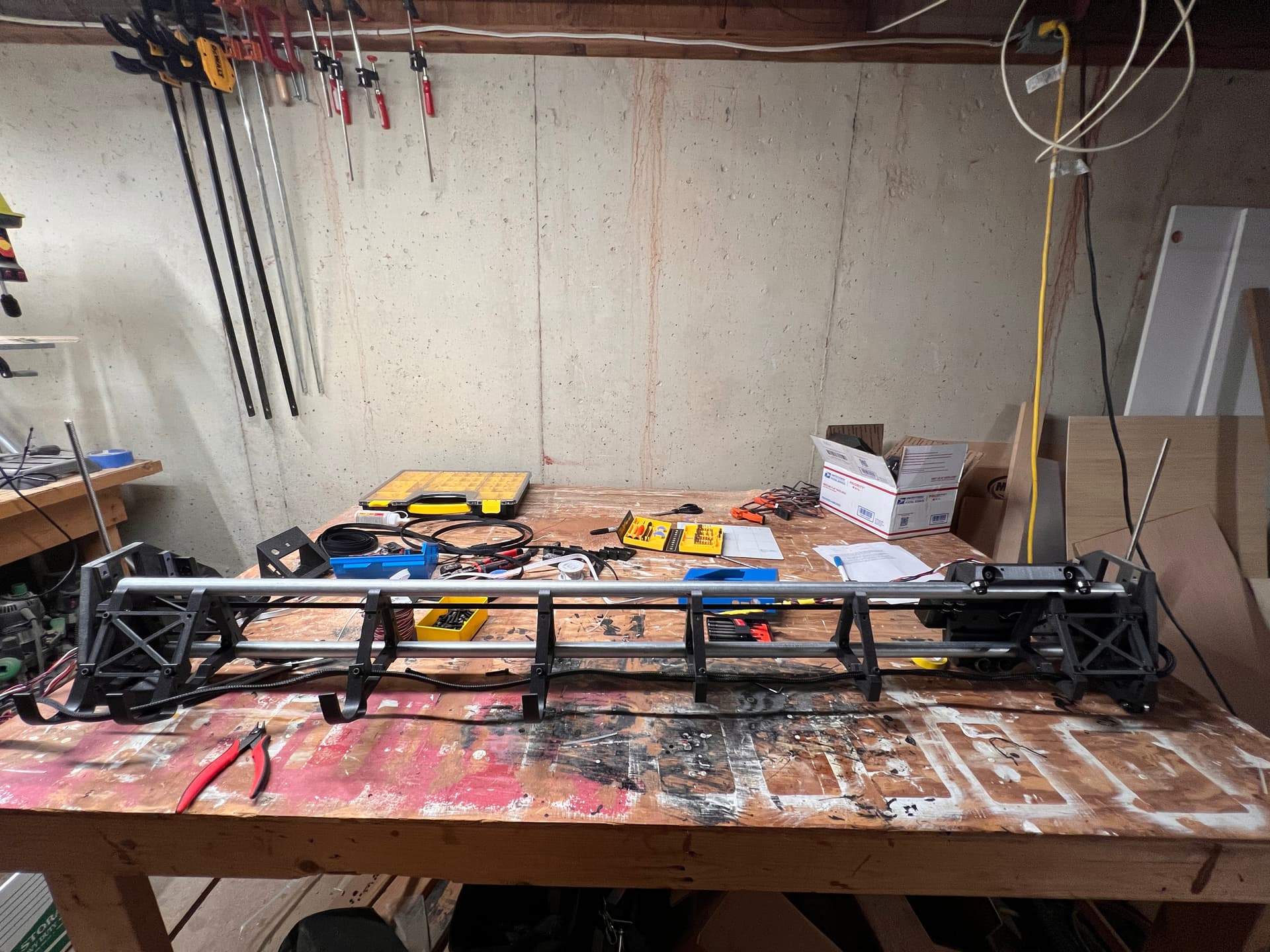
Like many, this is my first CNC build. First started research last winter and designed a table using the LR2 calculator. Naturally, shortly after I got around to building that (the LR2 requirements for tubing did aid the procrastination), the LR3 was released. The printing phase went smoothly over the summer. Assembling has also gone well and I’m currently about ready to start wiring.
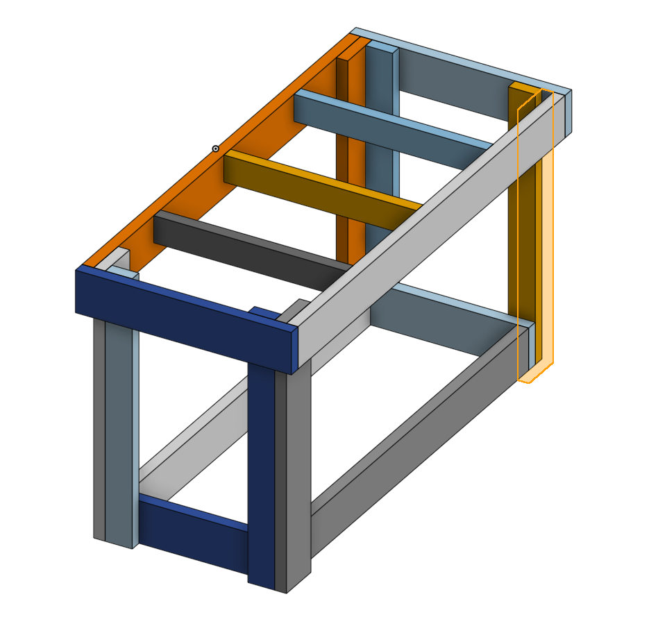
All that being said, I now find myself second guessing my sizing decisions. I have a small shop, thus built my table such that it can split in half. I have 2 of the below (28"x63", which is what the LR2 calculator gave for dimensions for a 48x48 build when the 2 are next to each other)
2x4s, especially the way you’ve laid them out are going to be strong enough to park a small car on. The 4x4 is probably pretty similar, definitely still strong enough for anything.
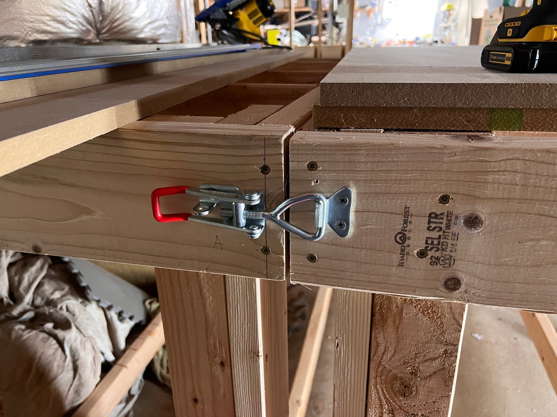
I would put a couple of big bolts between the tables to snug them up together and give you a consistent top height. Just two 5/16" (8mm) is probably good enough. Maybe 2 in the leg section if you have very uneven floors. That will just give your surface a chance at being very consistent across the seem.
I’m pretty happy with the consistent top height I’ve got going. I’ve got latches on both ends of the table snugging it up nice and level. Both sides are also on locking caster wheels so I can move everything around pretty easily.
My current question is actually more because I’m new to CNC/Lowrider. Is the 4x4 aspect ratio going to be problematic? for instance I know I need to cut braces soon, is the fact that my sides are equal at 4’ setting me up for trouble?
The sides being unequal is fine. You do need to cut the braces, and they are larger than 4’ for a 4’ wide LR. But it is about an extra foot. You should be able to fit it in on the diagonal. You can try to play with it in CAM before you commit, but I think it should be fine.
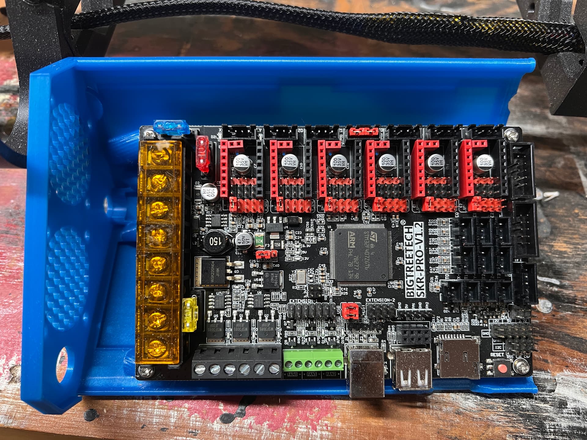
Ended up going 2’x4’ for now. I’ve saved off the 4’ tubes for future upgrading. Got it all wired up (was a little confusing figuring out where everything went based on the pictures. Especially got tripped up not knowing to wire up both the board and motor inputs).
Flashed the board no problem. The TFT had some errors about the config.ini (unknown keys) but seemed to flash ok. After setting the baud rate to 250k to fix the no printer connected error I’m able to get the motors to spin. It reports a “M82” Unknown error however, is that something I need to worry over?
More progress. I’ve got the Y belts installed and XY moving properly. Hitting a problem with Z though.
I flashed it with the brand new firmware released a week ago before trying today’s experiments. When I tell it to move Z (in any increment) it just turns on the motors and keeps going up and won’t stop. I’ve got the endstops plugged in (does orientation on these matter?), but it just goes and goes even when i tell it Z+.1
I get the m82 unknown error every time I turn the machine on. Doesn’t seem to be an issue- I’ve done a couple dozen projects over the past 2 months and all have been great
I wouldn’t mind knowing exactly what it is though, for science, but think it’s something to do with Extruder code
Picking this back up again after a long hiatus. Current state is that it doesn’t seem to be recognizing the limit switches, but trying to keep moving.
I’m trying to get it squared. I did a 100mm square, which measured very accurate along the X and Y axis. When I measure the diagonals for square I get 140.6mm and 142.4mm. Is that close enough to proceed? If not, how do I tweak it to get better?
Just starting mine but have had 3-4 other machines. Figure out which way the skew is and move the end stop trigger to compensate. maybe .9mm or so.
From the Assembly Instructions:
If you are over 1mm in difference you can use the terminal on your SKR Pro or a USB connection and repetier host to add a homing offset. “M666 Y0.5” will move your Y1 stepper 0.5mm away from the stop block after it homes. “M666 Y-0.5” will move your Y2 stepper away instead. You want to move the longer dimension side away from the block. A good first guess is the difference in your measurements (or you can use a trig calculator and add a bit because your end stops are further away than the dots). Now Use “M500” to save it to the EEPROM. Re-home X and Y and test it again.
I use a different controller on my machines so it is a little different. One is software and one is hardware. I personaly prefer the hardware approach.
Less than 2mm is great for a raw build. Easy to compensate for with the instructions Mike just posted. You will easy get that under 0.5mm or the best you can measure.