Hi guys,
Please forgive me if it seems like I’m banging on, but today I tried to print a simple router bit holder (holes, and a pocket). I cut it five times, completely mutilating the quarter sheet of 18mm plywood.
On every occasion, the same error was evident. All starts off well, but as the cut progresses, the near-side Y-axis (where the router is) “drops”. The far (lighter side) is almost 10mm higher than the heavier side. So much so, that instead of lifting 5mm out of the material to move to the next hole, the router actually just cuts a groove.
What I am going to try:
Rewire the Z-steppers from scratch. There may well be an issue with wiring.
If this doesn’t resolve the issue, then I’m considering replacing the Z-steppers with low current Nema23’s (1.8A). Am I correct in assuming these could replace the Nema17’s
You will have to modify the plate cut outs if you want to fit Nema23’s…they are bigger than the Nema17’s
There must be hundreds of LR2 users out there that get by perfectly well using the standard Nema17’s…there is a reason you are not one of them. The problem has to be either lack of power from the motors or too much friction in the drive mechanism.
ensure you are wiring your motors in series…not parallel. here is an instructables showing a way of doing it.
Then ensure you have set Vref correctly for your driver modules
NEMA17 vs. NEMA23 is just the size of the spacing. You can get some pretty freaking strong nema17s. The torque is what to look for, not the size of the face.
Heh?..Nema 17’s are 43mm square and Nema 23’s are 56.4mm square and as the hole in the side frames of the LR2 are ~53mm wide the Nema 23’s wont fit. Neither will a Nema 23’s fit the printed holders so you will have to re-design them in all 3 axis’…might as well start again from scratch.
Hi,
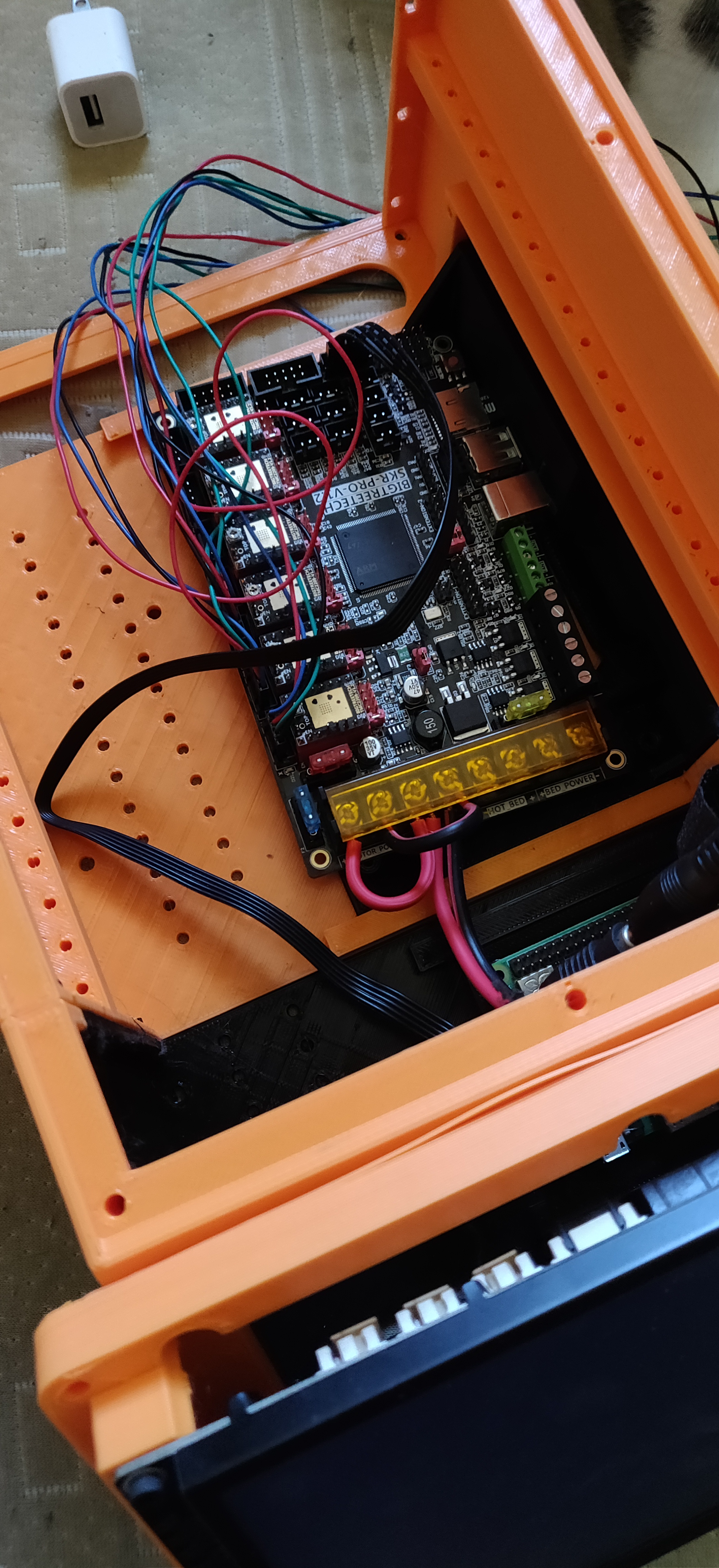
My final attempt at sorting out this stepper issue is going to be to rewire the motors from scratch. Fortunately, my SKR Pro 1.2 kit has finally arrived from Ryan, but I forgot to order the series wiring kit, so will be building my own. So I’m taking the opportunity to swap this in, since it requires wiring anyway. I’ve got a box of Dupont connectors, a zillion little Dupont pins, the crimping tool and a couple of metres of rainbow ribbon from which I can tear 4 wires for each stepper.
If I understand things correctly, each stepper plugs directly into the board in the X, Y, Z and E0 & E1 sockets, and since the firmware has already been configured by Ryan, I should be good to go?.
Some newbie questions:
(1) Each of the two coils in the stepper motor has two wires attached to it. So I should be able to identify them by using a multimeter. Is this correct? Mike’s link to the series wiring diagram above will allow me to connect the correct wires going back to the board, I hope.
(2) How do I power the SKR Pro 1.2? Can I use the Rambo power supply? I’m guessing so, but I would need to daisy-chain the power and motors together, like on the Rambo board.
If you are going to use E0 and/or E1 then you do not need to do any wiring changes as each stepper motor plugs into its own stepper driver, you only need to wire two motors in series if you are going to plug them both into a single stepper driver.
Yes, the four wires going to each motor are two pairs, each pair will have around 2ohms between them. You can use a meter to find the pairs or you can connect a random two wires together and manually spin the motor shaft, if the two random wires are a pair the motor will not spin as freely as when all the wires are disconnected.
I don’t have a SKR Pro 1.2 board but it looks to me like you can use a single PSU and just jumper between the three power inputs as required. I assume you didn’t mean daisy chaining the motors together…just the power inputs
Hi, and thank you for your replies. I have jumpered the power, and it works as advertised. I downloaded the LR Dual image, flashed it and all is well. My remaining issue is that I can’t get the physical plug connections right - my fingers are too big, and my eyesight too buggered. I have the wire, the Dupont plugs and pins, and the crimping tool. But it’s all just too small. But I’ll give it another go today.
For the dual endstops. The wiring is just straight through. I am guessing you are somewhere that is hard to get wires from Ryan but he sells the dual endstop wiring kits. There are also stepper wires and extensions available elsewhere.
Hi Jeff/Barry,
Yes, I’m in Aussie. It’s not that it’s difficult to get stuff here from Ryan (although US Mail is just as bad as freight from China, but costs about six times as much!) On average, stuff takes a full four weeks to get here. And the reason I didn’t have the wiring kit was that I simply forgot to order it. When I went to order it separately, freight was going to cost - wait for it - $83 USD! That is ridiculous. So I decided to make my own cables.
Talking of cables:
(1) Downloaded the LR Dual image, and flashed it to the SKR Pro 1.2
(2) Cabled the 2nd Z-stepper - no issues - both go up and down as expected. Yay!
(2) Cabled the 2nd X-axis stepper - and it doesn’t move. I checked the wiring, identifying the two cables which are on the same coil, by placing my multimeter on wires #1 and #2, and then on #3 and #4 - a nice little tone indicating they are on the same circuit. (Please excuse my non-professional terminology, but this is new new new to me.
I thought that perhaps my wiring might be suspect, so I connected a store-bought stepper directly to the motherboard. Also no movement of this 2nd X-axis stepper when I nudge the router along the left/right (X) axis.
Just to be clear:
My X-axis is the long axis, causing movement on the wheels, the Y-axis is the short one causing the router to move back and forth along the rails.
However, I am confused by this sentence on the V1 web site:
“If the firmware is set for EXTRUDERS=0 then E0 becomes X1 and E1 becomes Y2. (or LR would be E0=Y2 E1=Z2)”
E0 = Y2? There is only one Y-stepper? Is this a typo?
Likewise, the web site says:
“For EXTRUDERS=1 E0 is used and then E1 becomes X1 and E2 become Y2. (or LR would be E1=Y2 and E2=Z2)”
Same thing. A single Y-stepper only. Is this my issue? From what I can see, I have EXTRUDERS=0, so am I correct assuming E0=X2 E1=Z2 but I suspect this is where I’ve screwed up.
The parts and instructions all assume the wheeled axis is Y and the long tube axis is X. So the firmware also follows that convention. Sorry if I confused you on that.
Dual endstops on the LR didn’t used to have a preconfigured option. So we have had to make some choices. The firmware homes Z up, and has G38 for probing down.
Hi Jeff,
The wheeled axis is Y? How weird. I’ve certainly never seen that arrangement on any graph before, where the X-axis is always the horizontal one, and the Y-axis is vertical.
Anyway - it feels strange to configure my setup this way, so how do I change this in the firmware?
Second question: The firmware file I downloaded and flashed was v505 - which lines do I need to update?
It’s all a matter of perspective. If you stand at the end, the X axis is to the right, the Y is away from you. If you stand on the side, it looks wrong.
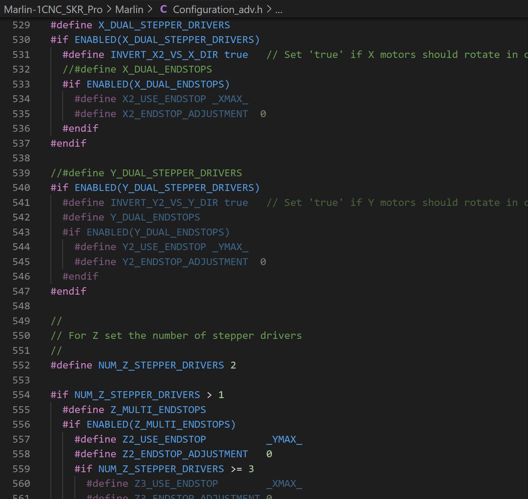
The changes need to be in configuration_adv.h. You need to disable the dual Y, enable the dual X, and change the Z2 endstop to the Ymax (in the same section).
You could also just wire the two X steppers in series (do you still have your old wires?).
Hi again,
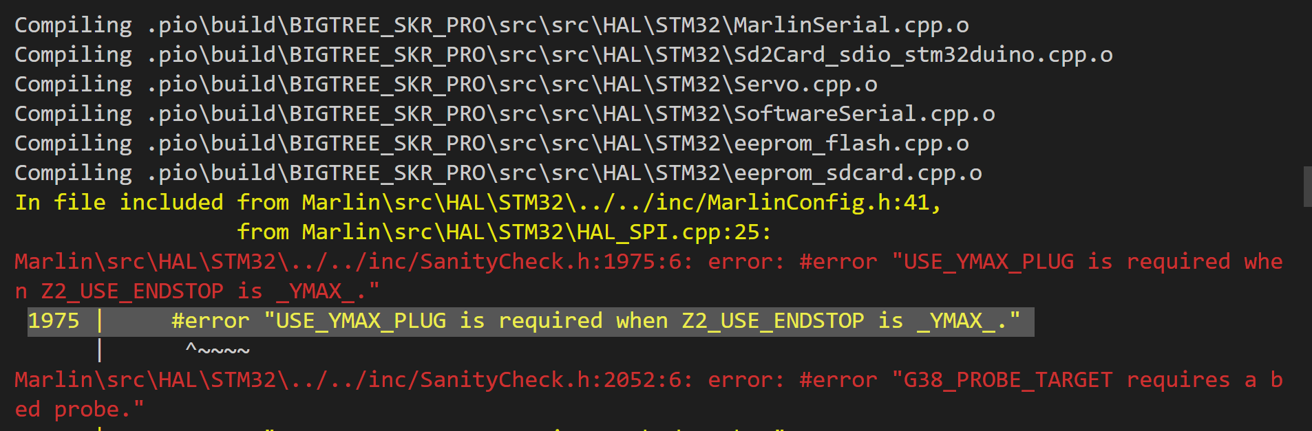
I made the changes you suggested, and tried to recompile. However, I get the following error:
1975 | #error “USE_YMAX_PLUG is required when Z2_USE_ENDSTOP is YMAX.”
I’ve tried to search for this setting but can’t find it.