Low & Slow. This is gonna be a while

Sled done. Realized that there isn’t much that I can do when I don’t have the steel here. Those are the old X rails from my first ZenXY table, which I could use to set up the router sled, but setting up the YZ stuff pretty much needs the Z rails at least, and the X rails would be nice to have. That will need to wait for next week when I can buy stuff from work.

I’m going to make the table frame from 2x2 square tube, because I can get it cheaper than 2x4 lumber O.o

Should have snapped a picture of the box as released by customs…

3 Likes

Worlds smallest low rider.

1 Like

They have an invoice with every part and price broken out, they made up their own value?

I have heard of people having to show them the website or credit card statement to verify the prices. This is why I have never fudged any import docs. I hope this doesn’t flag my boxes in general.

So sorry you had to go through all that.

Odd times we live in, I need to grab some metal myself before that starts getting nuts.

I have no idea what they did. The paperwork is unreadable. I suspect that there may be a flat fee added as well. (They’re supposed to either do the flat $10 fee, OR charge tax, but not both.) and they’re pulling numbers out of their collective behinds.

I think that whoever was trying to put that box back together may never want to see another one in their lifetime. It was pretty bad.

1 Like

Put a few more bolts in. On both plates, I put the first piece on the wrong side first. Kept thinking because all the pieces go on from the same side, the bolts do too, and… Bzzzzzt!

They’re correct now of course.

2 Likes

I was looking at end stop solutions, and decided that I wasn’t completely happy with what I found.

I decided to whip up something quick in Tinkercad.


The switch holder takes the lower roller and subtracts it, so the mating surface exactly matches the surface of the V1 part. On the .STL you can still see the “J” though I flattened it out, so it doesn’t print.

I need to revise it a bit to reduce the distance for the plunger holder, I think about 5mm looks perfect. I could have left it the same for both sides, but made a mirrored part so both switches will be on the same side of the machine.

The plunger is a 1" #6-32 screw with a cap. This makes it adjustable to get the offsets as close as possible. I could of course use a shorter screw, but the same as existing ones in the build is also good. A 3/4" #8 wood screw will expand a plug in the tube to hold it securely.

Edit: Tinkercad project

2 Likes

I kept mine simple and just clamped the switch to the Z-tube. The switch hits against one of the z roller assemblies, so there is nothing additional to print/attach to the y-plate.


A couple of minor adjustments.

I added a hole for a zip tie to keep strain from the switch terminals. Also fixed the distance for the plunger.

Yeah, I saw that, but wanted easier adjustability. I know that the switch offsets can be set in firmware but the ease of turning a screw appeals to me.


These are the parts. Fitting the shape to the roller keeps things fairly rigid, even with just the one bolt. I found that there was more than enough thread on the bolt to hold the extra piece.

I also finally managed to get the Primo style belt holders printed last night. Just have to finally decide on the project dimensions and order the steel.

1 Like

Yes, no firmware adjustments needed - I just slid the clamp up or down until the switch is triggered (they were only a couple mm off from each other so didn’t have to move much).

Z Endstop for LowRider 2 – Thingiverse

Just put the pieces for this up on Thingiverse, so if anyone likes it, there it is.

I plan to do something for X and Y endstops as well, hopefully also making parts where no extra holes are needed in things, and a minimum of travel is lost.

Going a little sideways.

I got started on designing an X and Y endstop, and started looking at adding a laser. Not quite sure how that transitioned, but… Here I am.

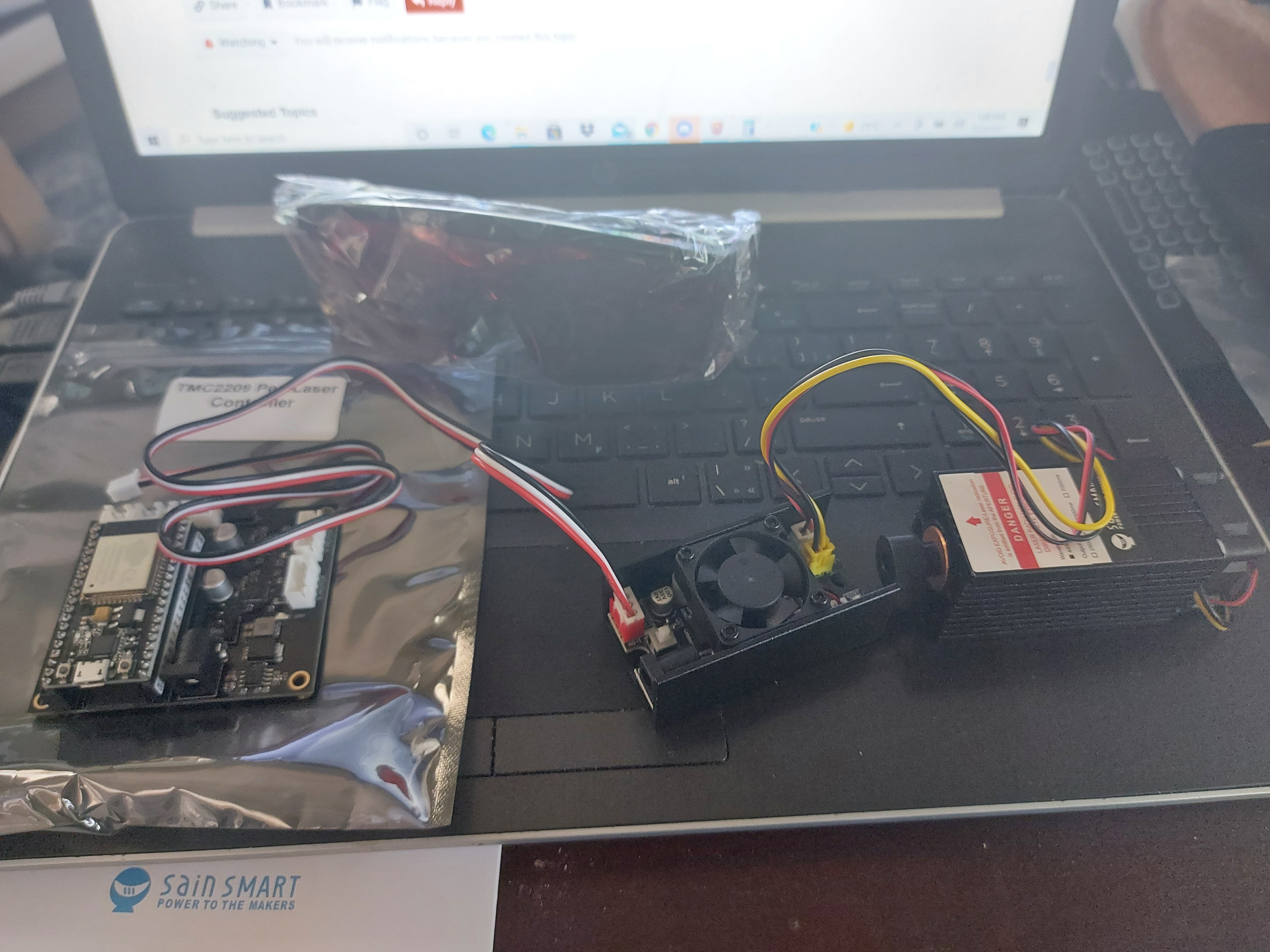
So assuming that I’ll be using the SKR Pro 1.2, I’m a little foggy on what I can use as a PWM output for controlling the laser. Looks like the unit that I chose uses a 5V trigger signal, PWM for laser power. This makes the math easy, but the actual control is a little harder than direct controlling the laser with Vin voltage (ie: 12V.) It does, however allow me to use 24V power, which is nice… Well, except that the laser power supply itself wants 12V. Well, I do have a 24V - 12V converter, up to 4A, which is good for 48W, and the laser takes a max of 2A/24W as per spec, so no problems there.

My plan will be to use aircraft panel connectors for the laser. Looks like 4 wire connection from control to laser, and 1 pair is just for the heat sink fan. Should be easy enough to do as a module that I can just plunk onto the carriage.

So the next question is… Where can I get a 5V PWM pin on the SKR Pro 1.2 so that I can control the laser form Marlin?

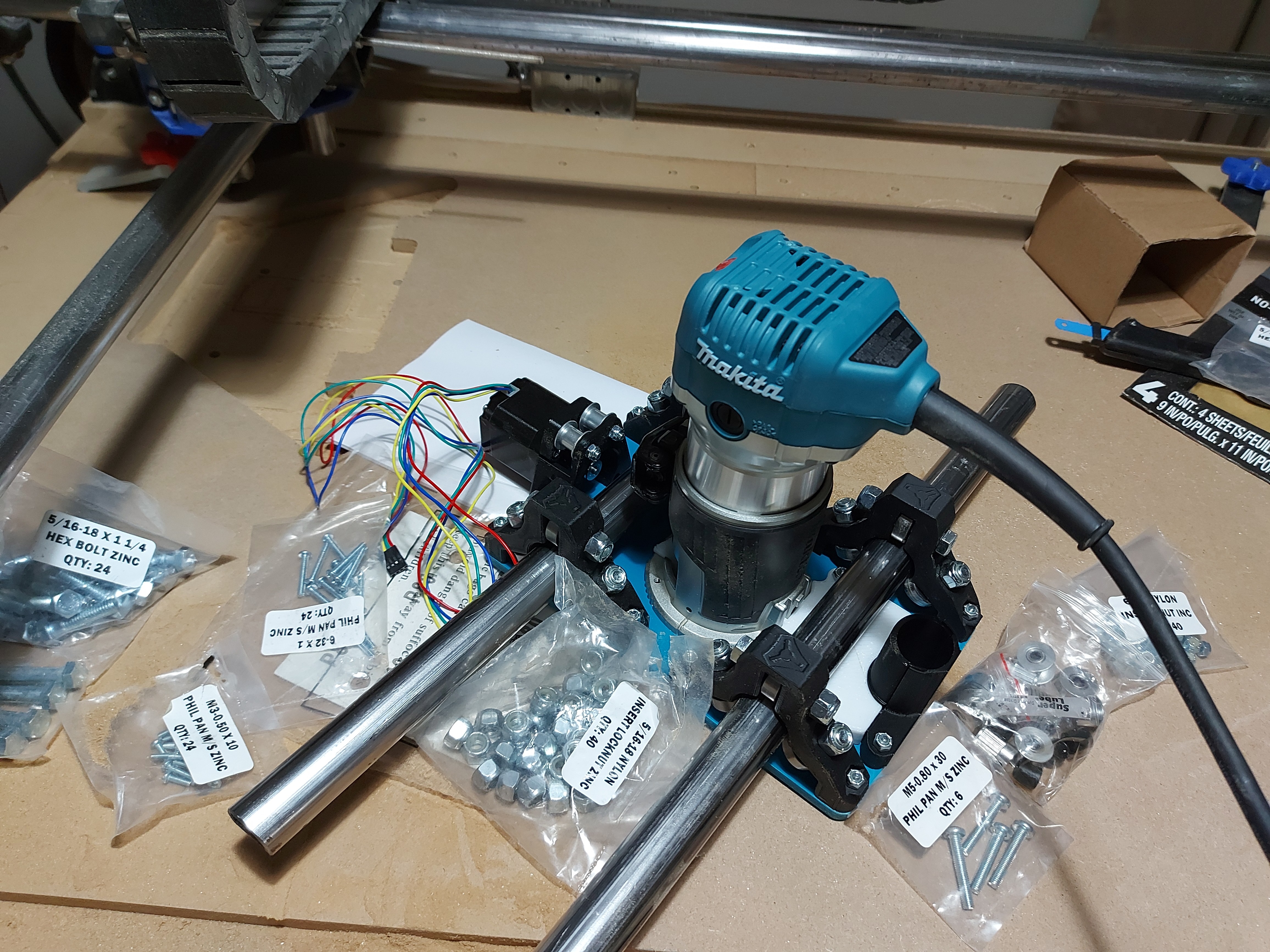
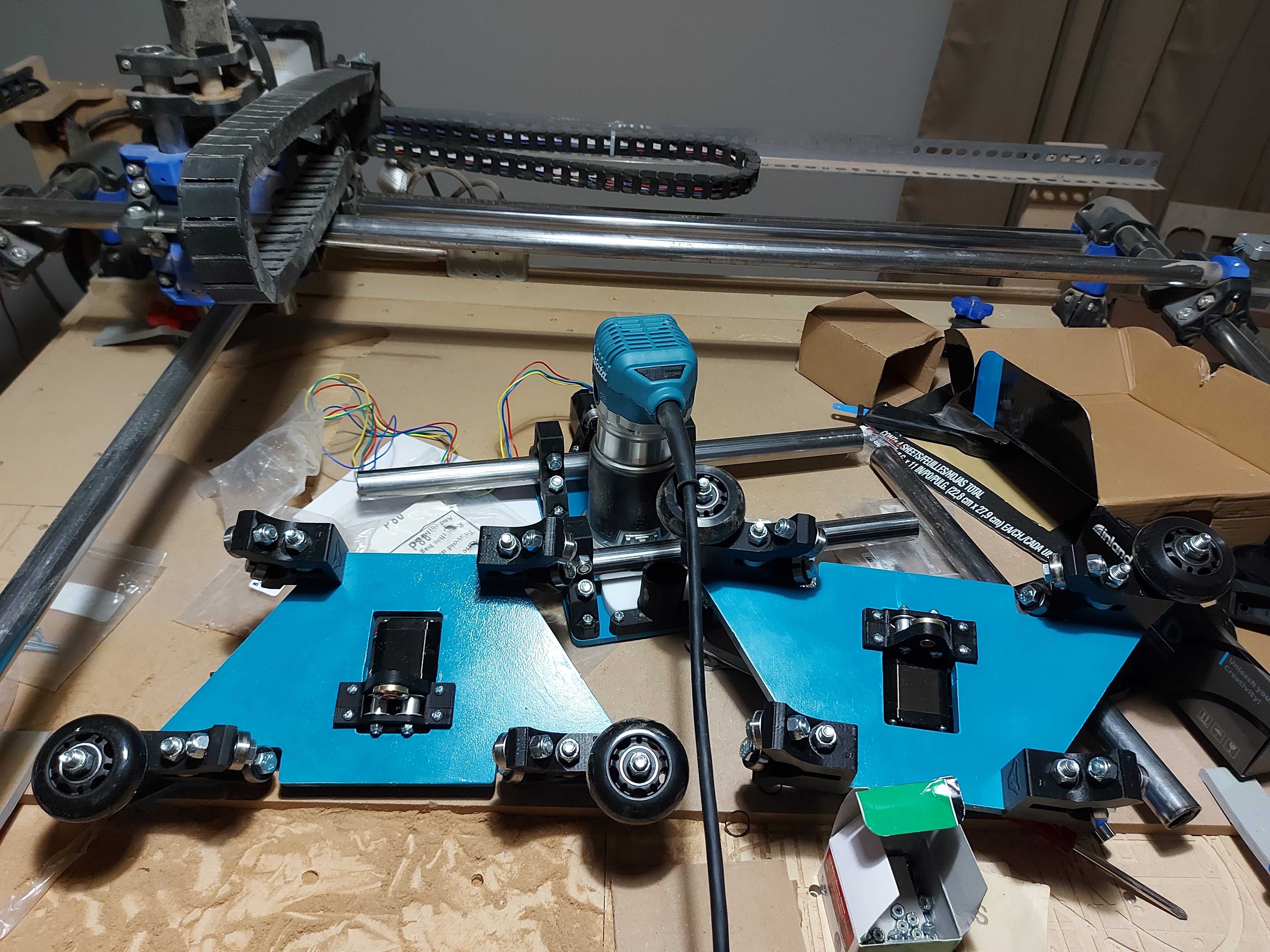
I think that I’ll set the machine up so that I can use either the spindle (Makita RT0701C) or the laser. Make a laser carriage that replaces the router in the clamp, and this time, don’t put the power cord through the drag chain, so it’s not a major pain to remove the tool. I did that on the Primo, which works great for keeping the power cord out of the way. Not so great for pulling the router out and substituting a different tool.

Also looking at various solutions for air assist. I kind of wonder if the vacuum shoe might just manage the job. The vacuum is a little loud though, so I’ll probably play with something that pushes air. I have an aquarium pump good for about 2.5L/min. It’s not much, but enough? Dunno.

I’ve been reading this thread on setting up a laser. Not sure if there’s a better reference. Much of this seems to look like the firmware “will just do it” in stock form, which would be awesome. Maybe I’m just overthinking things. Edit: Duh. My linked thread answers the first question at least twice, I guess I ignored it because it says 3.3V

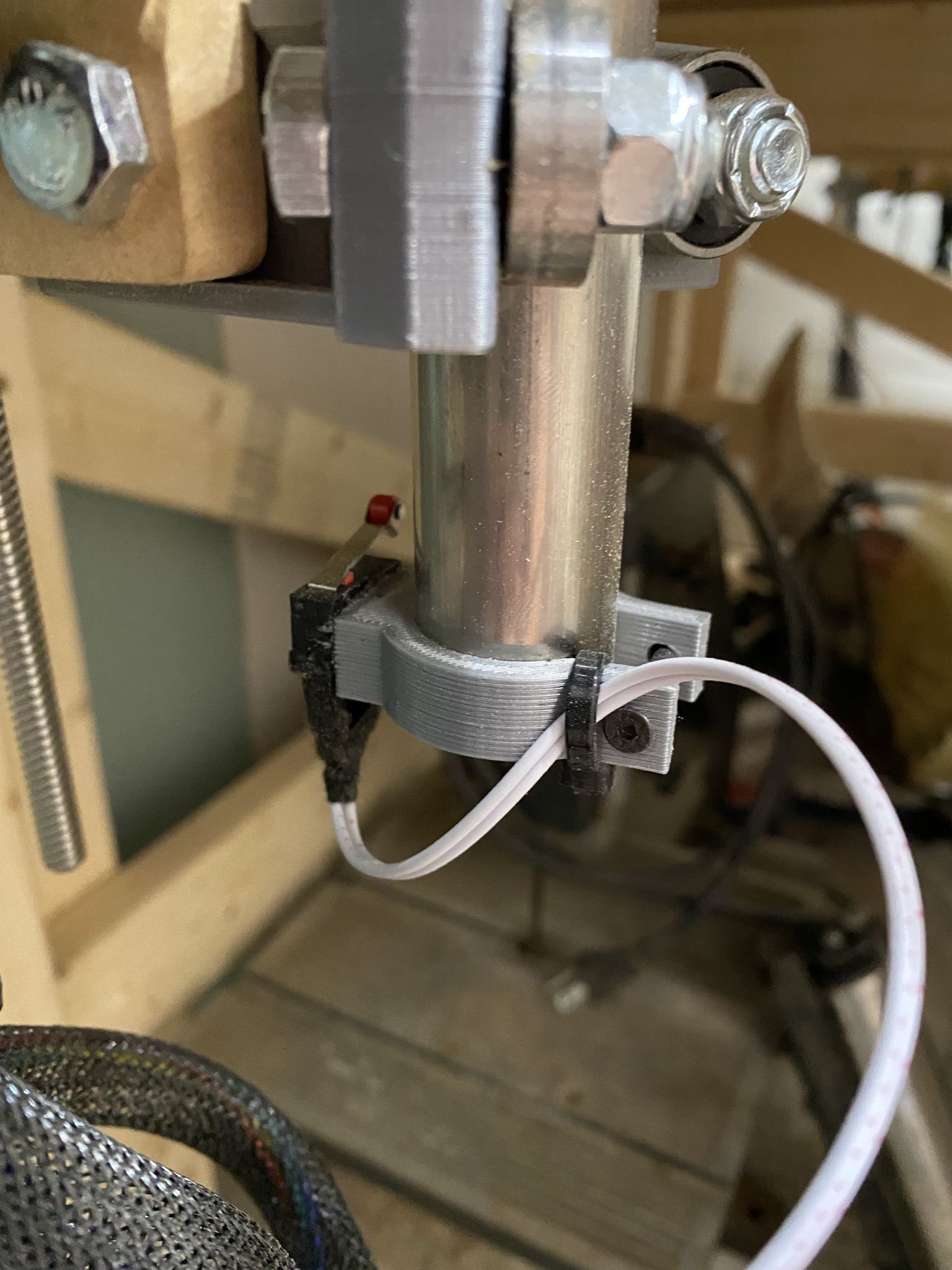
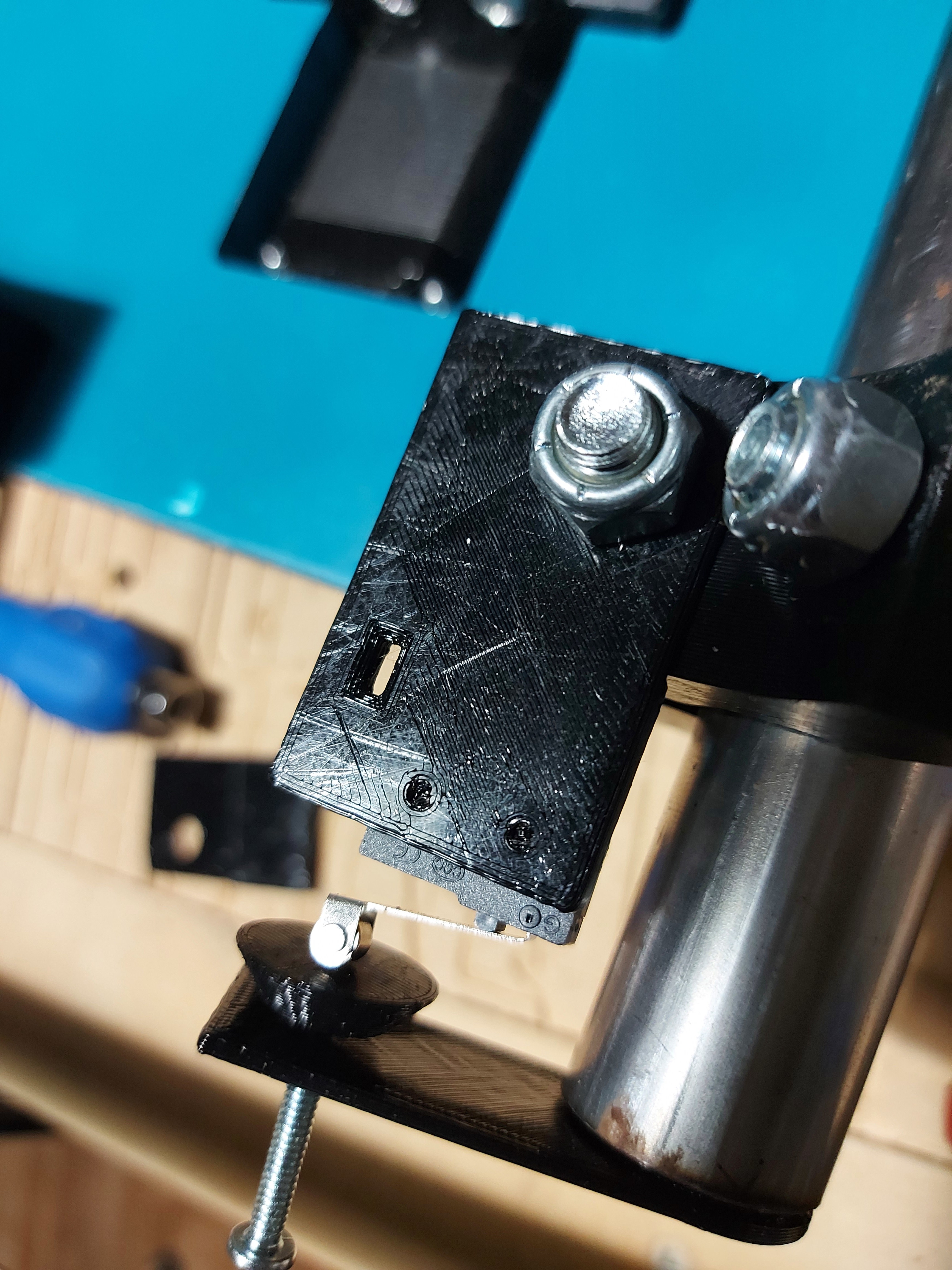
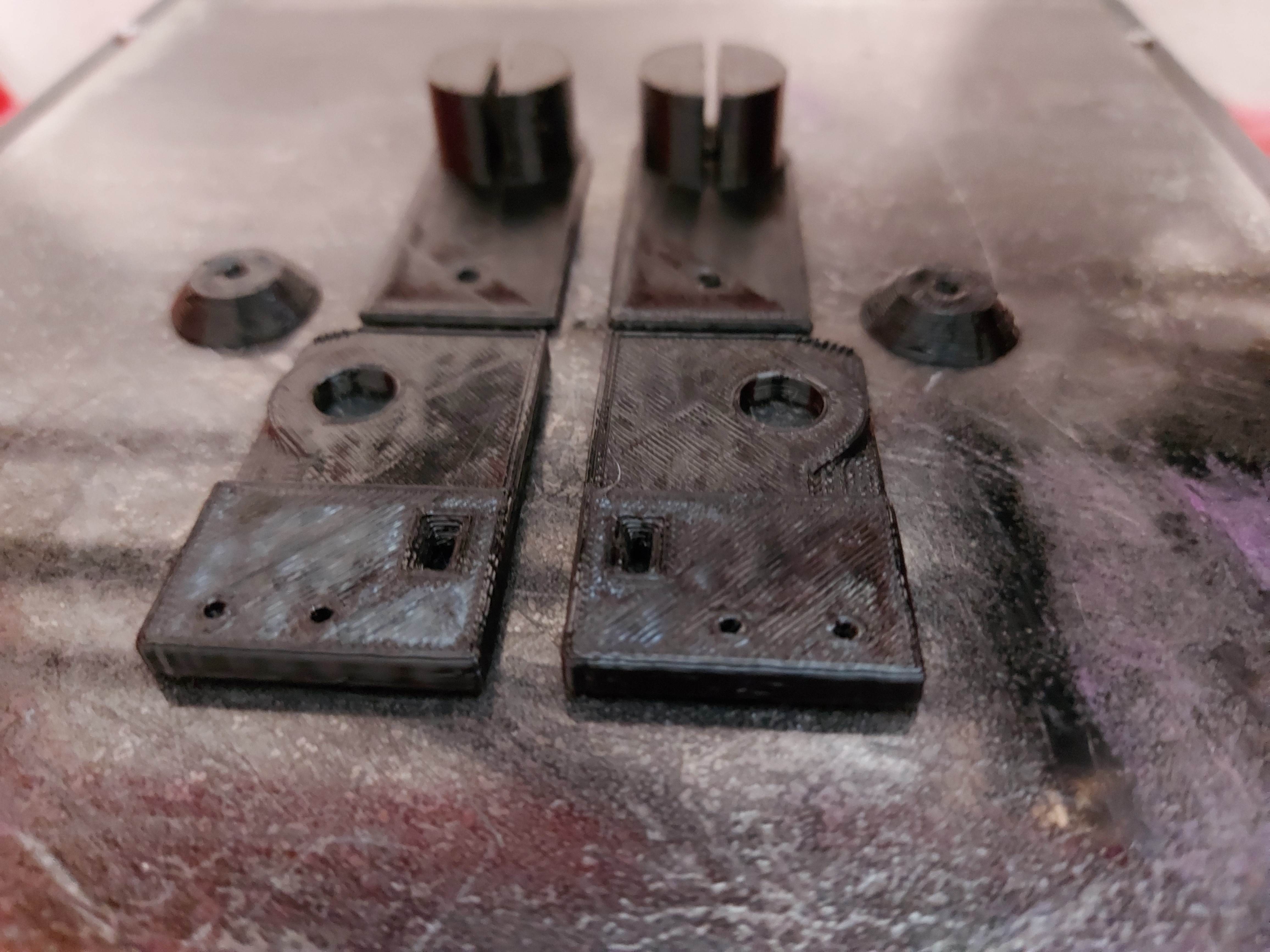
Anyway, I have what looks like it will be a good laser mount for the Makita carriage. If the aquarium pump will be adequate for air assist, (I’m sure better than nothing) then I might look at having it mounted alongside the router, but I’m worried about dust contamination so removeable makes more sense to me.

I was thinking that I would set the laser focus at a fixed distance, and set up a #6 screw as a contact, for the alligator clip on the touch probe, and use a known size block with the touchplate to set Z=0 as the laser’s focal point.

This is my pennance for abandoning Marlin in the 1.x days (Except for really simple stuff, or where pre-built configurations exist) and going to RepRapFirmware. I’m sure that I could do all this with a Duet, but don’t just know how to do it with the SKR Pro.

1 Like

This will all be fine. You can engrave plenty without the air assist. I would start with a “1.0” and then get all your focusing, pwm, laser mode, mount, etc. learning out of the way. Then figure out “2.0” with the air assist and better wire mgmt.

1 Like

Yeah, I’m kind of the type to over obsess about everything until I get more things figured out than will ever actually go wrong.

And if I get a “1.0” figured out and it works… “2.0” isn’t likely to happen, so I try to get at least the options set up for things that I’m going to want in future. Sometimes this comes around and bites me. For example, my 3D printer was working, and so I left it with bad wire management for a couple of years, just using it as it was with a piece of string holding the wires up… Then one day while printing, the string let go, and the hotend ran over the wiring harness, and shorted 24V to a bunch of stuff that didn’t like it very much. So… I have a Duet Wifi that’s had the main processor and a motor driver replaced… And now I have a proper drag chain over the wiring harness. My DIY projector still has the display controller mainboard held up with a duct tape and bubble wrap sling. I think I completed that in 2007? (One of the things that I always wanted to do with a CNC was to build a proper case for that, but it’s buried under other stuff right now. I am planning to do a nice case for it still though, once the price of lumber gets less unreasonable.) As it happens, some of the parts for that I designed, I still can’t do on my Primo.

Anyway, I know how I am with stuff like that, so I try to adjust. Far too many “quick 'n dirty” prototypes have been left in service far past their initial estimated lifespan, so I try to make the prototypes at least a little better, or worse, where they absolutely need to be updated ASAP. Problem with the “worse” option is that sometimes it doesn’t work, and is too much work to fix, because I didn’t leave the options open.

And of course, I’ve got my CoreXY design to think of which looks more and more like it’s going to be a laser controller rather than a 3D printer…

Too many directions to go in all at once…


The Amazon fairy arrived… and something unexpected…

Back in early June, I ordered one of Bart Dring’s laser controllers, with the intent to swap it into the Zen table I built. Well, at the end of June, the tracking number didn’t appear to be anywhere, so I shot him a message asking if that was normal. I gather that it wasn’t, because he dropped another in the mail, which arrived promptly.

Well, the first one arrived the other day…

So, I’m probably going to make a dedicated laser engraver, provided that I can get the firmware sussed for the ESP32 to do the PWM. This can be allowed to move much faster than the LowRider, though I probably can’t really etch at much faster moving speeds with this.

So, the LR project probably won’t have much to do with the laser after this.

1 Like

Found a cantilevered CoreXY laser design on Thingiverse that almost looks lie the designer was rummaging through my parts pile. Everything, including the oddball MGN15H linear rail is already there. The only “setback” is that my MGN15H rail is 500mm long, instead of the specified 400mm.

Well, until it was time to print the parts. The base depends heavily on a usable 220mm by 220mm print surface, and I can only use about 200mm in X. Also, there are 3 parts that really need supports. I lucked out on one, and it printed without supports acceptably. Another I was able to make minor edits so that it didn’t need supports, and the third… I’m still working on.

I print at fairly high temp, and don’t have a part cooling fan on my main printer. It works well for me for parts I design, since I tend to design parts that don’t need support. Anyway, I hacked the base apart to only get the parts I need. I’ll cut most of the base from plywood and fasten it together. This is where it ties in to the actual subject of the thread, it may end up getting cut on the LR2.

I’m stuck waiting on steel. I’ve been to busy at work to ask about getting some steel. so it’s my own fault. The price of a 2X4 is down to about half what it was, making a lumber table … still more expensive (for me) than steel, assuming that my welder still works. It’s been sitting in the garage a long time now. I home my welding wire is still OK, and that my argon tank is still full. I’m trying to think if I have a large enough flat surface to weld a table frame together and have some reasonable hope that it in turn will be nice and flat.

It’s been a drainer of a day, and I’m rambling.

That looks like a great design. I don’t like the steel belts. I also wonder if the gantry rail should have some kind of 2020 support. But otherwise, I really like it.

That is tempting …

I didn’t notice the base frame was 3D printed. We should remake it with 10mm belts (because moar! and 10mm idlers) with plywood base.

For as short as that rail is, it’s not going to need support.

1 Like

Me neither, but that’s an easy substitution, and I have tons of 6mm belt left over from my first Zen table that I disassembled, even after building the MP3DP.

My frame base won’t be entirely 3D printed, and I’m going to leave the MGN15 rail to span the center portion. I chopped out the portion of it that I need, and will mill the rest.

Hopefully. It looks like a nice lightweight design. The tolerances are super tight. I needed to file my 3D prints a touch to get things to fit, and like I said, my printer sucks with supports. (The MP3DP just isn’t dialled in tight enough to make it possible, but I might need to re-do that one piece with it anyway because I may need the print cooling fan.)

I have a translucent red filament that I’ve been printing parts for this in…

Looks pretty cool in the sun!

The MGN12 rail in that photo is longer than the one I will use… but I’m having trouble getting the test fit parts off.

The base parts seem more than sufficient cut down like that., but it’ll need more support when it’s done.

3 Likes

That filament looks like jolly rancher red.

3 Likes

Oh, please. That’s twizzler red. Fight me…