Low & Slow. This is gonna be a while

Thanks in a million :slight_smile:
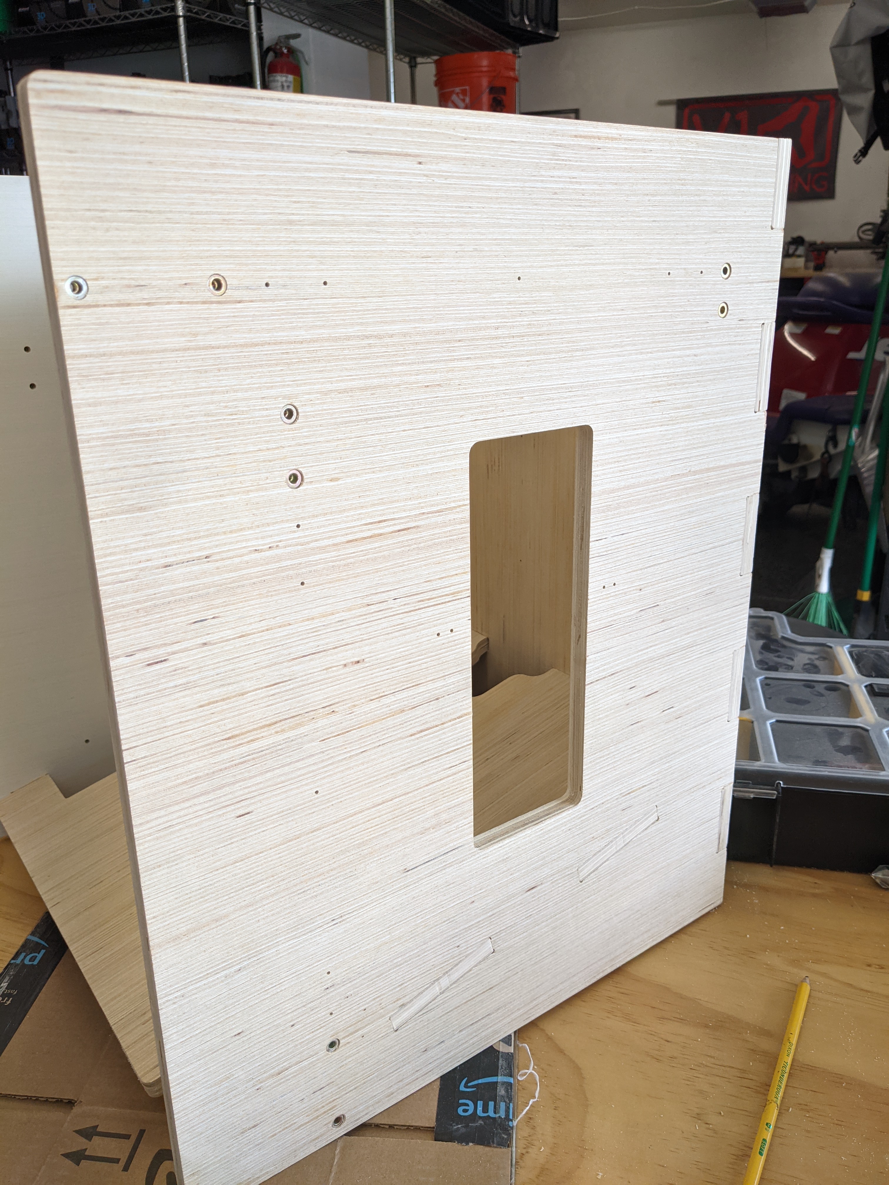
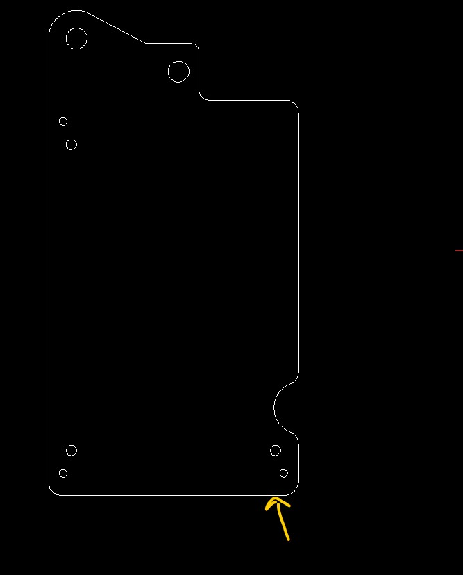
I was just checking out your files when it struck me: why not mount the limit switch directly to the ā€œSKR Pro mountā€ youĀ“ve designed earlier? Sure it will be a large part that on one side will have no other option then to mount the switchā€¦

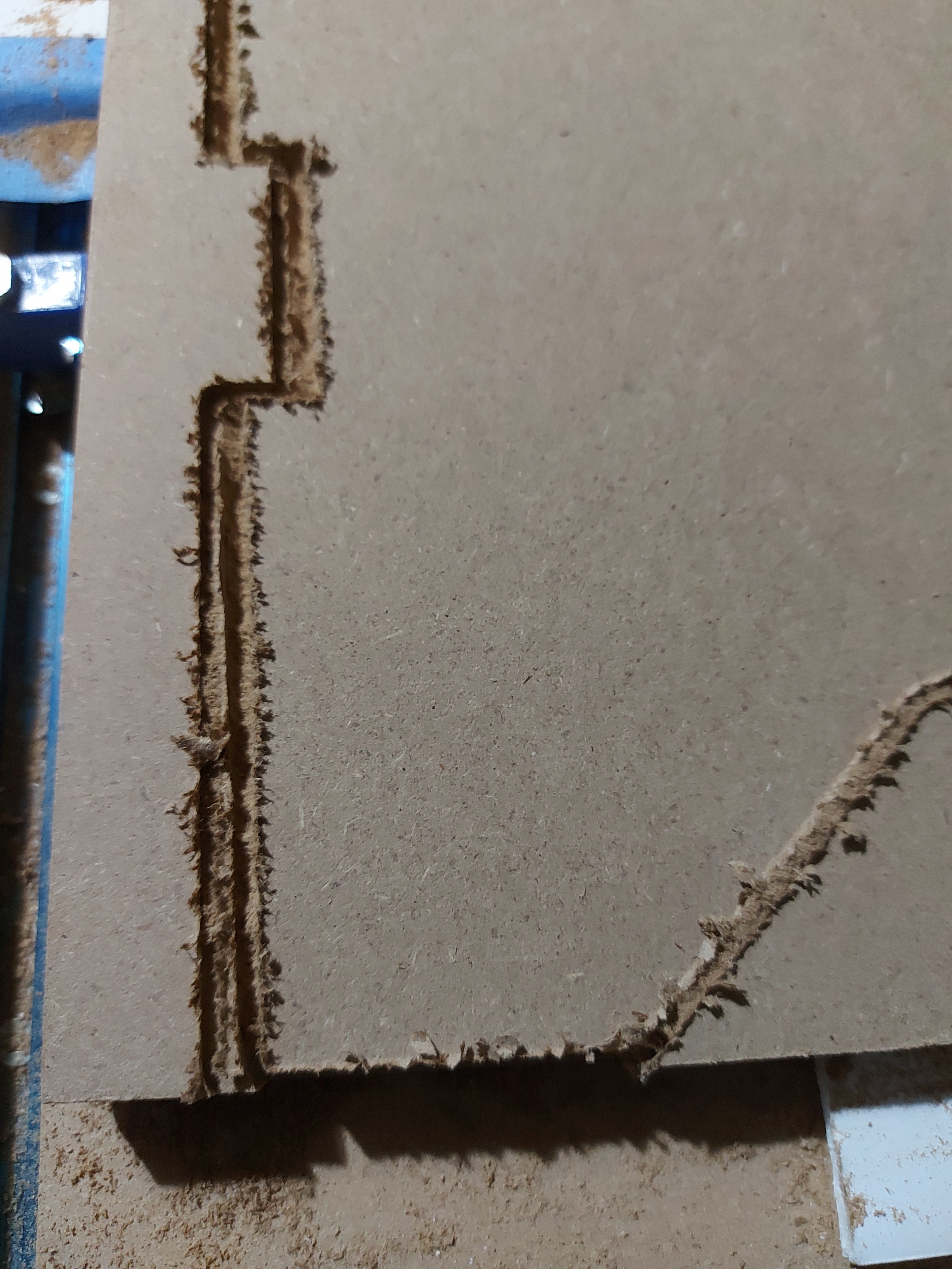
I think it would be just a matter of drilling 2 holes here:

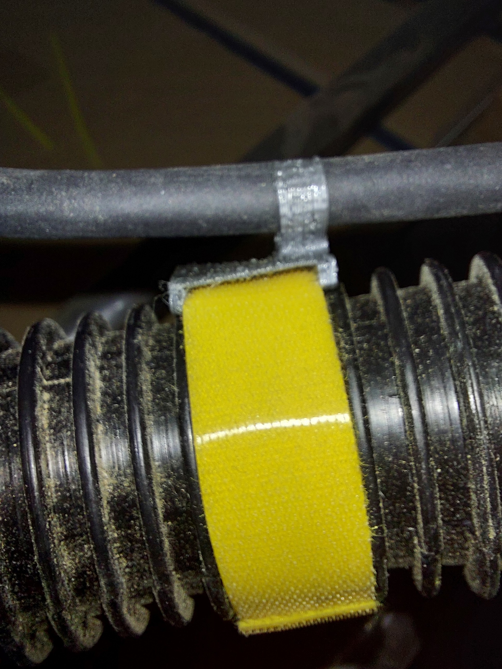
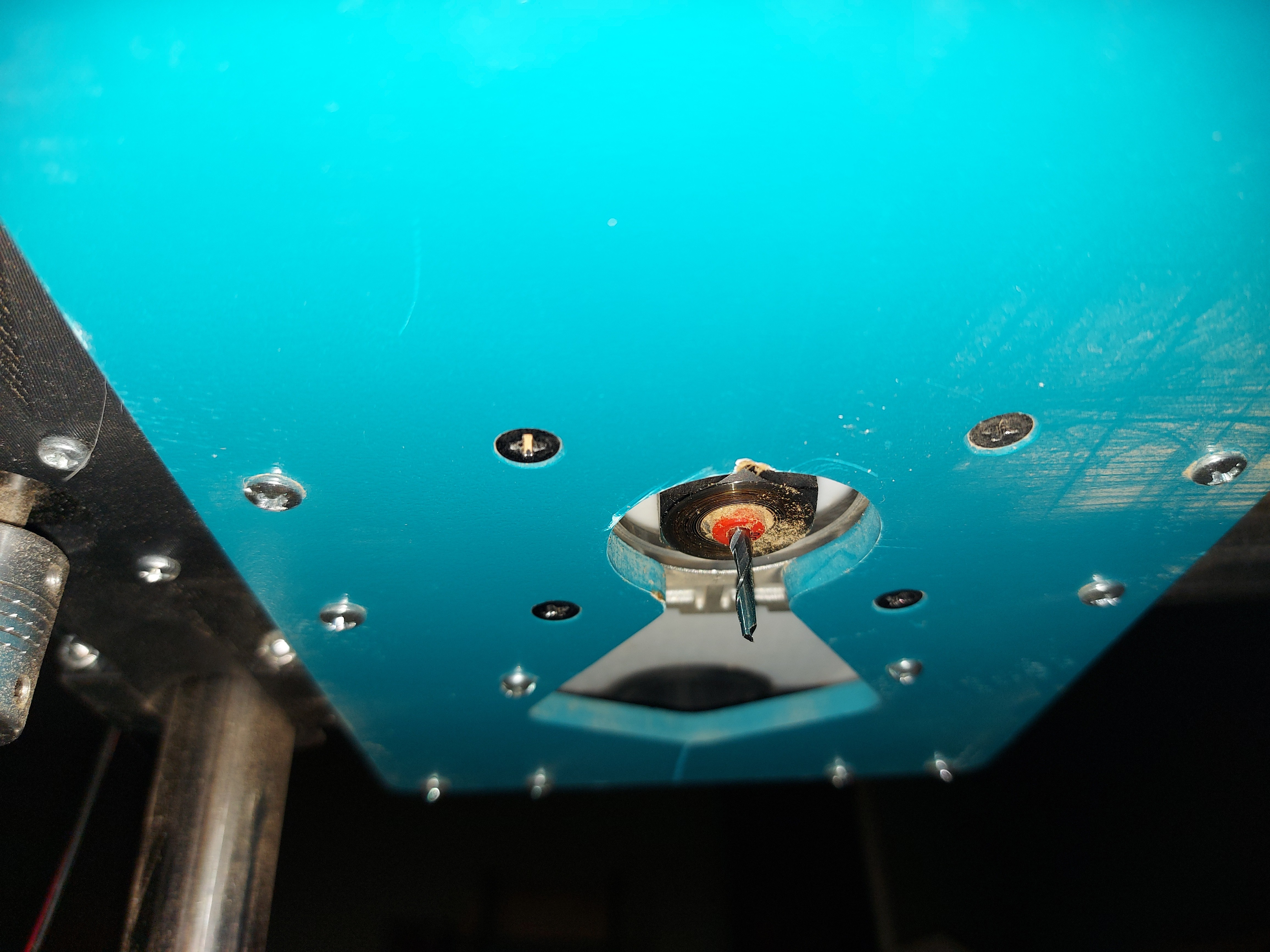
Bummer! I had something similar yesterday when testing with a pen (still not used the machine for something else). On one side the cabling was locked below one of the wheels, so it couldnĀ“t lift that side on the Z axis. Obviously it took me two seconds before realizing this. One side kept going up, the other one stretched the coupler. Still hoping that it hasnĀ“t caused any issues.

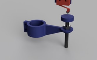
I am far from an engineer, but I think thatĀ“s because the Z end is horizontal instead of vertical. I believe thatĀ“s on itĀ“s weakest point. If you would rotate it, or add something vertical instead of horizontal, it would be stronger.
Schermafbeelding 2021-09-30 092653
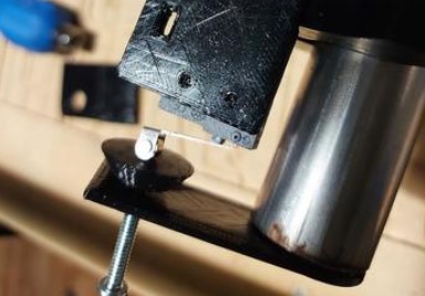
not sure if you understand what I am trying to say. So let me give an example by 4noxx, his endstop is vertical giving more strength for downwards force.
Schermafbeelding 2021-09-30 093058

Because itā€™s about an inch or so further from the tube and about 3 inches lower. This would mean that Iā€™d need a longer Z tube and it would give more leverage against the plunger to move it with small forces resulting in inaccuracy. I also wanted something really close to the tubes (which the edge of the Y plate is not) to mount the Y limit switch. Thereā€™s also the matter that I did not install that board on both sides. It would be fine if I only needed Y and Z limit switches on one side of the machine, but then thereā€™s nowhere to mount them on the opposite side.

It pretty much has to be that orientation. Itā€™s printed plastic, which can be reasonably strong, but to within limits. Iā€™d rather break that piece of plastic than the one holding the bearings, for example if the Z axis were to be lifted without reading the limit switch. As is, the switch holder will be much stronger, and the plunger end will break. Since thatā€™s a really quick fix, itā€™s easy enough to replace. (It took me a half hour to print a replacement part and install it, with 20 minutes of that being print time.)

Your example piece there needs another 3/4" of Z tube (Or loses 3/4" of Z range) and the part holding the plunger is still going to be no stronger than mine.

So I bumped the X motor power up a bit, and cut new Y bump stops. No skipped steps at this point, though it was a small cut, so nothing conclusive there.

Next step is to cut a small tabbed box in order to test the dimensional accuracy of the LR. I am reasonably sure that itā€™s fine, but I do want to test before cutting printer panels.

I am not sure if I agree that the direction of the plunger wouldnā€™t make a difference. As the direction of force and the direction of reinforcement is related.

But I understand that when your tubes arenā€™t long enough, it doesnā€™t matter at all :slight_smile:

It wonā€™t to breaking strength. Thatā€™s determined by the cross sectional area, and whether or not layer lines are involved. Assume no layer lines in both cases, then itā€™s cross sectional area, and thatā€™s smaller for those than mine, because mine is still about 1 1/8" wide. I actually wanted it to flex in the case of overpressure, since that is less likely to break, but with enough forceā€¦ It broke. Probably in that case, almost any reasonable printed part would have, but fortunately, these are very quick to print up a replacement.

Iā€™m having hold-down problems. I tried to cut my printer back plate, and the work moved. The bolts that I have for the T track just arenā€™t quite long enough, so I got some T nuts which will fit in the tracks for 1/4"-20 thread, which is the same as I use in the Primo spoilboard. So Iā€™ll be able to use the same hold-downs for both.

Meanwhile, I just ruined a quarter sheet of 12mm MDF. :angry: :anger: I have re-made my Y endstops. I cut the MDF parts with the machine quite a bit out of square, but fortunately that doesnā€™t matter, so long as itā€™s within its adjustment range, which it is. I might re draft up printed bump stops, but if this works, Iā€™ll leave it alone.

I also got some angle. My drag chain solution seems inadequate, so Iā€™m going to pull the drag chains off. The good news is that now I have a vaccuum hose on the dust shoe, so I can run the wiring next to that, and velcro-tie it together. Iā€™ll re-print cable clips for the router with a tie opening so that I can still easily remove the router. I also want to tweak my pen/drag knife holder.

The dust shoe isnā€™t quite as good as Iā€™d hoped, but itā€™s not bad at all. I could use a more powerful vaccuum and a separator wouldnā€™t be a bad idea, but for now it spews less dust than the Primo, which is good. The dust collection just doesnā€™t get as much out of the cut as the blast of air from the router does, but since that sprays the chips everywhereā€¦

I have another tweak to make, then itā€™s back to making 300mm squares until Iā€™m happy with the adjustments.

2 Likes

Both of them, or just the one across the gantry?

For the LowRider, I only have the one drag chain, so Iā€™ll do something else thereā€¦

1 Like

Ok. This is something elseā€¦


I had the velcro tape in my bag of networking goodies. I added the plastic sleeving to the X motor cable, and strapped it to the dust hose I am printing clips for the router power cable which will clip it to the hose for about 2ā€™ and then to the angle to the table edge.

My wiring at the SKR is still a tangle until I finalize a few more things but it is functional.

1 Like


I was hedging my bets a little with these. The one clip uses the velcro strap, the other holds to the perforated angle.both worked out nicely, as it happens. I should have left another 1mm for the velcro slot, itā€™s a little tight. The velcro is 15mm, and I think due to my slicer settings the slot is 14.66mm, bit I managed to get it fitted. I donā€™t know how much abuse it will take before breaking, but they donā€™t take long to print.

Still waiting for my T nuts for the track, so Iā€™m printing a solution. Pretty sure they will fit fine, I will just need to run a thread tap down them for 1/4-20 thread to hold the same hold downs I use for the Primo. Being printed parts they will be weaker, but should be strong enough for a few uses as long as I donā€™t gorilla them down.

I would really like to get a good cut from this machine so that I can start on making the Primo smaller. I think I can fit the target Primo size table on the LR2 bed.

The printed T nuts actually worked out OK. I printed them with a thread in, and chased it with a 1/4-20 tap. Theyā€™re strong enough to bend the printed hold downs and provide good clamping force. My steel T nuts got here yesterday and are easier to use, so I probably wonā€™t use the printed ones anymore.

Clearing the router plate is a bit of a challenge. My printer side panels are a tight fit on 2ā€™ wide stock, and I donā€™t have cut-out areas that I could screw down easily, unless I want to leave random holes in the panels when itā€™s done. (Well, maybe those holes could happen anyway. I was originally planning to do something like that.)

I think that Iā€™ll try a slightly different hold-down solution, one thatā€™s lower profile. The LR doesnā€™t have the plane clearance that the Primo does, so itā€™s easier to ā€œget in the wayā€

Frustratingā€¦

I posted the pic in my printer PLOG too, but trying to figure out what the eff happened.

Something slipped. The material did not move, it was held in place very securely.

It followed the new path the rest of the passes, so it didnā€™t happen again, just on the very first pass.

The ā€œfootā€ there was along the X axis and the tab on the Y. That corner is nearest the origin.

Iā€™ve been having trouble with the X motor. I had to bump up the current a little to 1100mA because it was missing steps at 3.25mm DOC. For this I also reduced DOC to 2.15mm.

The machine followed the new path for the rest of the cut, so whatever happened that first pass did not happen again.

The resulting cut was way out of square. About 1cm difference in diagonals.

The X axis canā€™t do that if it skips steps. It will only be a little short, so what Iā€™m guessing is that the Y2 motor skipped some steps right at the far end. Itā€™s about the only thing that I can see having this effect.

The measurement from origin corner to max corner is 823mm, the opposite one is 835mm. Hmmm. I canā€™t see any physical obstruction on the Y2 sideā€¦

Another issue is that getting 1/2" seems to be really pushing it for this machine. Using the V1 store bit, I canā€™t get the Makita low enough in the mount to get more than that for stick out. Maybe if I removed the air diverted, but that has its own issues with dust collection. I might need to do it for deeper cuts though.

2 Likes

It could be worse. You could be me procrastinating! :wink:

Although Iā€™m learning heaps thanks very much. DOC I understand, but PLOG? Is there a reason you canā€™t just use a longer mill? In the spirit of procrastinating as well as learning at your expense - can the base be re-designed to get a few more MM of depth? I can fit my Ryobi trimmer such that the collet nut is flush with the protruding screws in the base - if I go the Makita route, does that mean a re-think?

1 Like

PLOG ā€“ Project log. In this case, Building the new printer

I can probably do something to get the deeper cuts. Thereā€™s a plastic piece in the bottom of the Makita ā€œshoeā€ to divert the cooling air so that it doesnā€™t blast down into the dust collection area. (This can completely overwhelm the vacuum for dust collection) If I remove that, I can very probably get quite a bit extra. the piece is 12mm tall. I might not get the whole 12mm, but I should be able to get 6-7mm more, which would be enough for 3/4" (barely)

1 Like

Iā€™ve just checked my trimmer (Ryobi) and there is only 20mm from fan outlet to the bottom of the collet. I am having a think! :smiley: (I rather like printing bell mouths) :smiley:

I have the dw611, and a LR1, but I can definitely get it low enough to touch the work with the collet (I have Barryā€™d it more than once).

Maybe a picture would help? Or maybe it is just different gear.

Hmm, maybe you bound up on your table. If you start with your gantry too tight to the table on one side when it gets further away it can get stuck on the table itself. A good test/preventative for this is to start your gcode by putting a little mark at (0,0) then have it put another mark at the opposite corner and come back and hit 0,0 again. If it is off at all it moved. This is also how I test for square before an important cut (like a printer frame), I have it make 5 marks, each corner beyond the actual cut and 2 at the origin.

1 Like

Iā€™ll set this up before I try the next piece. I think Iā€™ll see about risking the birch plywood this time. I didnā€™t really want MDF anyway.

1 Like


Inside the router foot

Under the carriage

I have the bit collar on because I wasnā€™t planning on cutting more than 1/2", but I canā€™t get that full cut with the bit stuck in all the way like that. 12mm is pushing it, and I like to cut some into spoilboard. Iā€™ll pull that bit out another mm or so before I start the next cut.


So worth itā€¦

3 Likes

With the dewalt it removing the blower shield gets you more room if needed, but makes more of a mess. Not sure about your router, but looks the same.

1 Like

That bit only has flutes for just a hair over 1/2". The other bit I carry is actually a 3/4" bit. After that you would need to go to a 1/4" diameter shank to get any longer.

1 Like