Lowrider 2, 5'x10', Dual Endstops, Sensorless Homing, SKR 1.3, TMC2130

forgot to print some vac duct parts… so had top open the 2nd KG of filament…

Need to get a router soon…


Also, note for people playing along at home, cap screws are too tall and the belt will foul! so attack it with a grinder and take 1mm off, or use some other fasteners…

so, you know how i wanted to build a 5’x10’ machine? i figured i should use a piece of 18mm MDF to make a temp table to test it all out, so cut my piece of MDF down to 5’ like an idiot… but since its a temp table, i dont care… but that explains the silly ness you will see in the photos

Building a table

made a little jig for the cross pieces in the table

torsion box build

Probably should have done the numbers of total height, as i was hoping to put another 3mm piece of MDF on top… but not sure that will fit. Not much clearance left haha

Got all the pipes cut to size and tighhtened up. Only snapped 2 or 3 pieces? haha… will have to maybe reprint them later i guess

If i could give people one piece of advice though? DONT use the metric nuts and bolts option for the X/Z pipe clampy bits… unless someone modifies the design and gets rid of those captive nut plastic bits. It’s virtually impossible to nicely do up those bolts!!! seriously… so so so shit. Only thing i didnt like about the design.

So next was making cables!! and im an electronics guy, so have a few nice fancy tools around to try do a good job :slight_smile:

Having all the fancy tools doesnt make you an expert though… as this isnt the Z1 cable at all, this is Y1… idiot! so time to redo the lable haha

y znd z cables done! hope they fit… as i wasnt home when i made them, so couldnt actually test fit them haha

lovely cable chain as well…

More later. Want to make my first saw dust this weekend!

Copying my findings of sensorless homing the LR2 from another chat…

I have a SKR 1.3 with TMC2130’s and dual endstops on Y and Z and sensorless homing on all axis. I havent tried stall detection yet though.

With the LR2, there are a couple things to watch out for before you ruin your CNC, as it’s not designed for sensorless homing (or homing in general)

  1. sensorless Z with lead screws is generally considered to not be a thing you should try. It works, but you need to watch out! Prusa does it on Z Max so that they can drive the carriage up, and the coupler will be in compression when it hits the limit. To do that, you will need to put some clamps on your Z tubes to create a hard stop on the Z axis. OR you need to put a few spacers on your Z rods BETWEEN your coupler and stepper. I found 2 of the wheel bearing spacers to work well. Then you need to adjust your rod and coupler to take up the slack, so that when you home Z, there is no slack between the coupler and the spacers and the Z nut. I did this this way: – loosening ALL the coupler grub screws, – lower Z to home, – clamp the gantry down so it wont move – bring the lead screw UP until it makes contact with the stepper – lower the coupler as far as it will go so there is no gap beween it, the spacers and the nut – tighten the coupler to the lead screw and the motor.
  2. Now you can home Z and it works great… EXCEPT if you have just homed X, as when X is homed, you cant home Z as the x gantry hits the top bearing mounts on the Y plate! and when you do that, it will stretch the shit out of your coupler, to the point of having to replace it (ask me how i know grrr!) so, some solutions… – dont home all axis with G28 command and home manually – change the homing custom command in marlin to do G28 X, G1 X20, G28 Y Z (or whatever the right codes are) but that wont help if you press ‘home all’ on repetier or something. – Put a spacer onto the x rails so it homes 10-20mm away from the mount but lose some work area – home Z higher, so it clears the mount (just add a spacer or 2 to the lead screw? – modify the marlin code to move X 20mm away from the home position after homing X and before homing Z – i think there might be room to cut away part of the X plate to allow it to home all the way?
1 Like

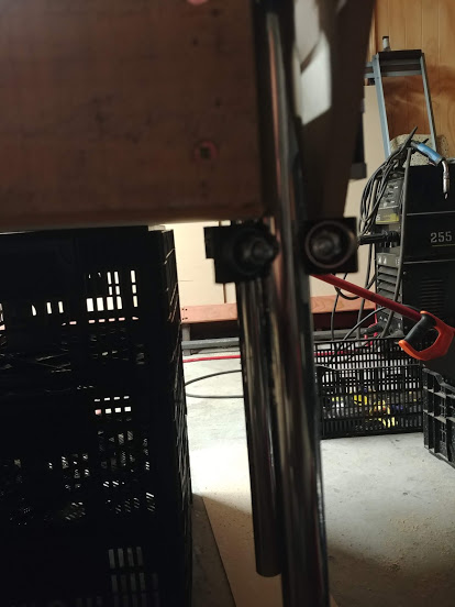
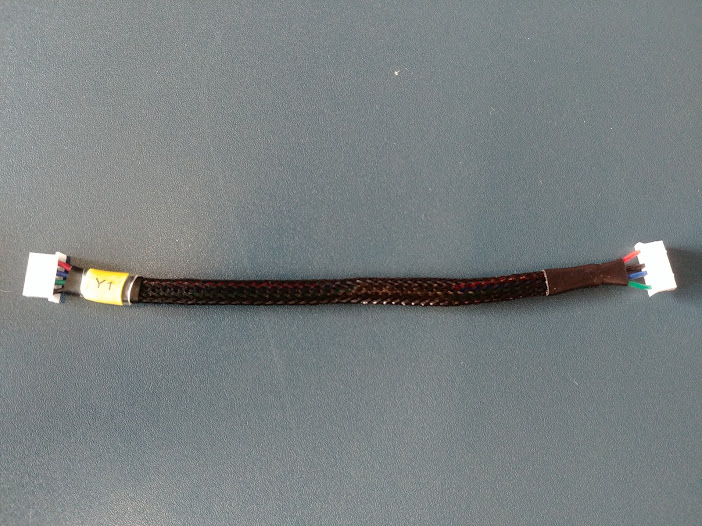
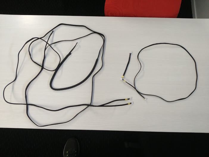
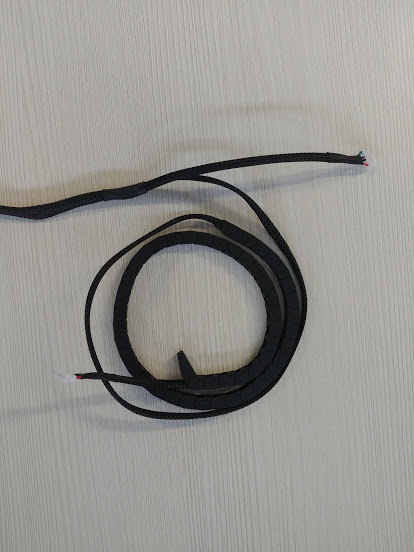
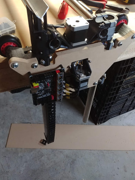
So, got the wiring done… Looks pretty good i thought!? didnt have enough to do X, so thats just dangling in the breeze ATM but more showed up today, so will fix that this week

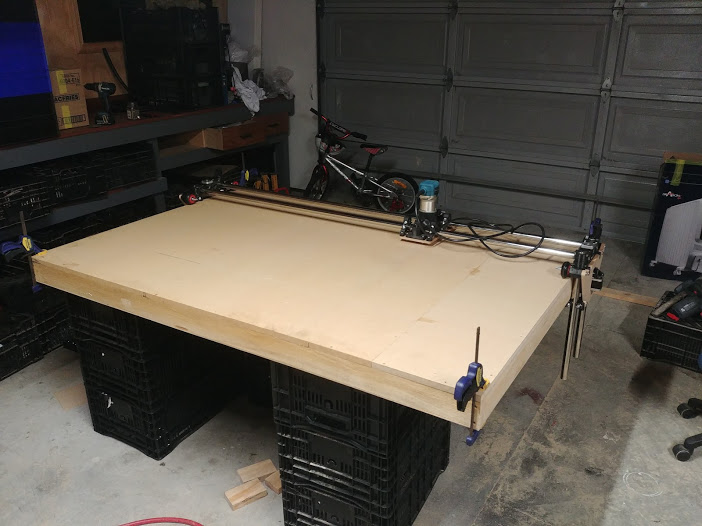
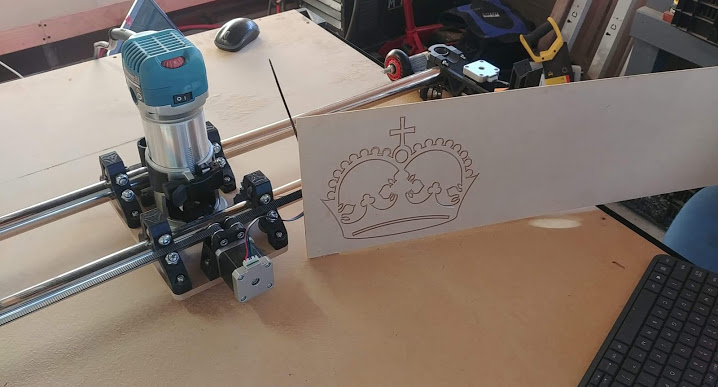
Here is a video of the first run of the LR2!!! didnt have a pen mount, and had my buddy around and we felt pretty confidant… so went with an engraving bit. Held the material by hand because we life our lives on the edge etc haha. It’s long, so just skip lots as nothing happens in the middle of the video

but this is it! a crown! we moved the board a little in a couple places. Took ages as it did 2 passes, but so be it… it made dust and im happy!

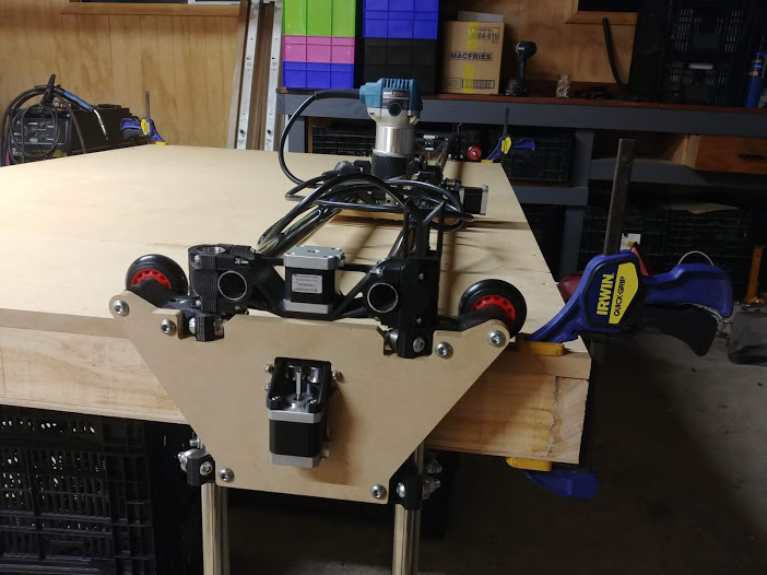
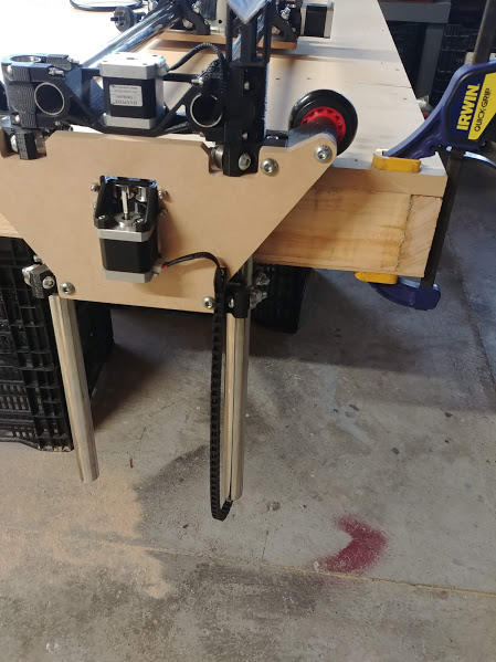
We did another one where we tried to do a calibration square/diamond/circle thing, but X stopped working… figured it was loose so cable tied in some strain relief and tried again. This time it worked, btu did a WEIRD thing…

It machined a pocket, then moved up 5mm above the work piece to move to the nexy pocket and then moved down to 1.6mm above to start ramping down into the piece again, but it only moved down a fraction of that, so it milled air for ages and the cut was only a couple mm deep. Then on the next move to the next pocket, same thing! moved 5mm proud (which was then 7 or 8 mm proud because of the previous fuck up) and then down but moved a fraction, so this time it even touch the material at the end of the 5mm deep pocket…

We checked the G code, and it is fine. The machine says it things it’s at -1mm for the first pass, but it was still 5mm clear of the material. First pocket was perfect though, so makes little sense.

Not sure if my explanation is garbage or not sorry… but i’ll spend a bit more time on it this week and see what we can make of it.

In positive news, my buddy Cam who came and helped me was reasonably impressed with the machine! He cut my plates at his work, where they have some FANCY machines! He was a little confused when i was talking about 15mm/s feed rates etc and laughed at me when doing 1mm passes on the first run, as they run 10mm cutters at 18 meters a minute through a 3/4" sheet in a single pass :open_mouth: :open_mouth: :open_mouth: :open_mouth:

2 Likes

DANG!!! That would be cool to watch!

here you go then :slight_smile:

https://www.youtube.com/watch?v=5gEhlyP8DDc

Needs it’s accelerations tuned!

That is pretty awesome otherwise, looks like it can handle some crazy operations.

Looks similar to some of the machines in one of my client’s buildings. It’s 5 axis.

1 Like

Are you sure it isn’t? The bigger the gantry, the lower the accelerations, right? Maybe it’s just that big.

It slows down so much for those corners and you can hear it screech. I bet it can go faster, but maybe it is tuned for metals? I can only imagine the cool parts that come off a beast like that!

It does seem slow in the corners etc. They do plastic and wood on those machines usually, not metal… not sure why it seems slow in the corners, but im definitely no cnc operator haha.
But for reference, that beast is their small machine :wink:

Anyone maybe have a place for me to start looking regarding my printer moving weird in Z?

so pocket to -5, move to new pocket at +5 all seemed good
then move to +1.6 to start ramping into the material, but seemed to have moved to +3 ish
pocket to -5, which ended up being ~-2
move to new pocket at +5, which was high at +8 or so
then move to +1.6 to start ramping into the material, but seemed to double the error to +6 ish

G Code looked fine… all the numbers made sense, and the controller even said it was at -1 when taking first pass, but it was very much up in the air

99% of the time it is your Z rapid speeds.

1 Like

G’day Ned - how did you go getting the SKR 1.3 to work? Was it difficult to get the firmware operately correctly. Well done on the build… amazing… and thanks for the part list


It cuts! I have a lot to learn still, but i made a thing! I also need a new phone as the glass over the lenses of my cameras have smashed so everything is a blurry dusty mess… but it works!!

SKR wasnt toooo bad. Its nice having sensorless homing as well!
I home Z on max as to not destroy the lead screw couplers, and that works ace! I printed some clamps to clamp onto the tubes that act as stops, so i can level the Z and act as end stops.They have to be good though, or they move when you accidentally travel past the stops haha and they move and ruin your setup :stuck_out_tongue:

1 Like

I am using the same set up by my SKR 1.3 and TMC2130 but my take printable area is 36 x 60 and I am planning on using the end stop switches . Can you please hook me up with your firmwire( software to load on the SKR1.3) .I will be highly appreciated .

2 Likes

Nice work!

I just switched all my wiring from series to one cable per stepper motor to be able to add sensorless endstops.

I would really appreciate if you wanna show how you achieved that in detail? :slight_smile:

This is an old old post. We have docs now. If you still have questions open a new post and I am sure we will figure it out.

https://docs.v1engineering.com/electronics/dual-lr/

Holy smokes. Didn’t realize this. Thank you!

1 Like