After some years into my 3D-printer journey, I want to dip my toes into CNC milling. I chosed the lowrider 2 due to the large print (not print… cut?) volume to a low cost.
My progress so far:
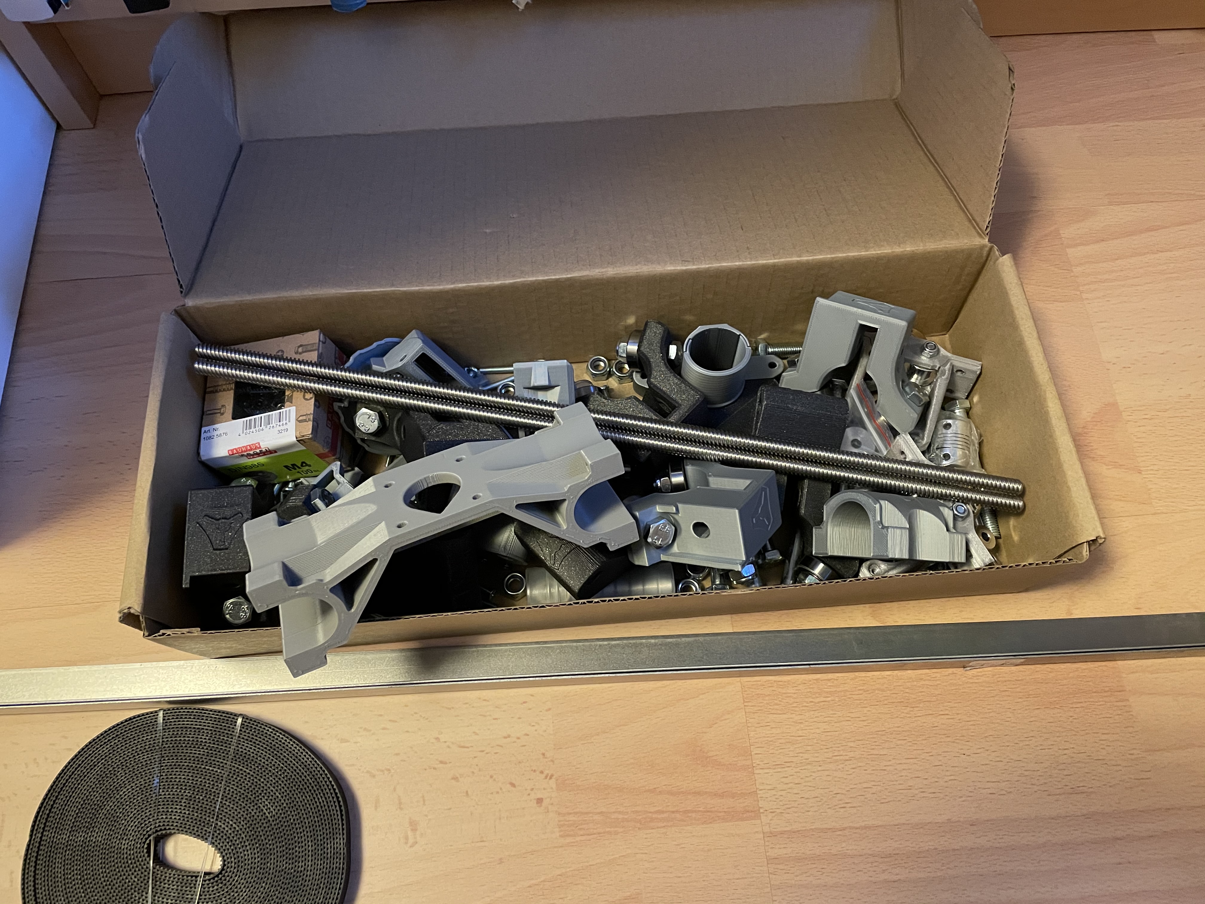
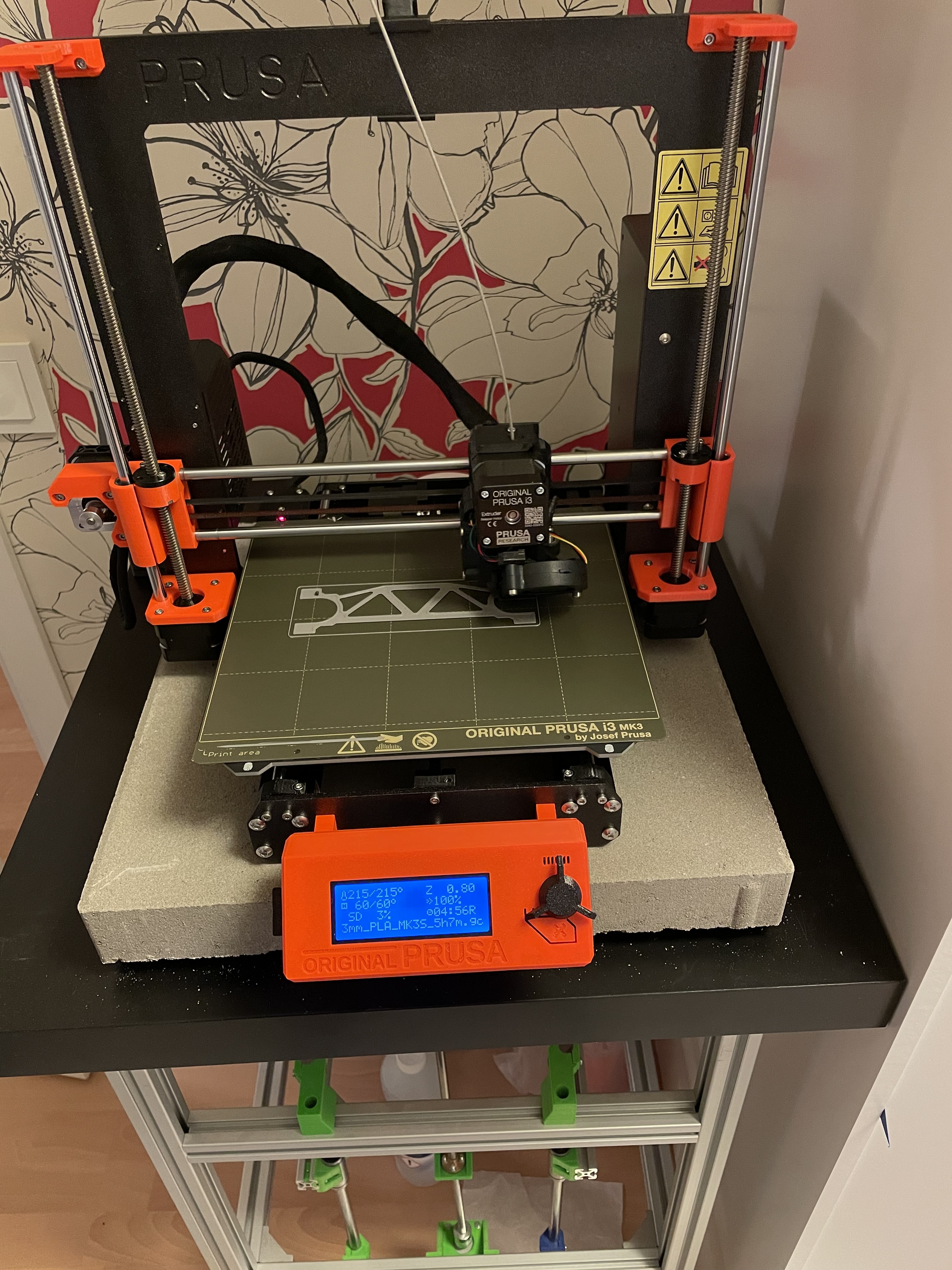
Print all parts (Almost done)
Source all hardware (Done)
Cut the plates (Not started)
Source electronics (I have some Nema17, BTT SKR mini 2.0, etc from 3D-printer builds that I hope to reuse)
Test the electronics
Source the End mills and other miscellaneous parts
Assemble everything
Thank you Daniel Silén for the great tips on the wardrobe rail:
Thanks! Yes, it works wonders for the sounds/vibrations from the printer (with some foam under the block). I first saw this in CNC Kitchen on YouTube. I highly recommend it!
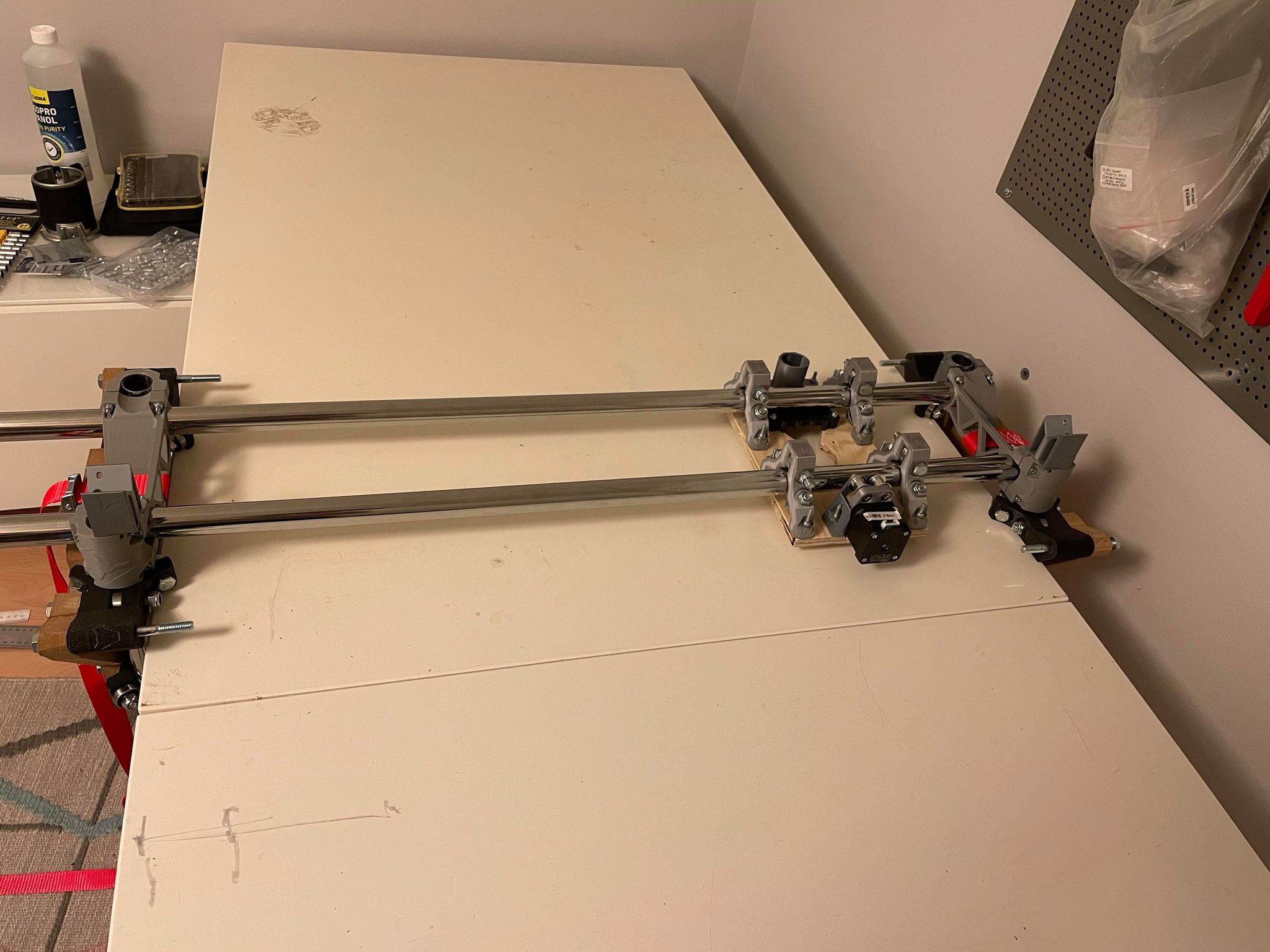
I have now begun with the assemby. The plan is to have the Lowrider in my unheated garage, but it is still freezing cold in Sweden a the moment, so I have done a test assembly in my mancave.
One comment regarding the assemby: The lack of nut traps in the printed parts is really killing me. The need to use needle pliers on almost all screws makes the build both time consuming and frustrating. We really need nut traps in the next revision
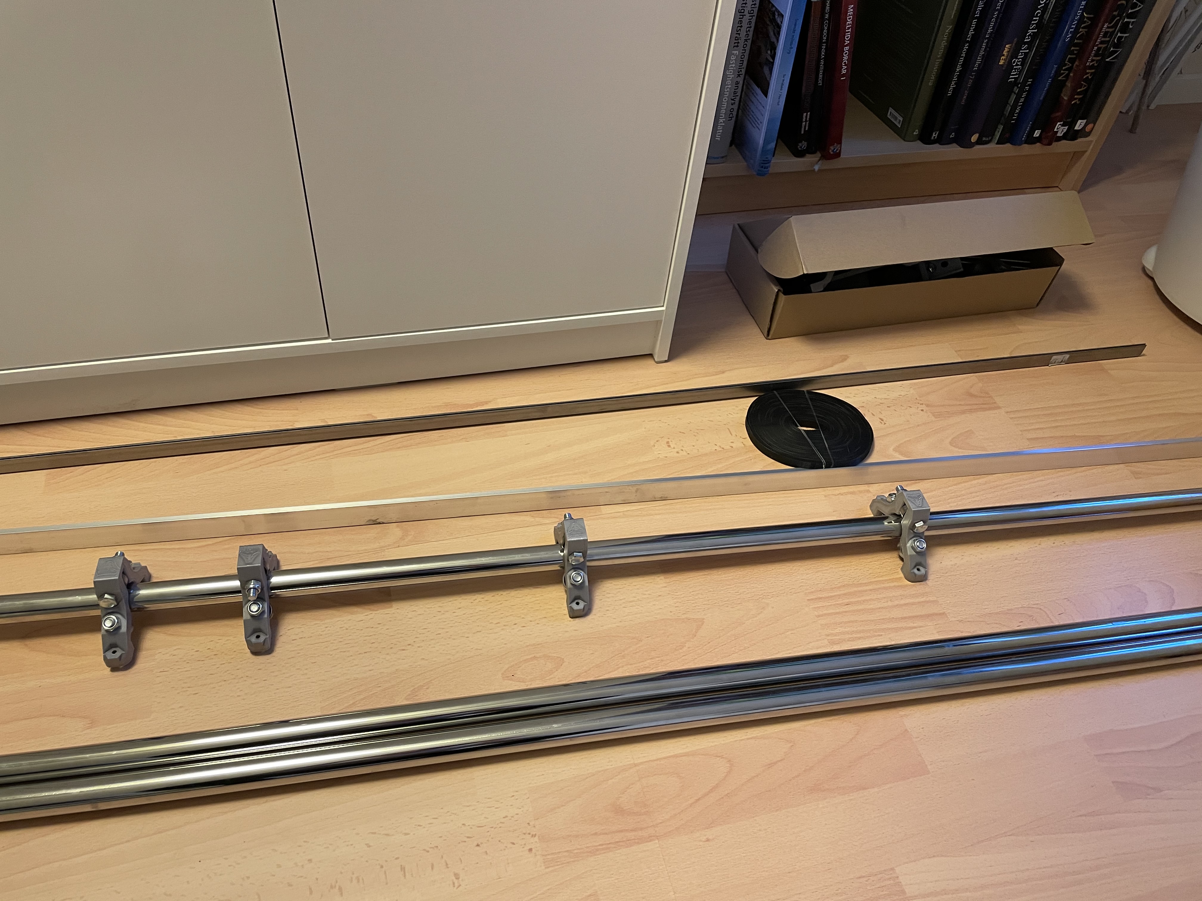
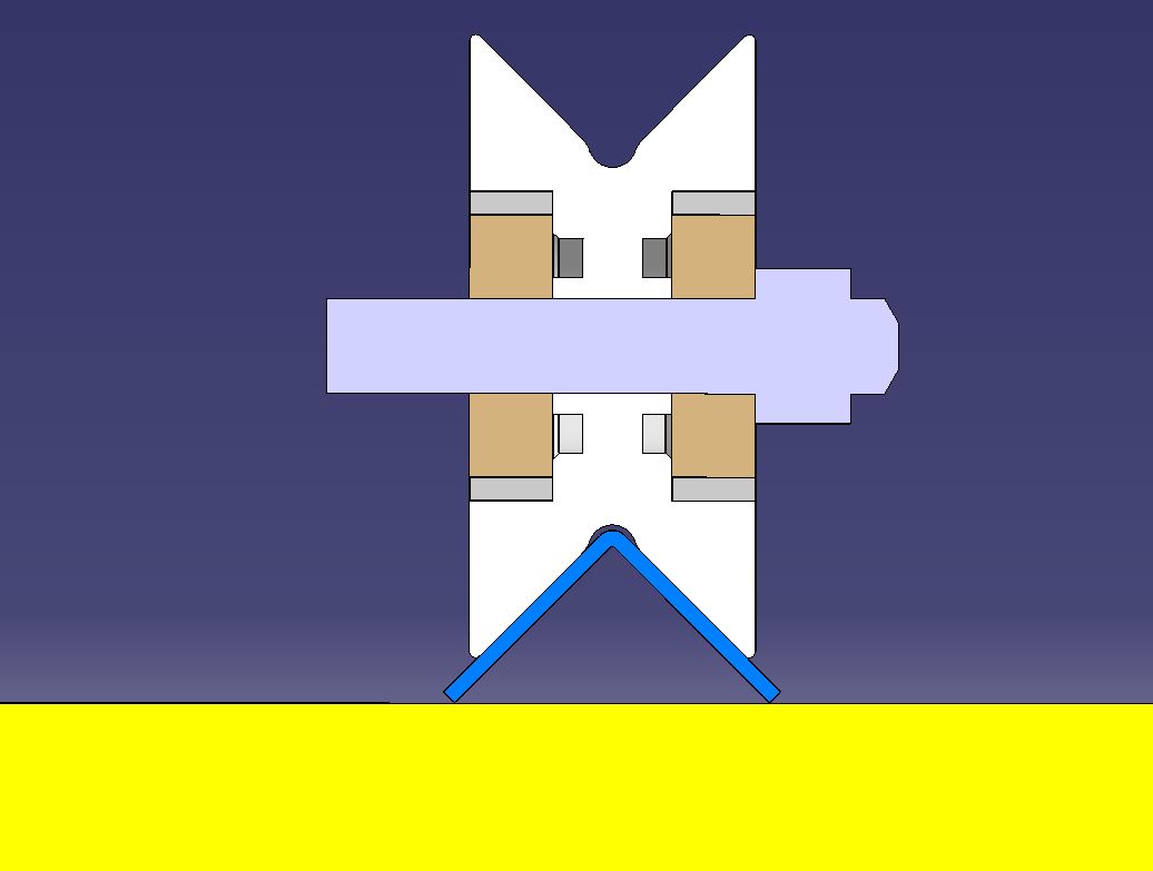
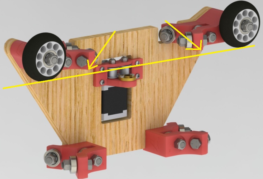
The plan is also to use 20x20x2 mm steel L-profiles for Y-axis guides, and I’m printing out V-groove wheels to adapt to that. It will look something like this:
I did not use any pliers when tightening the nuts, only a small flat head screwdriver. But yes, a bit tidious.
Those wheels will really make the LR2 run straight. Thinking about doing the same, maybe I can use your files? To prevent dust under the wheels I just added a L-profile beside where the wheels run.
I made the wheels 60mm in diameter, only to find out that the L-profile will clash with the wheel brackets… So the wheels needs to be around 100 mm in diameter to get clearence for the L-profile.
So I paused that and printed out 60mm regular wheels in the meantime. Maybe I will design and print out larger wheels later on, and then I will share the files.
Isn’t that what we would want? Less friction along the axis? There’s plenty of friction going on with the spindle, steppers, Z-lead screw, bearings; the wheels ought to not add to the problem. Plus, with how he will be removing the drift potential by using an L to keep the Y parallel one would think grip on the surface isn’t needed anymore.
@Qvast Any news regarding your V-shaped wheels?
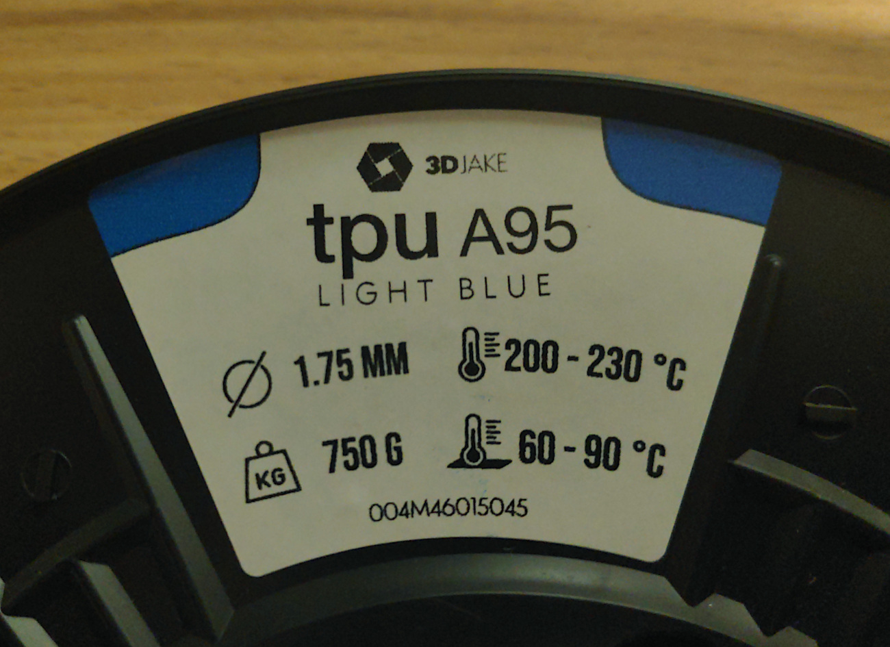
I am just starting to build a LowRider2 and thought of printing such wheels in TPU with a shore hardness of A95.
This type of material feels just like the rubber of tougher wheels.
Think I still do not understand the problem to the full extend.
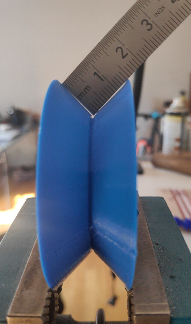
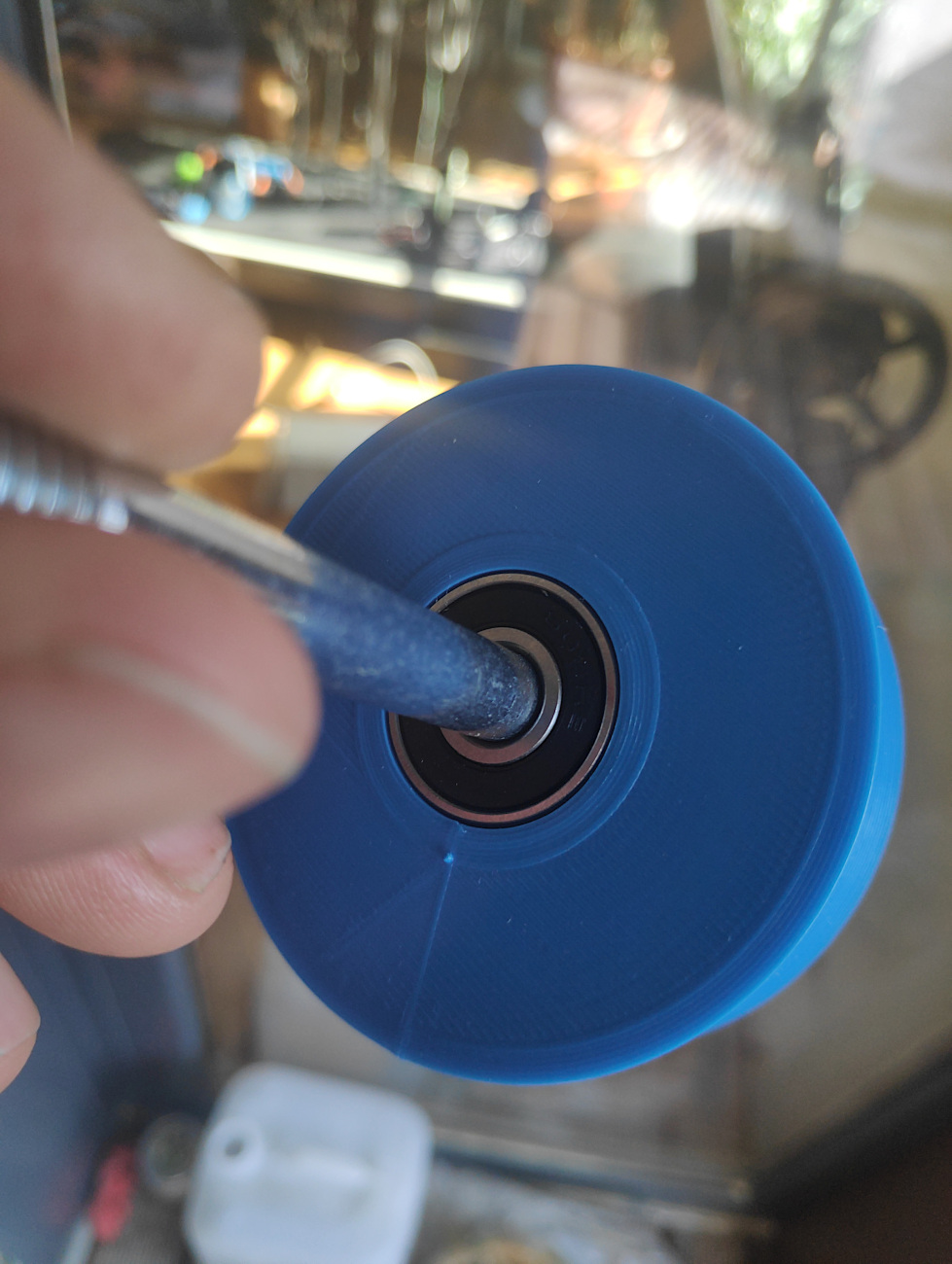
I just designed and printed a wheel with a inward groove 60mm heigh and 20mm wide in TPU.
The model can be downloaded from the prusa website here.
When I measure one side of the groove I get a bit less than 15 mm which would be ideal for a 15x15x2 mm L profile.
I still can not see where the L-profile will clash with the wheel brackets.
Please can you explain to me what my mistake in thinking is?
Ah, ok. Now I understand! Thanks for clearing things up.
Did not take these rollers into consideration. Its a pity because the wheels with the groove would be kind of self centering and the upside down V channel could not be clogged with debris easily.
Yes - I thought of that too. Just will have to wait till I have started with my lowrider build so that I can measure how heigh the new wheels actually will have to be.
Right now they have a height of 60 mm. The height of the 15x15 channel should be around 10mm. When the Z-Roller is about 7mm above the board - like @Qvast said - the new wheels should be at least 2 x 3 = 6mm higher than this ones.
According to this calculation, a height of 60 + 6 + 2 mm clearence (=68mm) should be enough.