I quite like the idea of inverse V wheels running on an L profiles fixed to the table. It would be fairly easy to ensure the profiles are parallel down the length of the table which would stop any slight wander. Also there would be less of a chance for dirt to build up to a level that would cause problems.
Would a PLA wheel hold up to the strain involved do you think?
I guess PLA would fail in the long term.
Probably TPU with a shore hardness around 95A would be a better choice. I reckon this is why the wheels of skateboards and shoe soles for example are made with a similar material in a similar hardness. Here is a more detailed overview of TPU. In my experience it is not so difficult to print as it is described in the website mentioned above. Polycarbonate or nylon might also be a good material for this purpose but I have to admit that I never have tried out any material under these circumstances .
I am still just at the point in my build of having a bag of 3D printed parts but I just measured on of the rollers and came up with a 6mm gap between the bottom of the bearing and the surface of the table.
So to make this work with a profile size any larger than 5mm above the table surface the diameter of the wheels is going to have to increase, unfortunately I don’t think you could go much larger on wheel diameter before it starts fowling on the roller body and bearing bolts.
Interesting idea, that would make the Y plates sit higher meaning you would need to have the rail lower than the work surface to retain the same Z height, as you show in your picture.
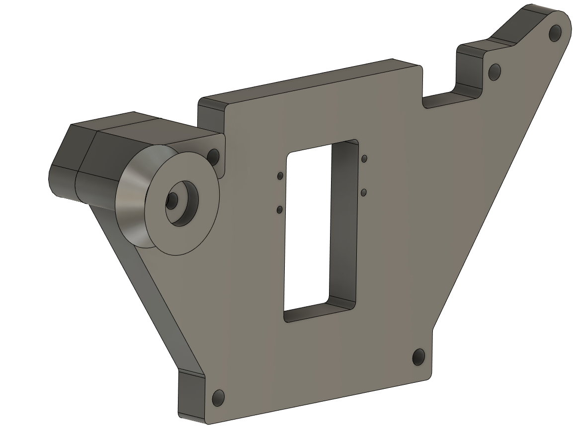
Looking at the 3D printed parts it would appear that the only piece that would need to be modifies would be the Y plate as you could just use the current 3D parts rotates and flipped to the other sides.
Also just noticed your Y stepper is inverted, I am guessing that the flipped rollers fowled against the belt in the original location?
Yes exactly, but I wanted the rail lower anyway to make it easier to slide large sheet goods on and off without contacting the rail so it worked out perfectly for me. You could try just flipping the existing parts, but there were subtle differences so to be safe I modified them in CAD by splitting the part and flipping just the wheel mount portion and then re-joining.
If I remember, the normal Y stepper configuration put the belts too high for me. I’m using EMT conduit and pulley wheels to keep things centered, and the normal configuration would’ve put the belt mounts too close or overlapping with the conduit, so I just flipped it. I don’t remember any actual obstruction with the flipped parts but I could be wrong.
Well I’ve had a quick mess around with some CAD files this afternoon.
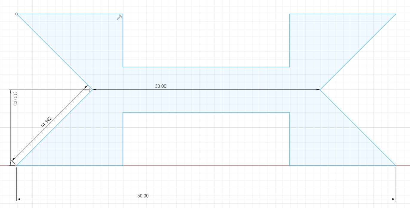
Comparing the two Y Rollers it would seem to me that you could just swap them over and rotate them without any need for modification. Using some 15x15mm angle and wheels with an OD of 50mm and an ID of 30mmwould raise the Y plate by approx 21mm.
From what I can tell the belt would clear the inverted roller assembly’s but, due to the Y plate sitting higher, the belts would now be above the table surface rather than beside it. It would make sense to me to do as Josh has done and flip the Y stepper assembly’s to lower the belt down placing them beside the table again.
I am not quite sure what the ID of the wheels would be?
All in all it looks quite promising - cant wait till my all my parts come and I can start building.
Ah, ok - I understand Thanks for explaining
As far as I understand the inner diameter would not interfere with the whole setup since all the measurements only depend on the height of the center of the wheel.
On a wheel that the 20mm wide the inner diameter of the grove would need to be 20mm smaller than the outer diameter of the wheel in order to give the correct 90 degree grove. The actual face of the grove is just slightly less that 15mm which should allow it to roll along nicely on some 15x15mm angle.
This is my first Lowrider, first CNC altogether actually, so I am slightly torn between making it totally stock and getting it working before worrying about any mods and making some mods during the first assembly.
I do really like the idea of having the V wheels to give the whole Y axis a bit more support and guidance.
Might get both stock and modifies Y plates made up and see how things fit together when I actually start building.
Now I realize that I had misunderstood you before. I thought the inner diameter is the cutout for the bearings. But it is the inside diameter of the V shaped wheel. In this case I totally agree.
I am in the same situation as you. Its also my first CNC build and I already have ordered the Y-plates to be laser cut. I think I will first build a stock Lowrider2 and then use it to create the mods.
 !
!
 Thanks for explaining