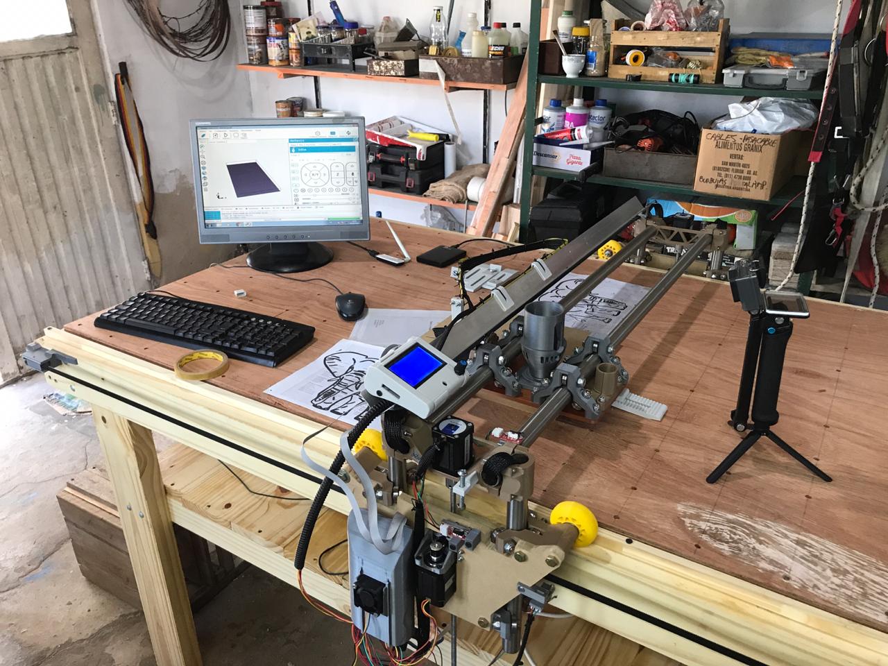
Hi everyone, I’m from Argentina and I’m starting my Lowrider 2. The crown drawing test went well. I also tried some engraved and they turned out well.
My first machining test was the following and I got out of track and before reaching out and getting worse I prefer to consult. The things I thought:
I am using an old computer, even repetierng does not load the image of what I am going to machine. Maybe at some point there is no good connection with repetier. I am using a USB extension cable (maybe some data will be lost at some point)
Lost steps? The DVR 8825 drivers were calibrated.
The GCODE looks good and the simulation in Fusion 360 looks good.
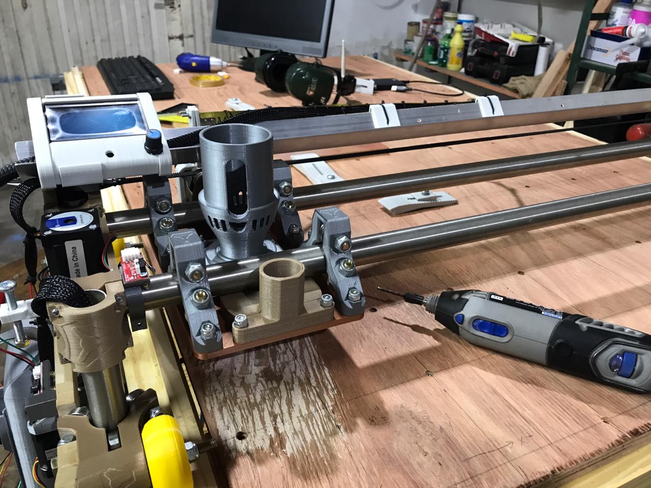
I am using
Dremel 4000 for cutting
3.175 mm diameter carbide .
The cutting speed is 1300 mm / min and the travel speed is 2100 mm / min in x and y; 240 mm / min in Z.
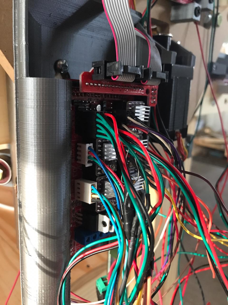
Ramps 1.4 with dual endstop.
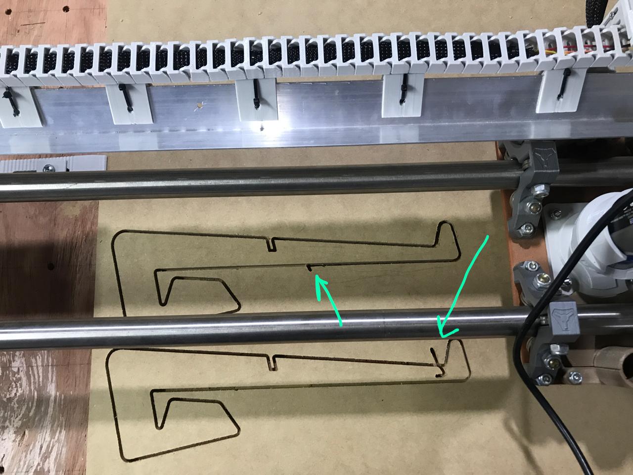
The two times the problem appears when the tool should have gone out and traveled to machine another drawing from the top.
Maybe tomorow I will try cutting from SD.
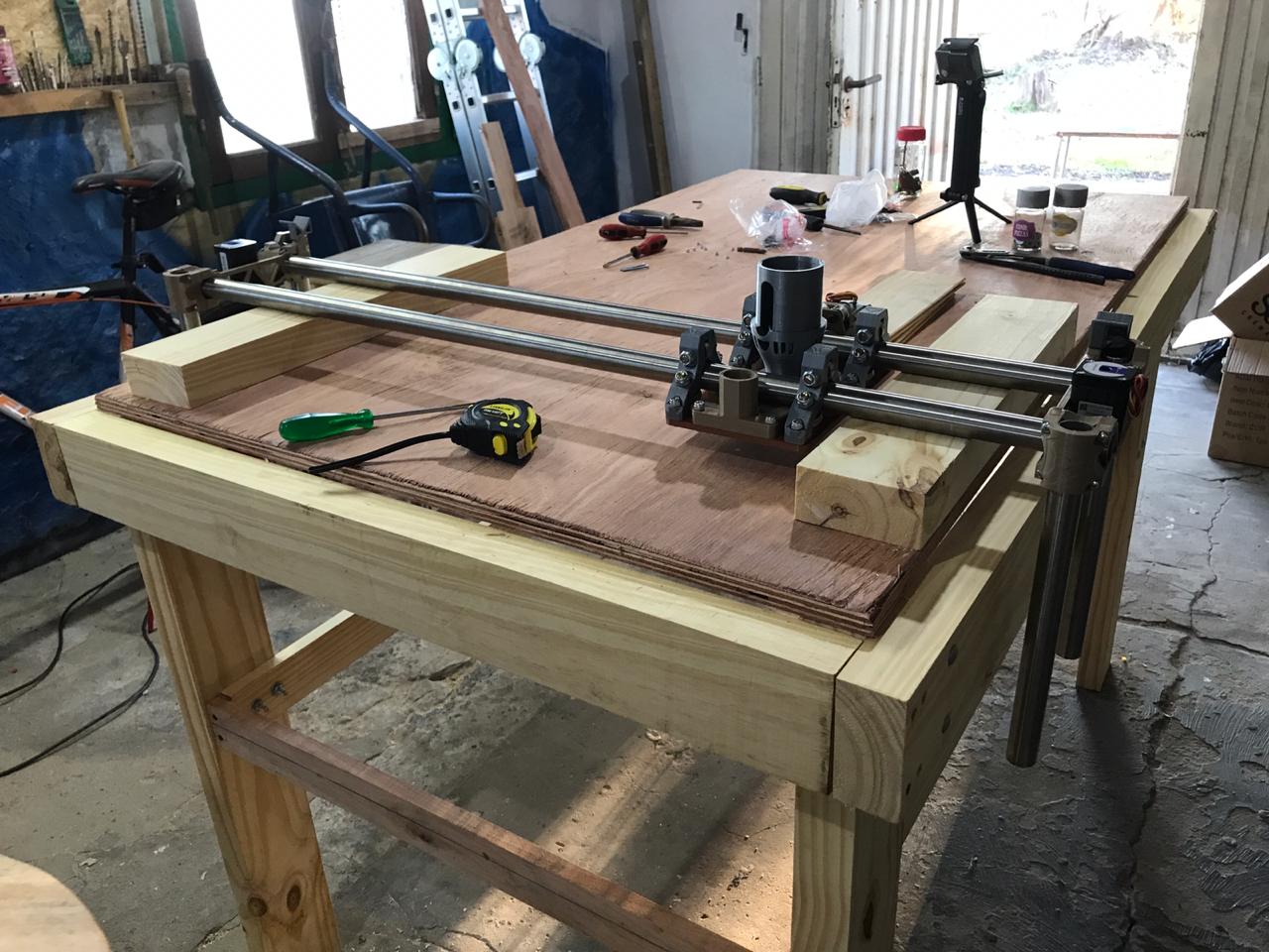
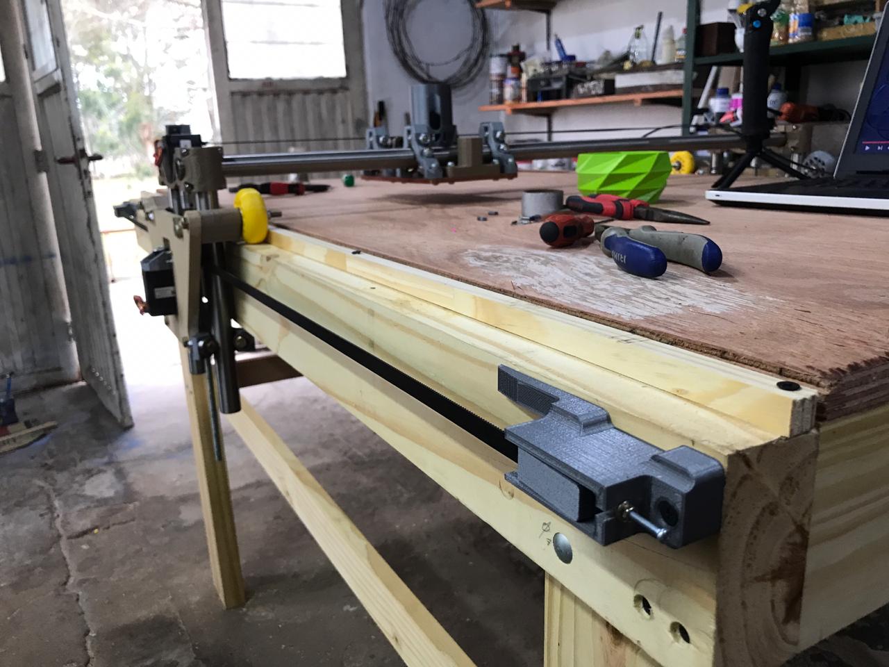
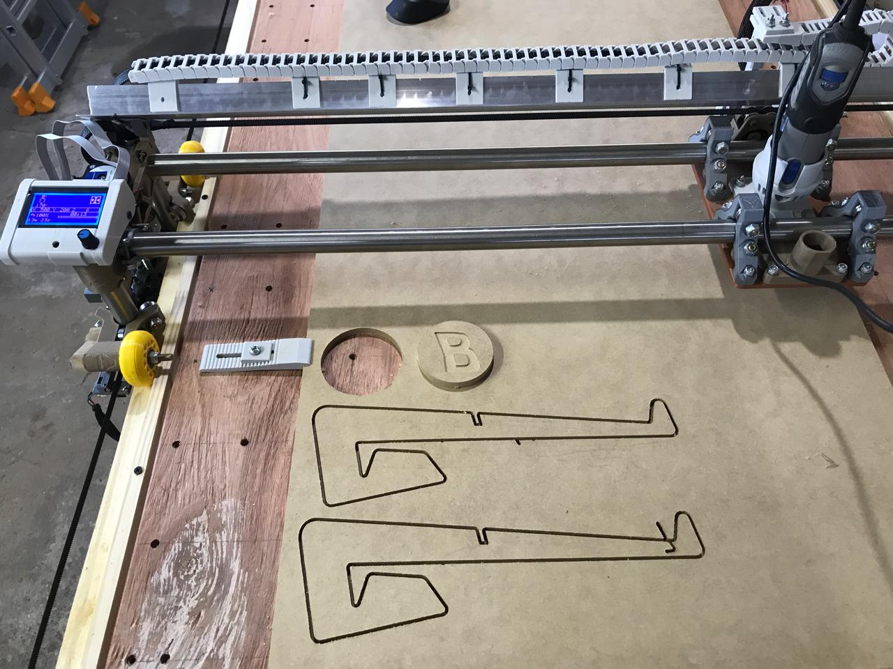
I leave some picture of the problem and from the machine. Sorry for my english! Thanks for everything
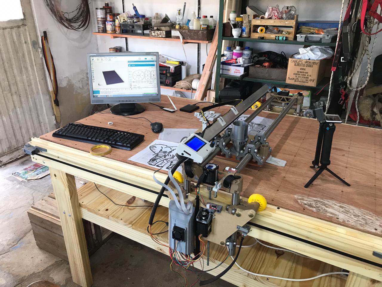
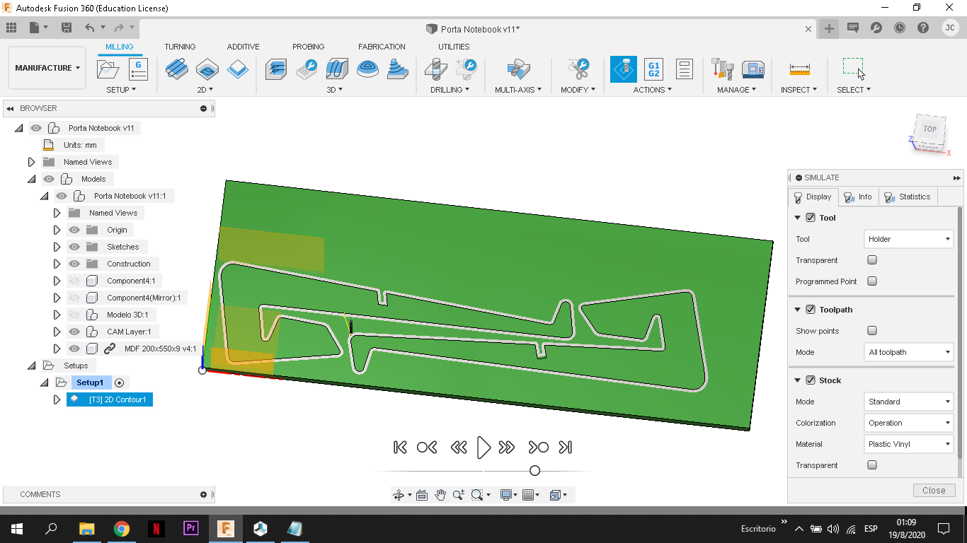
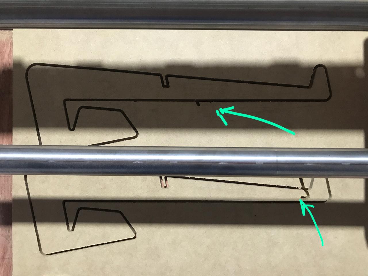
It may seem that the photo does not represent what is drawn in Fusion 360 but it is because when the error appears, I canceled the machining and started it again and the error was repeated but in another x,y,z point.
A couple things to try. First put a pen instead of the Dremel on the machine and see what you get. I cannot tell from the snapshot of the CAM what you are doing, but consider multiple passes and include a roughing pass with 1 stepover for your 2D Contour cut. Might also want to dial back the cutting speed a bit until you have this problem sorted out.
There is a setting called “show travel moves”. You need to turn that on to see the tool path in the preview.
Keep an eye on runout. If it is chattering a lot just before it does that, then it might be the router biting more than it should.
1300mm/min is pretty quick. You didn’t mention the depth of cut and you didn’t mention which pass this failed on. But I would reduce that 1300 to 480 first. The 2100mm/min isn’t so bad, but just to be safe, I would bring that down to 1200.
This makes it sound like it should have lifted, but couldn’t. Is that right? The Z speed seems fine. Does your Z travel 10mm when you jog it 10mm?
I check that and it is not working.
I still haven’t got a good look, but it seems like he’s digging into Z before making the mistake. The machining was down to -9.3mm (-9 mm for MDF wood and -0.3 mm for be sure) and one of the figures was about to finish but instead of leaving the “first drawing” and going to the “second drawing” it seems like if I go deeper into Z.
I will do this. I think it will help me.
It is important to say that I am using M8x1.25 rods, so I modified the parameters in the Marlin.
It changed the steps per mm in x and z so I use a 20 tooth pulley instead of 16 in the X and Y
and I use M8 threaded rod instead of T8 trapezoidal rod.
To calculate this in X and Y:
steps_per_mm = (steps_per_motor_turn * microsteps_of_driver_of_the_motor) / (pitch_between_pulley_teeth * number_pulley_teeth)
And in Z:
steps_per_mm = (steps_per_motor_turn * microsteps_of_motor_driver) / rod_step
In my case:
Nema 17 motor steps: 200 steps. (xq are 1.8 ° / step, so 360 ° is 200 steps)
Driver microsteps: 32 (because I put 3 jumpers below the drivers)
GT2 pulley tooth pitch: 2 mm
Number of pulley teeth: 20
Threaded rod M8x1.25
/ **
- Default Axis Steps Per Unit (steps / mm)
- Override with M92
- X, Y, Z, E0 [, E1 [, E2 …]]
- /
#define DEFAULT_AXIS_STEPS_PER_UNIT {160, 160, 5120, 160}
When I test it was ok, but I will check that it is moving correctly.
With the M8x1.25 rod, the Nema 17 motor has to rotate many more times than if it were the T8 to travel the same mm so it will probably have to reduce the speed even more in Z so that it does not lose steps.
I’m going to check all that and write to you. Thanks for the help!
Sorry I forget this. I im using multiple depths in Fusion 360 with 1 mm pass and its looks like the error was during the last pass of the first drawing.
But I will change the speeds and tell you. ![]()
Ok. I think the problem is with the 5160 steps/mm. That means your motor has to turn a lot faster to be able to move at the same speed. Steppers aren’t as strong when going fast. So even though you’re only moving at 4mm/s, your motor is moving 6x faster than a normal mpcnc with a lead screw.
Here’s what I would do:
-
Make some test gcode to just go up and down over some larger movements. These “exercises” will help test the next steps. Hopefully, it will skip now, and not later. Something like this:
G1 Z50 F240
G1 Z0 F240
G1 Z50 F240
G1 Z0 F240
G1 Z50 F240
G1 Z0 F240 -
Run that gcode without and with the router on.
-
Set the max feedrate on Z lower like this (this command is mm/s, not mm/min):
M203 Z4 -
If you find a speed that works, drop it a little more and then save it with M500.
There may be an issue with your gcode exceeding the F240 on that move, so F240 may still be ok. But setting that limit in Marlin will keep you safe.
Great, I will start doing all that. Some questions:
This I have to do it from marlin?
Sorry for my ignorance.
As a last option I have to think about buying the T8 and changing my system. But first I’ll try all of that. When you can tell me how to change those parameters. Thanks again.
/**
- Default Max Feed Rate (mm/s)
- Override with M203
-
X, Y, Z, E0 [, E1[, E2[, E3[, E4[, E5]]]]]
*/
#define DEFAULT_MAX_FEEDRATE { 120, 120, 30, 25 }
My marlin is like this. Were you talking about that?
Change 30 to 4?
As usual…there is more than one way to achieve this result. You can alter the max feedrate as you suggest, then re-compile the firmware and upload the new firmware to your board…or you can override what you have in the firmware by doing as Jeff suggests and write the required new value and then, when you are happy with the new figure you can save the new figure to the eeprom so that it overwrites the old wrong value with the new right value from eeprom every time you reboot the board…choose whichever you are happy with.
change the 30 to 4, save it, recompile it, upload it or
at the console enter M203 Z4 and try the machine, if it works ok enter M500
Ok, when you say
obviusly is from repetier, no?
And if it works after some tests and
In repetier too? M500 would save this configuration without having to change the 30 to 4, save it, recompile it, upload it from marlin?
Yep, the gcode console in Repetier Host (or whichever gcode sender you use).
This is all correct. One caveat. If you just change that value and flash, Marlin doesn’t know if you just updated the firmware or not, so it will still use the value from eeprom. So you have to send “reset factory defaults”, which is M502, I think.
good point!..that dratted eeprom is more bother than it is worth 
" So you have to send “reset factory defaults”, which is M502, I think."
M502 - Revert settings to “factory” defaults. (Follow with M500 to init the EEPROM.)
//#define EEPROM_SETTINGS fixes all eeprom issues!
Ok, I did everything proposed and did a smaller test to see if I found any errors and so far everything is fine.
By doing this everything went well and responded to the heights entered
I change from marlin #define DEFAULT_MAX_FEEDRATE { 120, 120, 4, 25 }
And also set the fusion 360 so that the z-speeds are 240mm / min just in case.
The speed that exceeded that was Ramp Feedrate which was at 333mm / min.
Change the value on the post processor from 2100 to 1200 mm/min in x y; 240 mm/min in z
In Fusion 360 instead of 1300 mm / min I put 500 mm / min.
A doubt regarding this:
I change the value in marlin. After that I have to put M502 follow with M500 to init the EEPROM in repetier? I thought that once the marlin was corrected and compiled, the value would remain. I am a beginner and I don’t know what EEPROM is.
I leave a photo of a small test (cylindrical cut with an engraving of a B)
I will try to do the other figures and tell you.
Thanks again
EEPROM stands for Electrically Erasable Programable Read Only Memory which is a bit of a misnomer as you can write to it by erasing and writing new values…anyway, this memory will survive powering down so is useful in storing temporary values and that is exactly what it does here, it stores a temporary feed rate and the software is arranged to read the eeprom when it boots up and use those values instead of the values stipulated in the firmware…so if you change the firmware you have to tell the eeprom to use the new values or else it will just load the old values, so the M502 you send from repetier host tells the eeprom to read the new values from the firmware and the M500 tells the eeprom to store the new values for future use.
It is possible (some (I) would say desirable)… to disable the eeprom so you cannot change the values from those values stipulated in the firmware…but that discussion is for another day!
The short answer is yes, you have to use M502 to reliably get the values out of the compiled software. I’ll explain a bit more in case you’re interested in understanding it.
There are three kinds of storage in the microcontroller. Program space, eeprom space, and what I’ll call “runtime space”. When you compile the code, it creates everything that needs to go into the program space. When you flash it, it replaces everything in the program space with what you compiled. Your 4 is in that space right now.
When Marlin is running, it doesn’t use the parameters from the program space, it uses the ones in runtime space. When it boots, it decides what to put in that runtime space. You can change what is in the runtime space with gcodes like M203. When you send that, it changes what Marlin is currently using, but it can’t keep the runtime space when it shuts down. The runtime space isn’t persistent.
So you can save the parameters from runtime space into the EEPROM. You can’t save the runtime parameters into program space (because of reasons) so Marlin has set up the EEPROM to allow you to edit some parameters after you’re running, and then save them to EEPROM. This is what happens when you send M500. It saves the runtime parameters to EEPROM. In the next boot, it will start the runtime space with whatever is in the EEPROM space.
If you change the values in the program space, by compiling new firmware, but you don’t change the EEPROM values, then Marlin will still just read the values from EEPROM and put them into the runtime space. It doesn’t know that it just was flashed, it only knows what is in the EEPROM. (There are some exceptions, if you upgrade to a new version of Marlin, it will see that the EEPROM probably isn’t valid and delete it, or if it is a new chip where the EEPROM wasn’t ever initialized, it will also treat it as invalid and delete it).
So when Marlin boots, it will read the values from EEPROM and put them in runtime space. When you send M502, it will read the values from Program space and put them in runtime space. M500 will take the values from runtime space and save them to EEPROM. Rebooting Marlin after that will read the values from EEPROM and put them in runtime space each boot.
If you want to play with just the speed, you can use M203 to change the value in runtime space over and over, and if you’re ever not happy, you can just reboot Marlin, and none of those changes will be saved. If you like that value, you can save it to EEPROM with M500.
Both great explanations. It is perfectly understood. Thank you very much for your time. I will continue with the tests. If any inconvenience arises I will try to disturb as little as possible.
Super clear, thanks again and I hope I don’t have to bother you too much!