I didn’t realize estlcam could do a carve with a png or jpg. Interesting!
I know what would work, is to convert it to svg by using inkscape.
import the png into inkscape
use the bitmap tracing tool. There are some good videos, or here is some documentation. It basically converts picture shapes into edges in svg: Inkscape tutorial: Tracing bitmaps | Inkscape . A black on white image like that will be easy.
delete the imported image.
You may have to convert the traces to paths by using the convert object to path tool.
save as svg
Import the svg into estlcam and the. Choose pocket.
Estlcam also has a basic text tool. I would make a dxf with the rectangle shape of my workpiece. Open that in estlcam and then add text.
IDK what affinity is. I am not an expert at these graphic design programs. I do know that svgs can store fancy objects like ovals, arcs, rectangles, text, or it can store the same shapes as paths. In inkscape there is an object to path button. I have better luck saving svgs that only have paths for estlcam. Maybe affinity can also convert the text to paths before exporting it as svgs.
In the past I´ve used Adobe suite a lot, that´s until they swapped to a monthly fee. As I didn´t use it that much anymore I couldn´t get myself to pay a monthly license. So that´s how I came across Affinity.
They are a competitor for Adobe, with low one off fee. They are great, although sometimes they have some missing features like in this case export to DXF.
But you´ve given me a lead, I think I did not convert my text to path/curves/outlines before exporting to SVG. So should try to do this. And if not working, try to convert to DXF.
Regarding Inkscape, I think I´ll try to convert using Photopea | Online Photo Editor instead, as it is compatible with photoshop and can export to DXF.
I am sure there will be many new chapters soon!
Small update on my probing challenge;
I´ve successfully managed to probe. However for some reason the Z refuses to lift after probing to the predefined height, so I could remove the probe.
I used the following 2 scripts, but no luck for the G0 and G1 command. If someone spots my error, please share!
G21 ; Set units to millimeters
G90 ; Absolute positioning, just in case
G38.2 Z-400.000 F500 ; Probe Z from max Z height, in case it was homed
G92 Z14.000 ; Set Probe offset to 14mm, thickness of probe
G92 X0 Y0 ; Set X Y axes to 0 from this point on
G0 Z200.000 ; Raise Z to remove probe
G21 ; Set units to millimeters
G90 ; Absolute positioning, just in case
G38.2 Z-400.000 F500 ; Probe Z from max Z height, in case it was homed
G92 Z14.000 ; Set Probe offset to 14mm, thickness of probe
G92 X0 Y0 ; Set X Y axes to 0 from this point on
G01 Z200.000 F500 ; Raise Z to remove probe
I probably would not raise Z to 200 from 14. Too time consuming and not needed just to remove the probe.
G0 is probably the correct code to lift Z (That’s what I use) but I see that you didn’t have a feed rate specified. F500 is pretty slow, and raising 186mm at 500mm/min takes something over 22 seconds, which is quite a long time for setup.
I lift mine by about 9mm, which is plenty to remove the probe. I also use a relative move for this.
You can optimize a little better with the G92 commands, there doesn’t need to be 2 of them in a row, you can set all 3 axes (G92 X0 Y0 Z14) though I would have set X and Y manually earlier, myself.
I use M400 commands to be sure that the machine has stopped moving before G92 commands. It should be fine with probe moves, but it’s a habit for me to explicitly wait for the machine to stop moving first.
So for me, that might look like this:
G21 ; Set units to millimeters (This is pretty safe to assume that it's already set for me.)
G90 ; Absolute positioning, just in case
G38.2 Z-400.000 F500 ; Probe Z from max Z height, in case it was homed
M400 ; Wait for movement to stop, to be certain
G92 X0.000 Y0.000 Z14.000 ; Set Probe offset to 14mm, thickness of probe
G91 ; relative moves
G0 Z10.000 F500 ; Raise Z to remove probe
G90 ; Absolute positioning again.
Hey Dan, how the hell do you then manage to remove the probe? I really need some space to put my hand below the router to remove the probe
Indeed, that seemed to be the issue! I did not include it at first, as it does work through the terminal without speed settings. I adapted my script, and now it works. Me happy ! Going to play some more with those speed settings to get used to it.
Could you be so kind to tell me why you would do that? I think i´m not yet at the point I understand the reasoning behind this.
Noted, and adapted in my script I also added a LCD message M117 to confirm where I am
edit: I was looking at the Marlin page “Linear Move”. Is there a minimum/maximum limit somewhere in Marlin on the feed rate mm/min?
It’s not terribly important, but in the event that I change configurations, a relative move will still work, where an absolute one might not. I use a touch plate that is quite thin, but if I were to change to a thick setup, it’s one more parameter that doesn’t need changing, or at least won’t hurt anything.
So say I give myself 10mm clearance, but now have a plate 15mm thick. In relative mode G0 Z10 will still lift the tool 10mm, where in absolute mode, it will try to plunge it 5mm into the touch plate. This will likely never be a problem but it’s something that I got into the habit of from 3D printer gcode where I lift the nozzle at the end of a print and don’t know how high my print will be.
There is a feed rate maximum, so even if commanded to go faster, it will limit the feed rate. It’s in Marlin’s configuration.h file.
So, I have been avoiding it for some time, but I think it´s time to do something with the vacuum system.
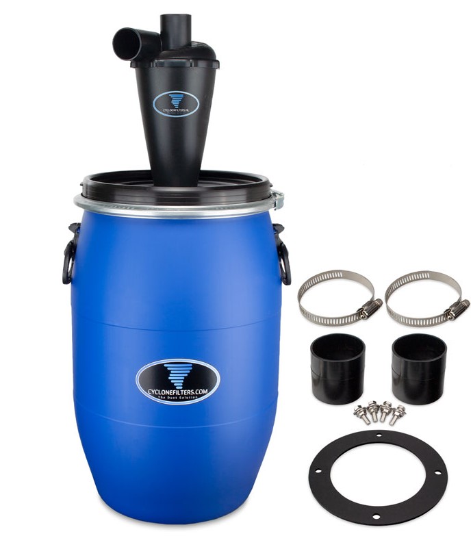
My idea is to hang a vacuum tube to the ceiling, so it can move around freely without being in my way. I would buy a cyclone filter and bucket, where I can hook up my vacuum cleaner.
If there´s some one with feedback related to this, please shout
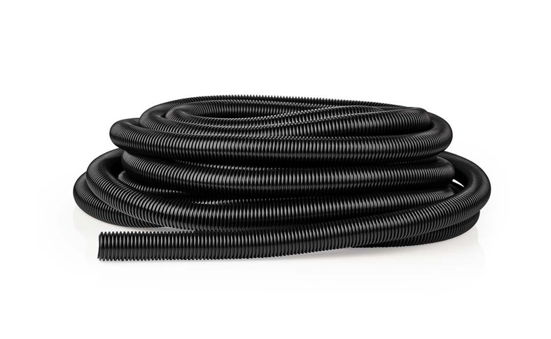
I am thinking to buy this tube, it is 15 meter long so will cover my needed distance to the ceiling, and has a diameter of 32mm which is I believe enough to fit Ryan´s design on the X plate.
As far as my understanding goes, it´s all a fit, although I will probably need an adapter on the cyclone to fit the tubes.
The big question will be if my vacuum cleaner will be powerful enough:)
I´m still doubting, but will probably order it this weekend, so I feel like a little kid now
Thanks for mentioning this!
I was already skeptical on using a plastic version, although mine is only 1000watt, maybe I should spend a little more and go for the metal one.
What is your opinion in size? Would 30 liters be enough, or better double up to 60?
So, just FYI @jeffeb3, you were right about the dog bones effect.
I tried again and this problem is eliminated (but got another instead )
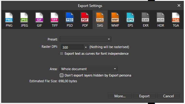
What I did was making a design in Affinty Designer, exported the design to SVG with the option to convert text to path checked on. I opened Photopedea and imported this SVG, and simply re-saved it to dxf.
When opening in Estlcam it imported just fine. Running the job with pocket hole there are no more dog bones.
A new strange issue I experienced, is that one letter got much more fatter then designed. I might have made a mistake in Estlcam although the simulation showed exactly my design.
Will post some pictures tomorrow as it’s late and I am getting tired after waiting one hour to see just 3 letters milled :s
So I figured it out, this issue was cause because for some letters I created an island and got confused with inside/outside milling
But I seem to have a workflow issue. Maybe some experienced miller can help me out:P
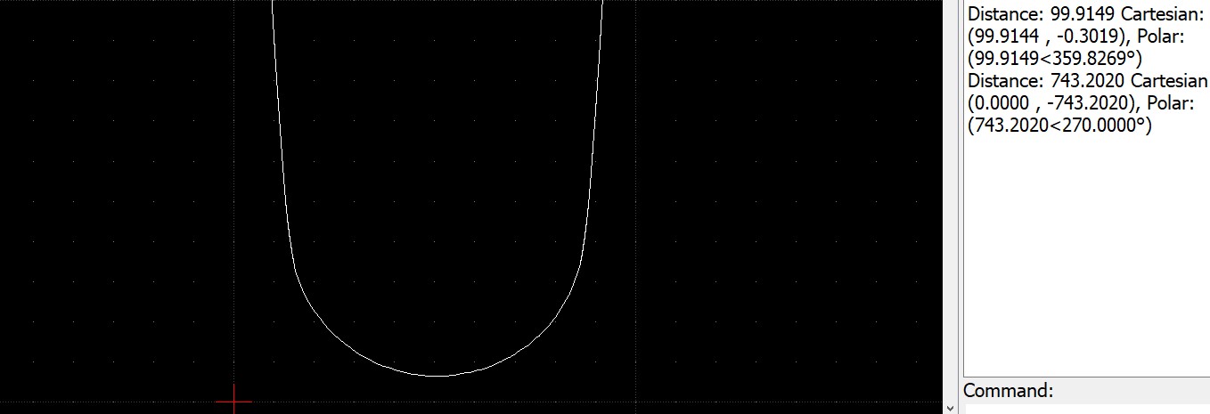
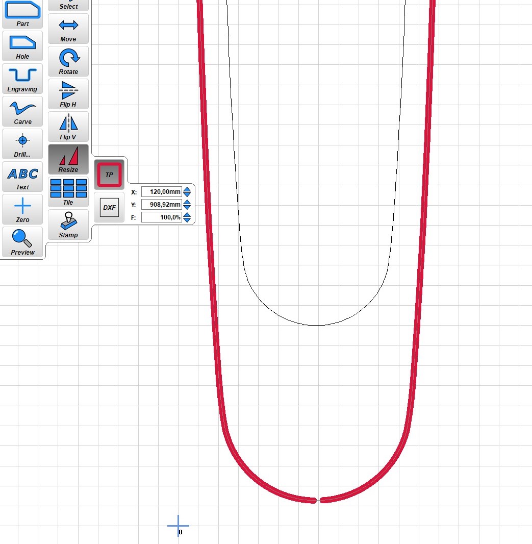
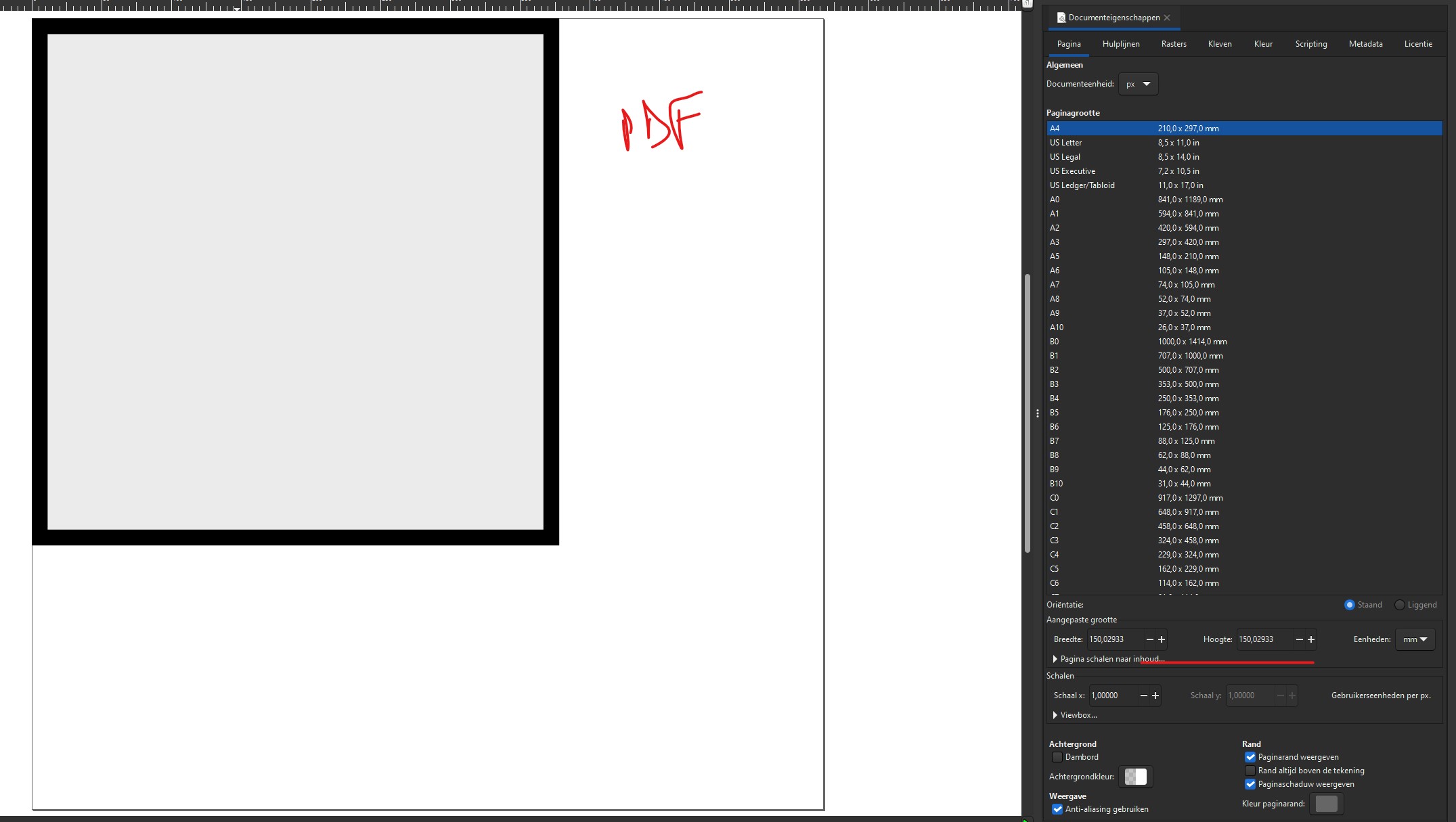
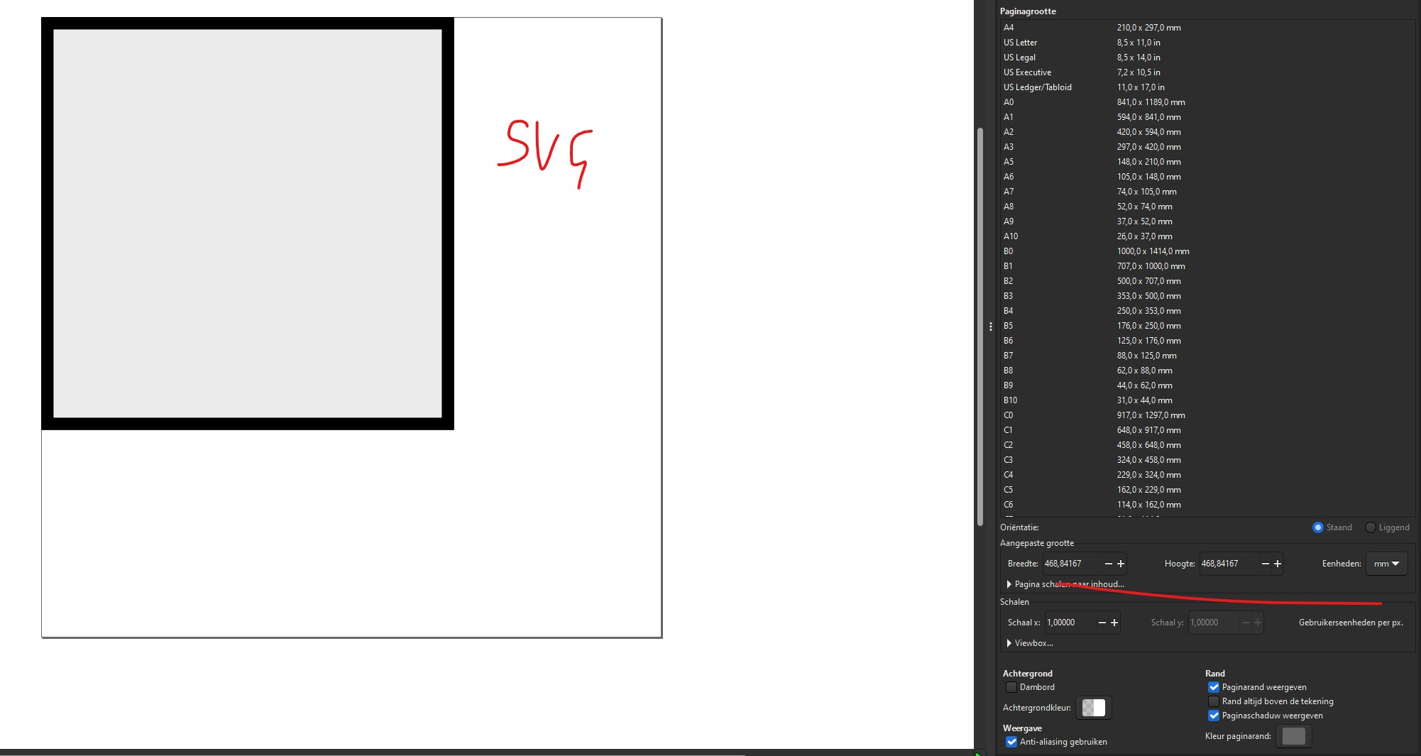
My practical issue is, that my design isn´t keeping its size when milling.
So what I did was;
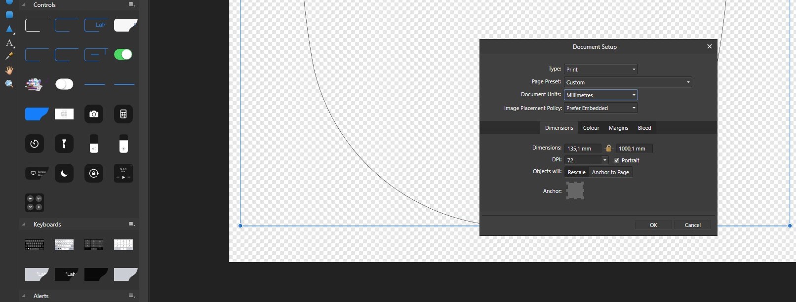
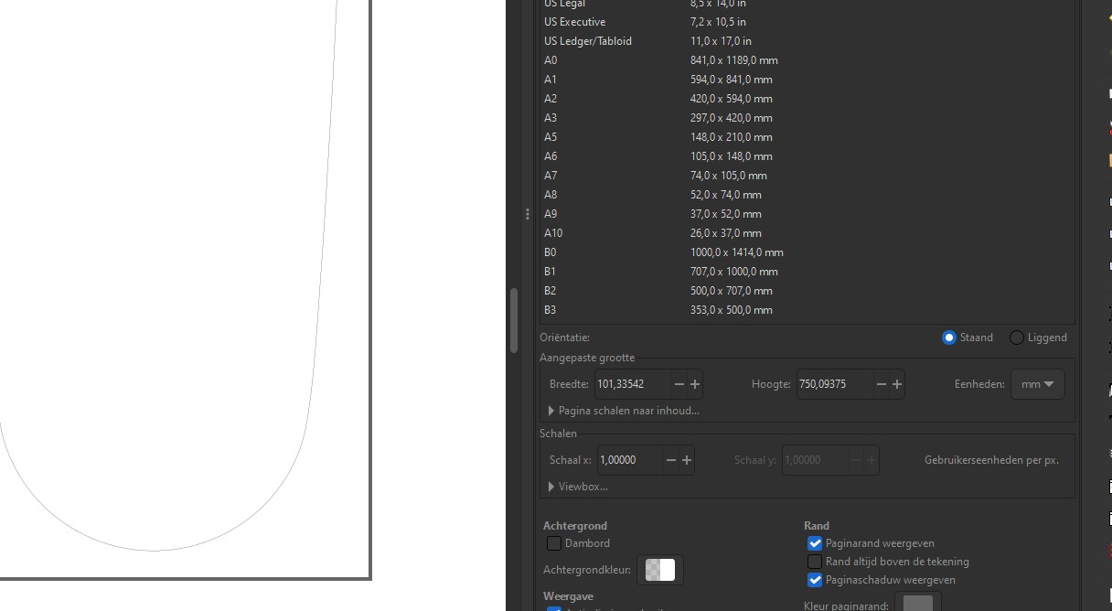
Create a 1:1 design in Designer 135x1000 (maximum workarea of the wood);
But when starting to mill it came outway bigger (± 150x1400)
I know I should use a CAD tool, but I´m no great artist in CAD and for my simple jobs I expect any designer tool would be enough. But how would one go from 1:1 design to an exact match in Estlcam?
And could it be that there is a bug in Estlcam?
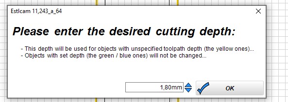
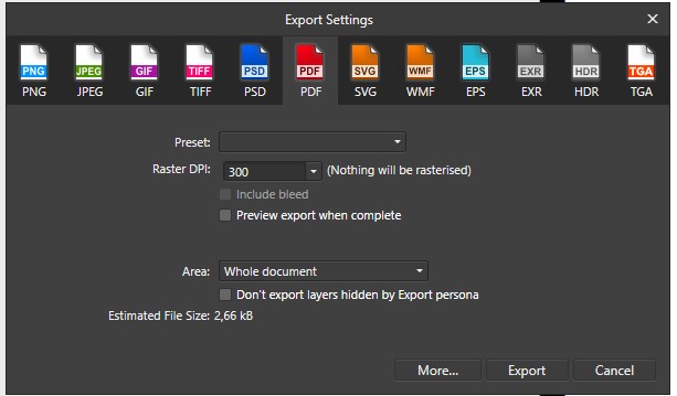
On saving I get the following screen, shouldn´t that be in cm? Like 1,8cm?
With this specific setting, the job only went 5mm in to the workpiece. Making me go complete nuts and confused
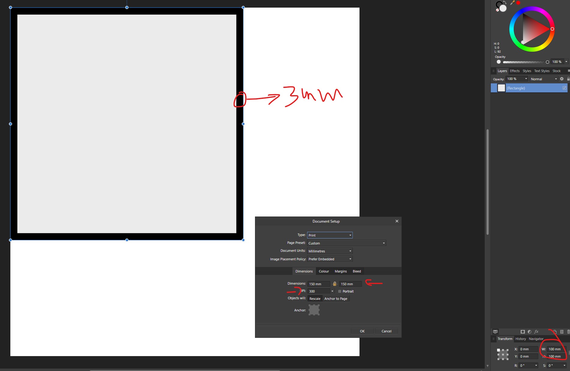
I am not really sure but I remember a few having issues. I think it has to do with your DPI settings.
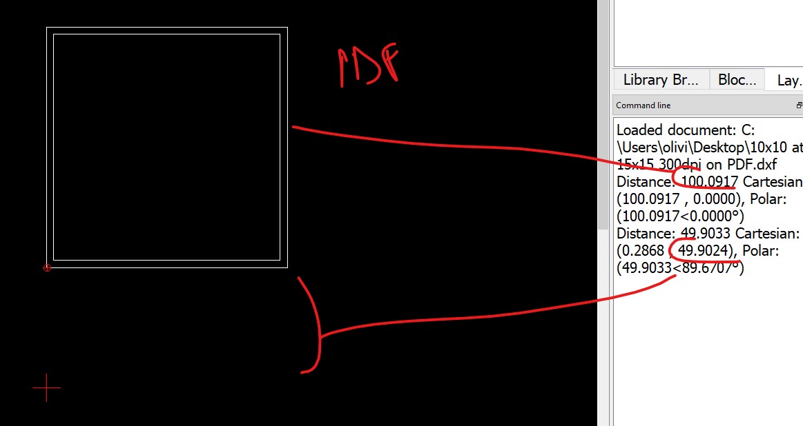
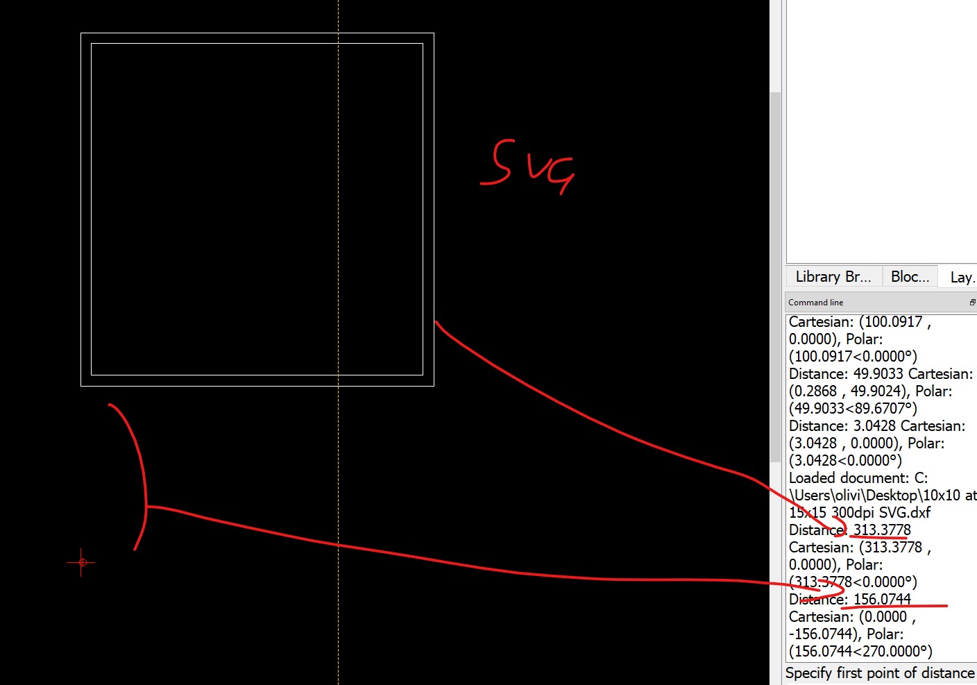
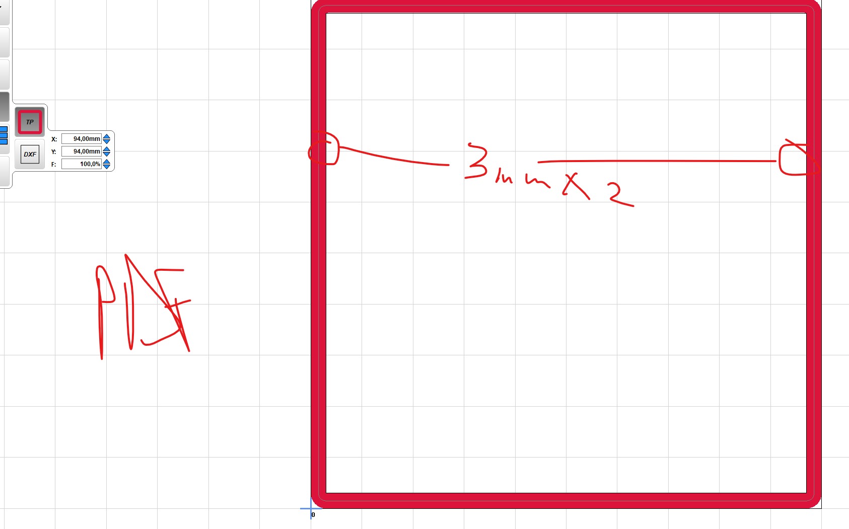
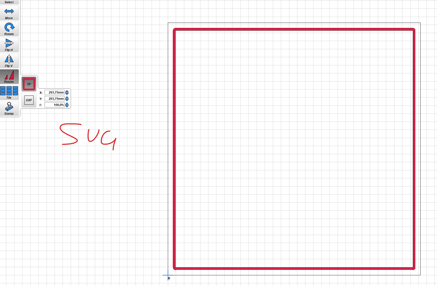
An really easy way to experiment is make a 100mmx100mm box export your SVG and set your estlcam grid to 100x100. You will easily be able to adjust the dpi (I think) to get it right. Yours shows 72dpi, for some reason I know inkscape changed at one point from that to 92 or 96 and it was an issue.
Conclusion is that Inkscape messes up the SVG file.
Also important to note, is that one need to stroke on the correct side of the lines, take into account the bit thickness, and the fact that the offset in the original design gets lost during export to dxf (no idea if that´s always the case).
My lesson learned is either stop using SVG, of use a CAD program, or search another tool then Inkscape.
You need to change stokes to paths, you are going to confuse the heck out of yourself trying to keep track off offsets and finishing passes, changing bit sizes.
But really at this point you have proven you easily have the computer experience to learn CAD quickly, you are easily doing all the 2D stuff as it is.
FWIW
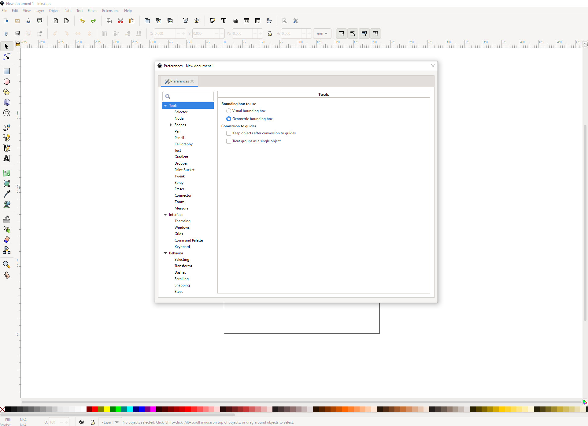
The first setting I change in Inkscape is:
Preferences → Tools → “Bounding Box to use” = “Geometric Bounding box”
This makes it so that the width of the stroke doesn’t impact the sizing of the object. Otherwise the stroke changes the exported and measured size.
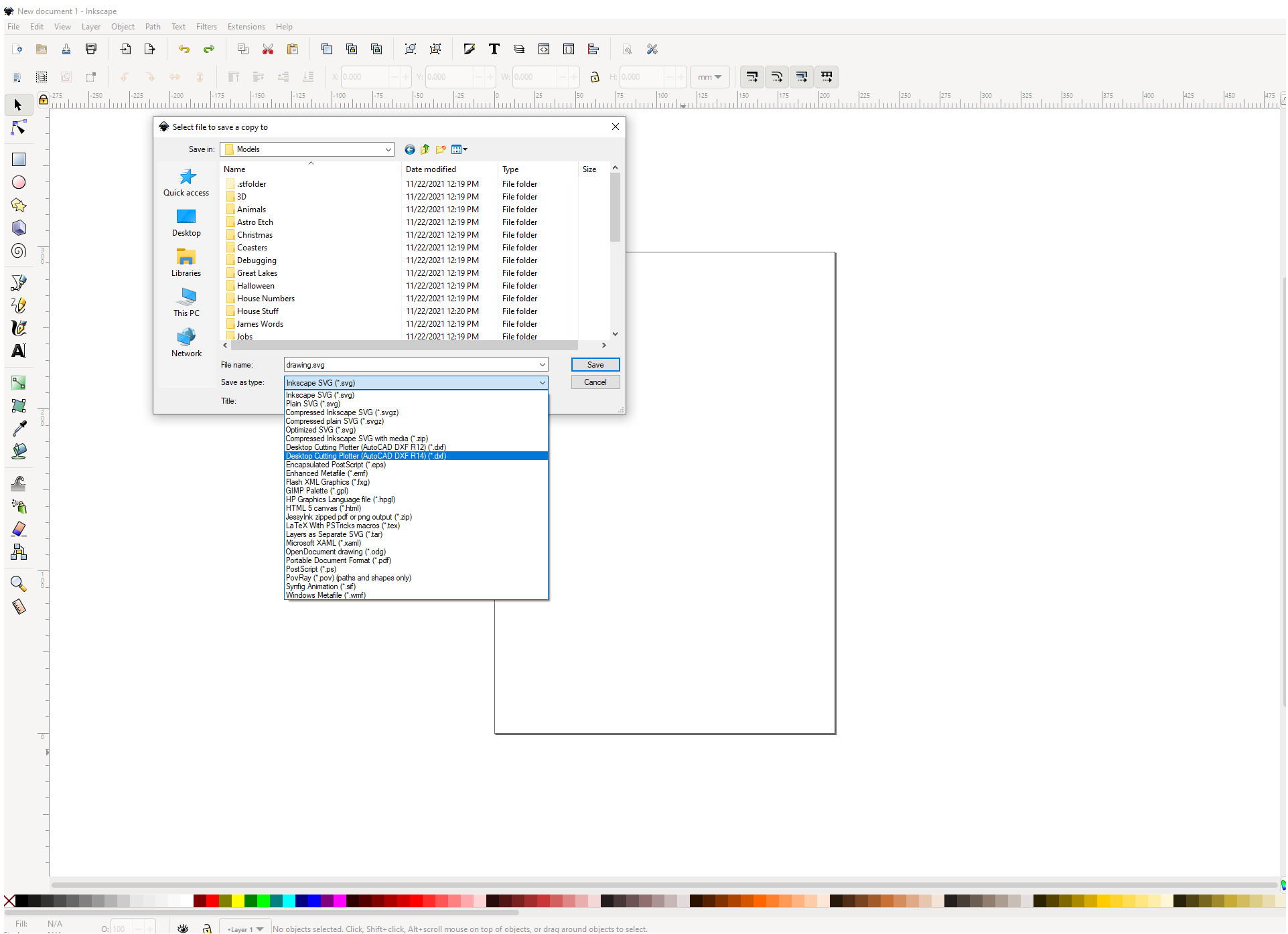
Then…I always save a copy of my file as a dxf to use in Estlcam. svg’s haven’t been reliable but dxf’s seem rock solid (make sure you convert objects to paths though).
Thanks for this thread - it’s about half an hour in front of where I am, and all this talk of svg and paths is a bit frightening! In a week or three we will see how much I think I’ve learned from it!
I am wondering if I actually need Inkscape? I am reasonably proficient in OnShape, and if I use Kiri-moto perhaps I can just get them to talk to one another? That will be an issue if I want to use graphics or lettering I suppose, as OnShape doesn’t really do that simply.

 In a week or three we will see how much I think I’ve learned from it!