This seriously did my head in. I’ve mentioned before that I know almost nothing about this stuff. I am quite anxious not to make a mistake and although my profile says I’ve spent a day reading these forums, the real number is more like MONTHS if counting the time lurking not logged in.
Therefore, I’m inclined to check first - move later. NOTE - I’ve tested my machine and have movement to all steppers - IT LIVES! So the following question is for my education only.
After I’d figured it out, I still don’t quite get why it works, so if someone can explain in words of single syllables I’d appreciate it. Something like “you are wrong” would be reassuring.
Here is the wiring diagram from Wiring The Steppers - V1 Engineering Documentation with the supplied loom. Note the hand drawn sketch on the instruction page matches this diagram, but the photo there (which was my clue) has the “Winding 2” connections reversed. I had tried all manner of flipping plugs and so on, but hadn’t consider the two windings as separate entities. Once I got my head around the reversal of the second winding wire I could see that there was at least continuity there, but how does that work if the current is flowing in reverse, and is the drawing still correct?
Thanks Jeff, now that’s about as clear as mud! I get it, but hope there’s no exam later.
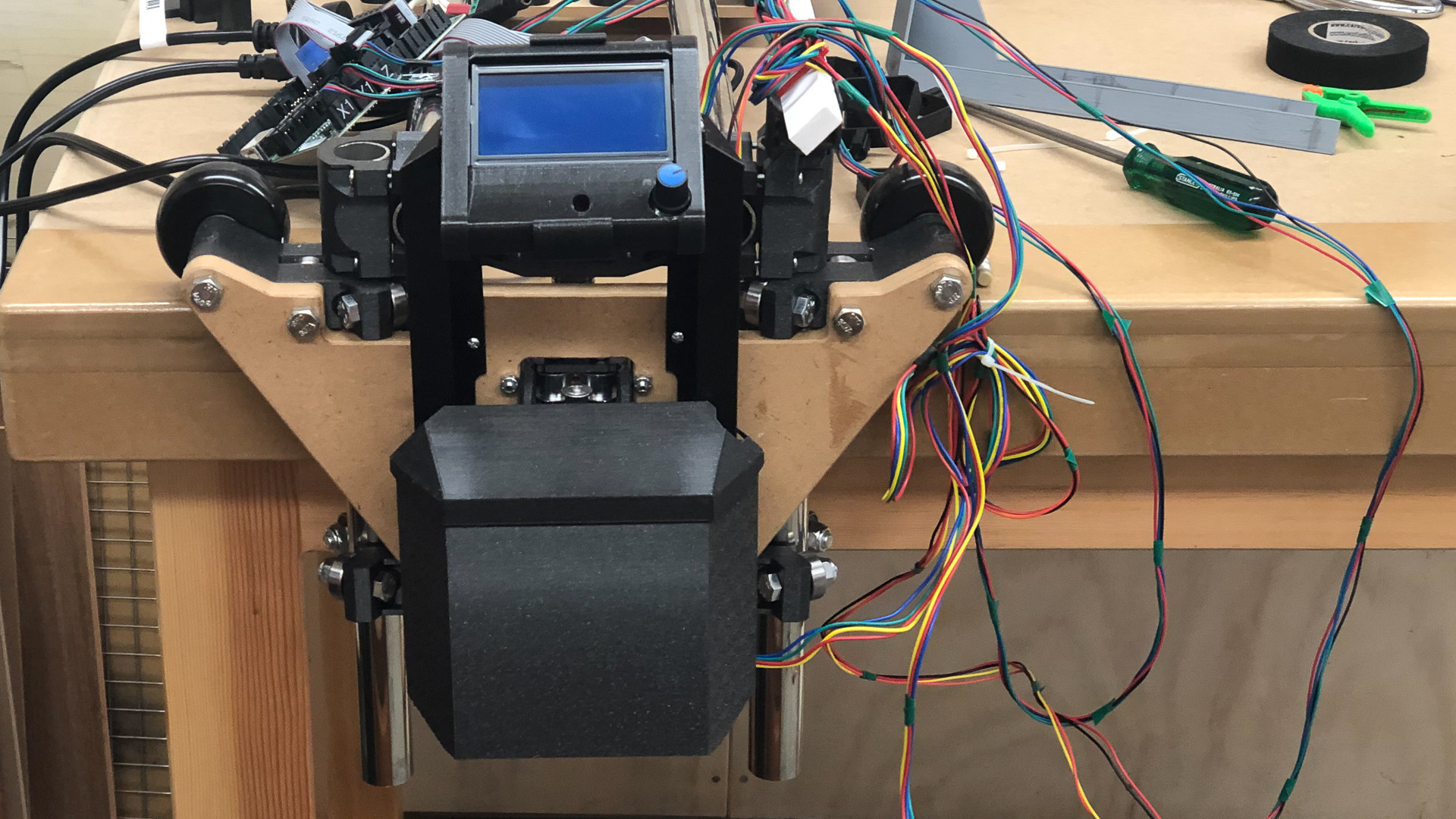
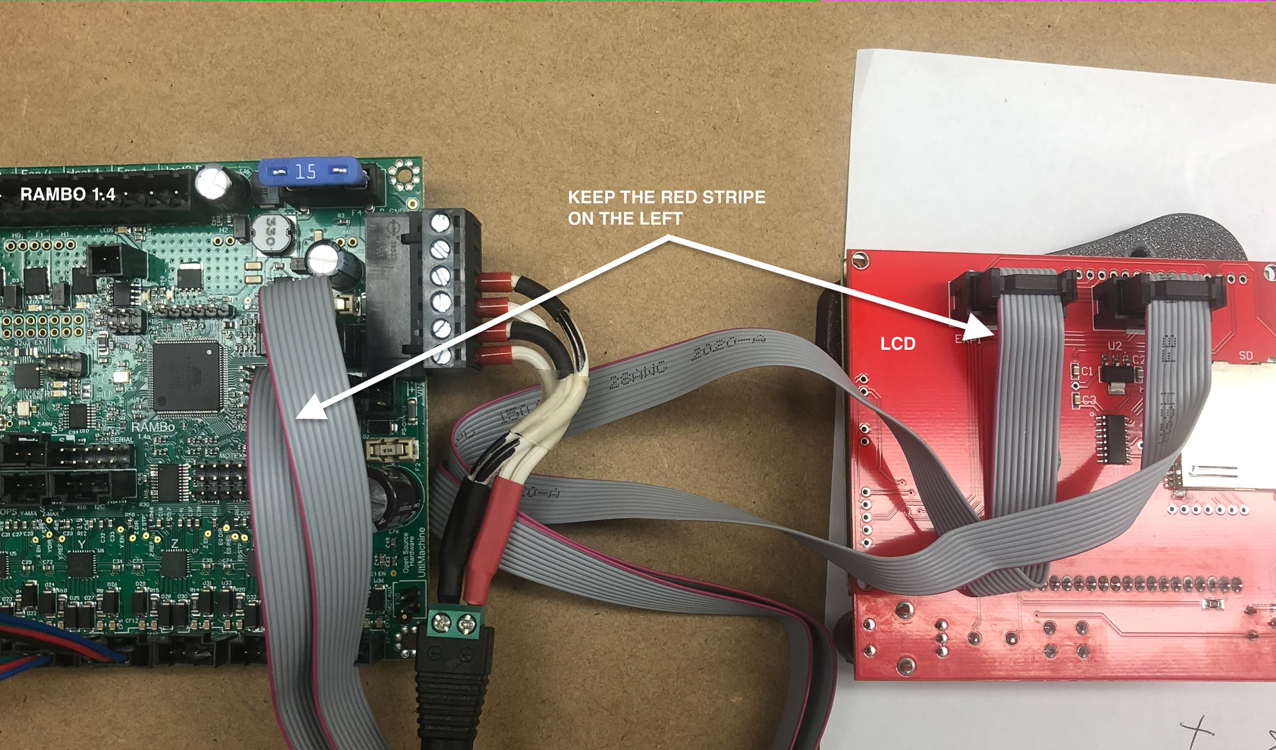
One of the things that seems to take a bit of finding is the correct connections to the LCD screen. I’ve posted this pic on another thread today but am burying it here in case anyone with a “blank LCD” stumbles across it in future.
While I’m here - why does everyone seem to keep that power adapter rather than snipping it off and hard wiring it in? I’ve made the little jumper for now, but that’s one thing on a growing list of changes to be made.
I’ve pretty much spent the whole day peering through the understandascope.
I now have - Repetier working on the Mac, but can’t find any of my USB C to A adaptors which means I can’t plug in the cord from Powerbook to Rambo. I have a sneaking suspicion that they are all on the boat, which has been locked in a shed in Belgium for a couple of years, and since we have been locked in Aus for a similar time, I think I’d better buy some more! Doh!
I have Kiri-Moto working too. It’s not Estl-cam I know and that will put me behind the 8 ball when the inevitable questions arise, but I could buy some commercial software for the price of Windows and an emulator (which I am quite tempted to do). For now this all seems to work in theory anyway.
I don’t have any belts on the machine - but all the steppers work and I think they are even in synch and moving in the right direction.
I’m just enjoying fiddling at the moment, so don’t expect a crown any time soon, but anything can happen.
What happens to the power cables (spindle and board) - do they just hang in a bit of a loop below the table?
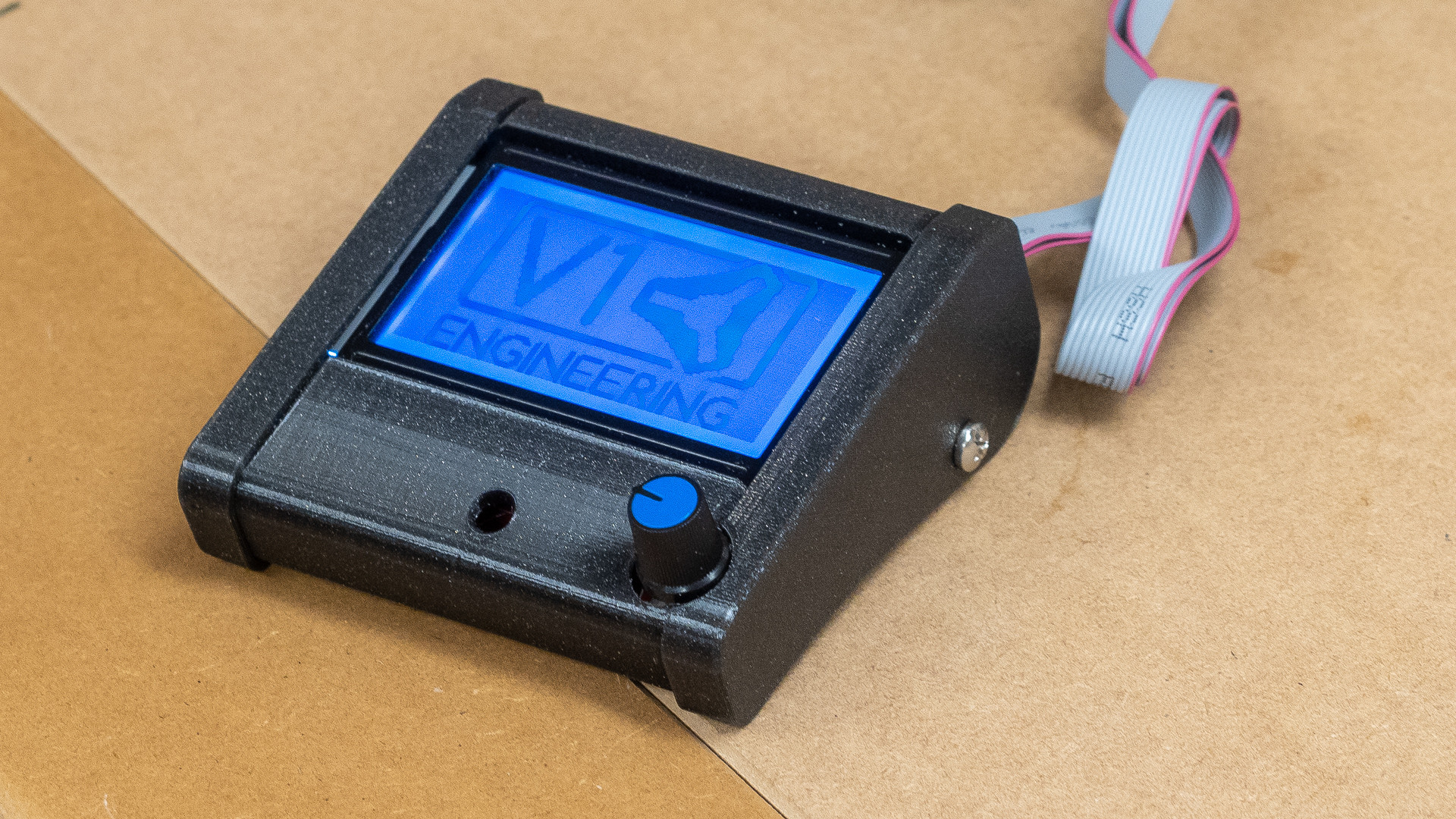
Finally - I have the LCD in Ryans’s @vicious1 case, it did take a little bit of fettling round the knob to get proper clearance, but it’s a lovely bit of design-for-purpose.
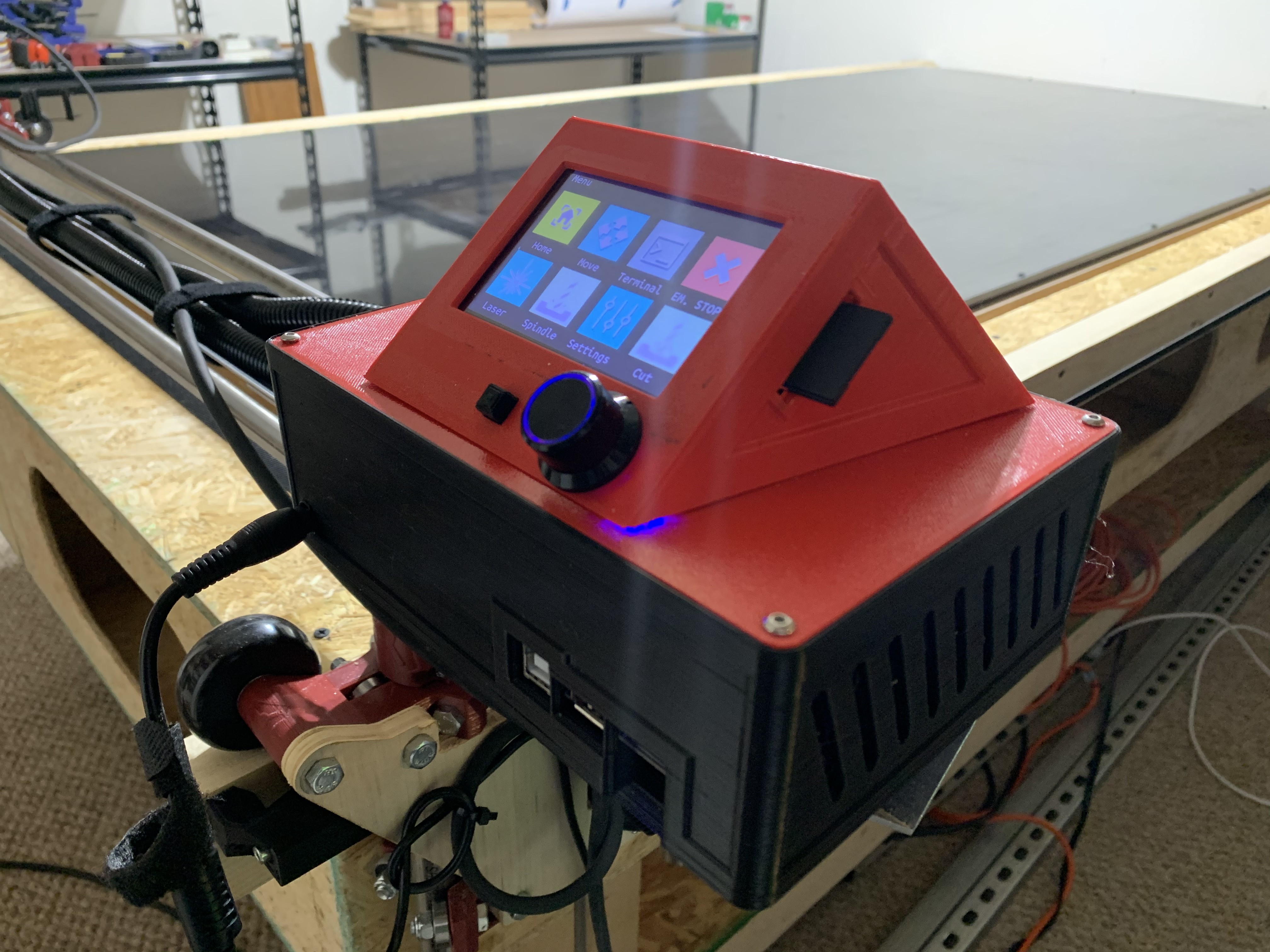
I not only kept the power adapter plug but am glad I did. I made a remix of the 3D-printed case that was suggested here on the site (for the type of board I have, a BigTreeTech SKR Pro 1.2 with a touchscreen that is a BigTreeTech TFT3.5 E3) and one of my mods in the remix was to make a little “sled” inside the case for holding the bit that takes the power adapter barrel on one side and takes 2 raw wires screwed down on the other side. That sled holds the piece facing a hole that lets me plug / unplug the unit to power it. Because the power cord is (not far from there) zip tied to the setup, when I need to power on the unit I grab the dangling cord and plug it in. I was in a hurry to get mine built and get a job done, and so, short of installing a switch, this gives me a handy way to on/off the thing.
Thanks for that, I did briefly consider doing something similar, and one day I might, but for now I’m trying to keep the whole setup “stock” or as near to it as my ever fidgiting brain will allow! There are a lot of details coming up that will stop me from getting it working if I spend any time thinking about them, so I have to keep my eye on the end game!
What is your table surface? Presumably you are using it for cutting vinyl?
My kit is all stock. The BTT SKR and BTT TFT are a kit choice on the V1 order page (instead of RAMBO). Regardless of what board and touchscreen you have, you will want a case in place to put them in.
Re. Table
I had had to build my table out of OSB. Above that is a spoil-board of MDF, and above that is half-inch sheet of HDPE black plastic that is ready to be cut for a job.
I’m hampered at the moment by a bit of a heavy sinus infection which seems to have turned my brain to mush, so instead of cracking on with a few projects I’m trying to think a bit ahead here.
I haven’t really considered what spindle options I have in the long term - I have a Ryobi 400w trim router, which buzzes happily at 29000 rpm apparently, and I was going to use that as a proof of concept sort of thing. I know there are many other builds that have used similar quite successfully, but from the little knowledge I have retained on this subject that might be a bit speedy for many uses.
My observation is that the Makita 710 seems to be the new default in places where the De Walt is not available, so I’m very inclined just to spend ANOTHER $290 and build that in from the start.
OR for a similar amount of money, should I just “invest” in a 400w spindle with 3-13000 rpm electronic controls, proper collets etc etc.
Yep, you are all going to ask “What do you want to do with it”, and I’m afraid I’m going to reply that I have no clue - learning the CNC process is the next step!
If I could conduct a poll I would: Ryobi 400W (free), Makita (700w router) or Spindle 400w?
I have the Makita, and it has a knob that permits variable speed control. Seems to be working great.
Variable speed is pretty important. Whether it’s manually done like the knob on my Makita, or controlled by software, either way, you really will want variable speed.
After a few days of staring at the ceiling - head too unclear to work with either woodworking machinery or things that might go zap, I decided to fix a problem that doesn’t exist.
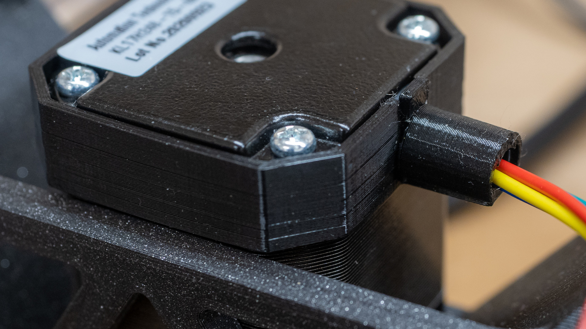
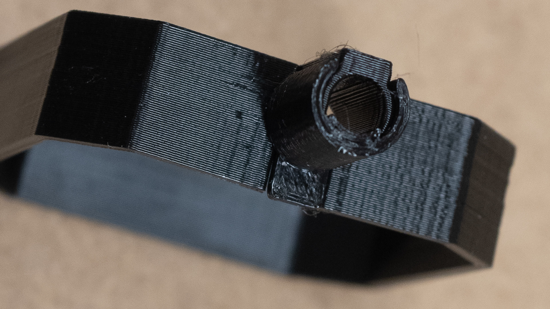
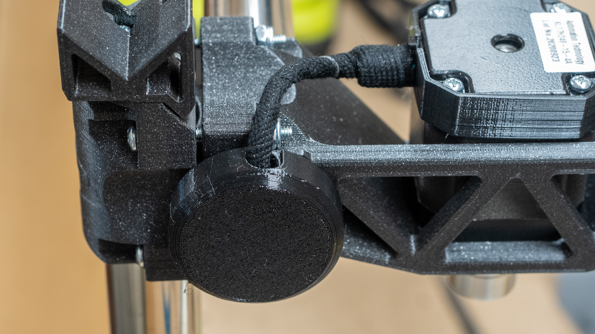
I’ve never liked the lack of strain relief on stepper wires. This may not cause an issue at all, but it just looks as though it will, and I find that little bit of naked wire between loom and stepper oh so jarring! So I drew a solution to allow cable covers to tie more securely, which looked so similar to this one: http://www.thingiverse.com/thing:3650033 , that in the end I just re-drew it a lot lighter as a bit of a printing challenge. (will eventually upload the STL in case there’s another print masochist in the world).
So here we are - 1mm wall thickness, PETG, 0.2mm layers, .4mm nozzle - drawn with zero tolerance between the two parts. Now I’m wondering what I could do with .05mm layers and a .25 nozzle… hmmm.
I don’t expect that heat will be an issue, but if it is, the melting PLA bits the motors are mounted to should warn me in plenty of advance warning. (Serious thoughts on that would be welcome.)
I love the way every day on this forum someone just bobs up with a first post showing their complete build and a bunch of things they’ve made. I am not one of those people.
Today’s angst is brought to you by - “let’s reinvent how to mount the board”.
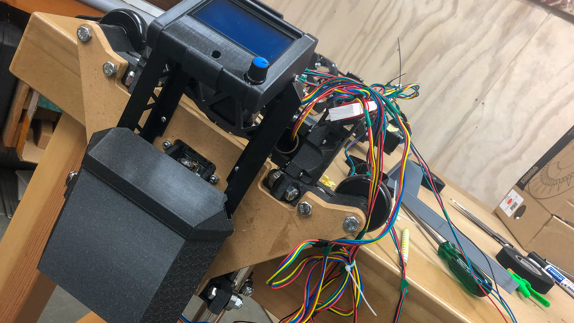
I like Ryan’s @vicious1 Gnarly case, and I’ve already posted pics of the lcd case, and all it should have taken was a bit of timber packing a few screws and it should have been mounted. I also think the “wings” of those end plates on the LR2 pretty much defines the design, and think it’s a pity to cover them up with random boxes. Therefore in the spirit of “I’m not going to reinvent the wheel, or overthink this”, here’s my new wheel.
I redrew Ryan’s clip for the LCD screen, and used two trussed standoffs angled to match the sides of the case. Access for the USB point will be under the lid of the case. It’s a prototype, but it’ll probably be there for a while.
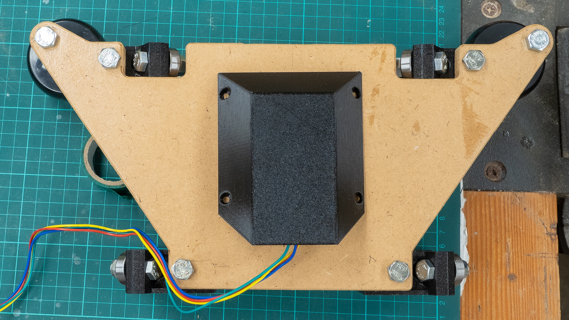
I’m not sure just how free the centre assembly has to be - it runs very smoothly but it needs light pressure to move it - a gentle flick will move it a foot or two, not send it flying out of control. I’ve used every trick I know to align the brackets, if the consensus is that they need to be really free, I can drill the mounting holes a little more oversize and slightly spread the foot of each x roller before tightening it.
Perhaps it’s something that a little weight will improve?
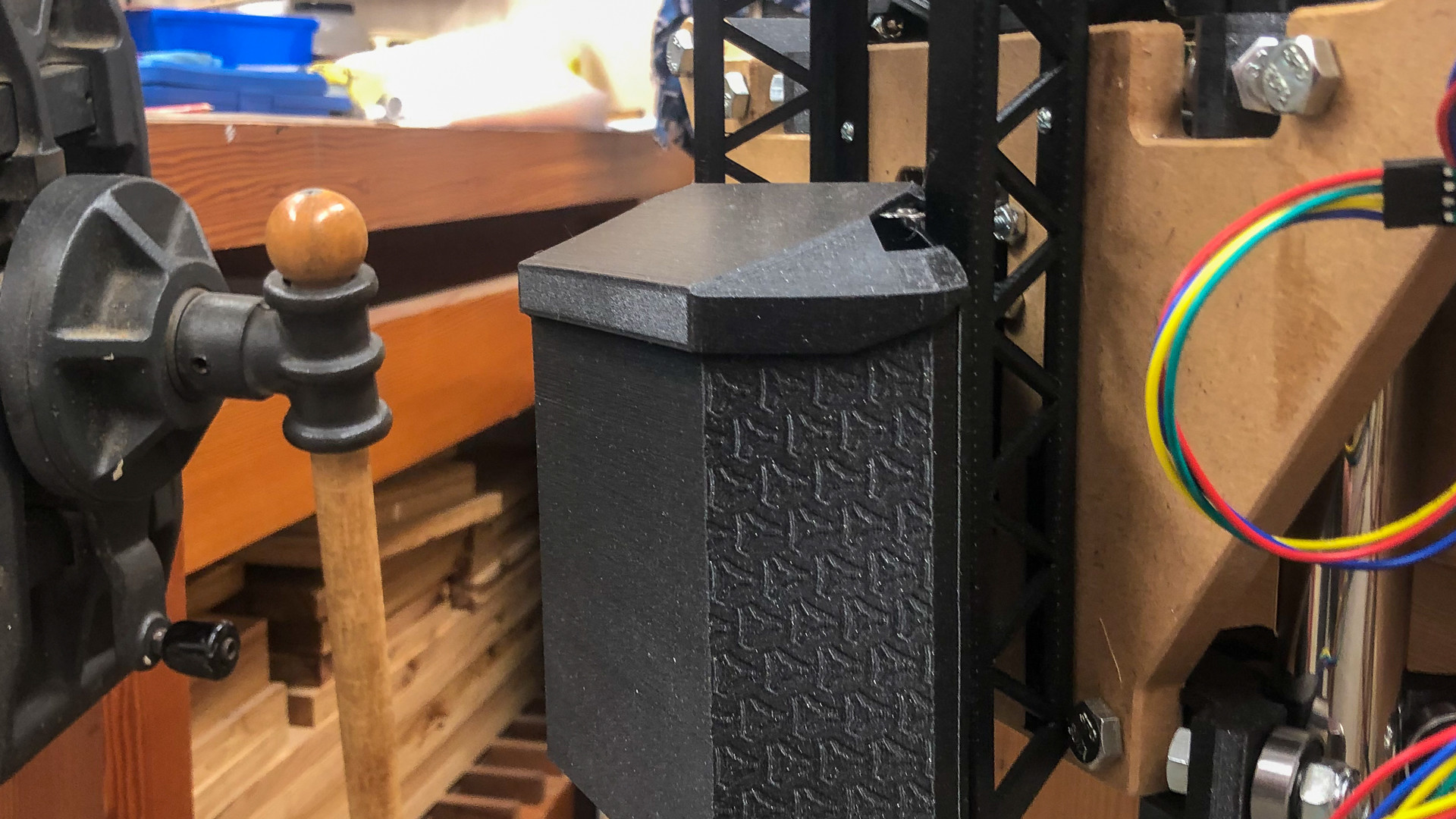
On another note - inspired by the Gnarly case, I thought I’d pop out a cover for the stepper. As much as I like the shape of the plate, I’ve never been in love with the exposed belt. Too much do you think? I can shrink it quite a bit in the final version.
It should keep little fingers fingers out, not that they’ll be there when it’s running. No it’s not square, but it will be - just waiting for some printing supplies to arrive from the other side of the world.
On another note - by way of delaying completion still further so I don’t have to address the looming “gcode-and-all-things-to-do-with-making-this-actually-work-lack-of-knowledge-crisis”, I’ve been fiddling on completely unimportant things at the end of the spectrum I do understand. Perhaps jealous too, of everyone who just seems to be able to get on with it.
I may never get the thing going, but it will be a nice ornament. Have I gone too far this time?
Thanks Jeff, I can and I will! (but that doesn’t mean I can’t muck around putting it off for as long as possible! It was less than twelve months ago I was in the same muddle with the mysteries of CAD and 3d printing, and I managed that even without the incredible support that you blokes round here provide!
 So the following question is for my education only.
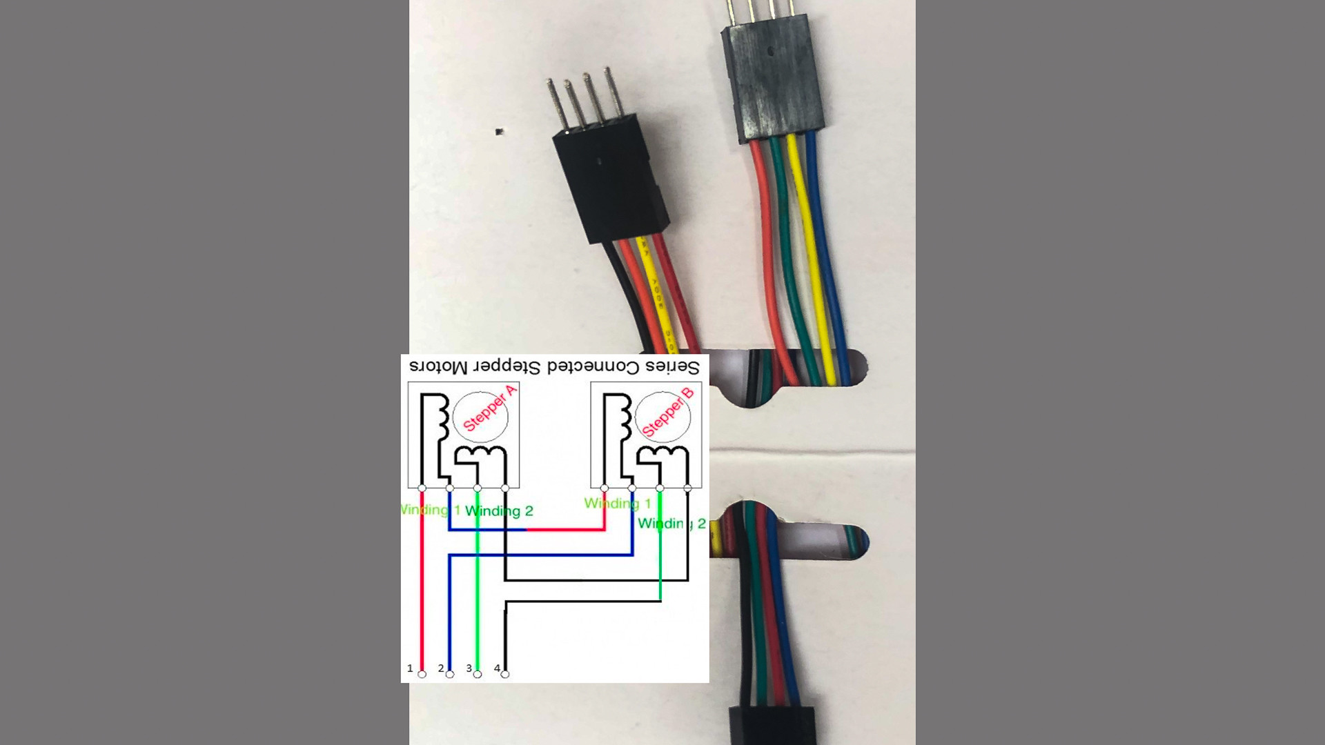
 So I drew a solution to allow cable covers to tie more securely, which looked so similar to this one: