Hi guys, I’m trying to build the lowrider2, as configuration I am using shield ramps 1.4, drv8825 x5 a tft screen and dual endstop firmware for ramps of course, but I haven’t done the electrical connections yet because I can’t find a guide anymore detailed, has anyone already done it? Is there a more specific guide with this combination? I saw that for skr pro there is a lot of stuff but very little for ramps.
https://docs.v1engineering.com/electronics/ramps/
The ramps board and drivers have shown severe quality issues, so they are getting used less and less. Some of this info might be outdated, we stopped using them 4 years ago, but the connections are the same.
I have your same configuration (but with the reprap full display).
Since you have the firmware set to use the double Y and the double Z driver basically you have only to wire the endstops.
Here: https://docs.v1engineering.com/electronics/dual-lr/
Don’t be scare to check everything with M119.
Yes, the quality of my ramps board is really low and actually I never saw a good ramps out there. I definitely wouldn’t trust a ramps if I had to use an hotend or a bed heater.
2 Likes
Grazie per i consigli, proveró questo cablaggio, e nel frattempo mi procuro skr, se come dice Ryan ci sono problemi di qualità usare skr é d’obbligo direi…
1 Like
La SKR e` anche soluzione piu` economica direi.
Non capisco il senso di avere una board a 32 bit su una cnc a 3 assi, pero` e` un problema mio questo  .
.
The SKR board is even the cheapest solution I guess.
I don’t get the point to use a 32 bit board on a 3axis cnc but this is just my opinion .
Il problema è che io ne capisco molto meno 
Umberto, non è che magari puoi postare una bella foto? Così almeno vado sicuro di collegare i cavi nel giusto verso
English Below
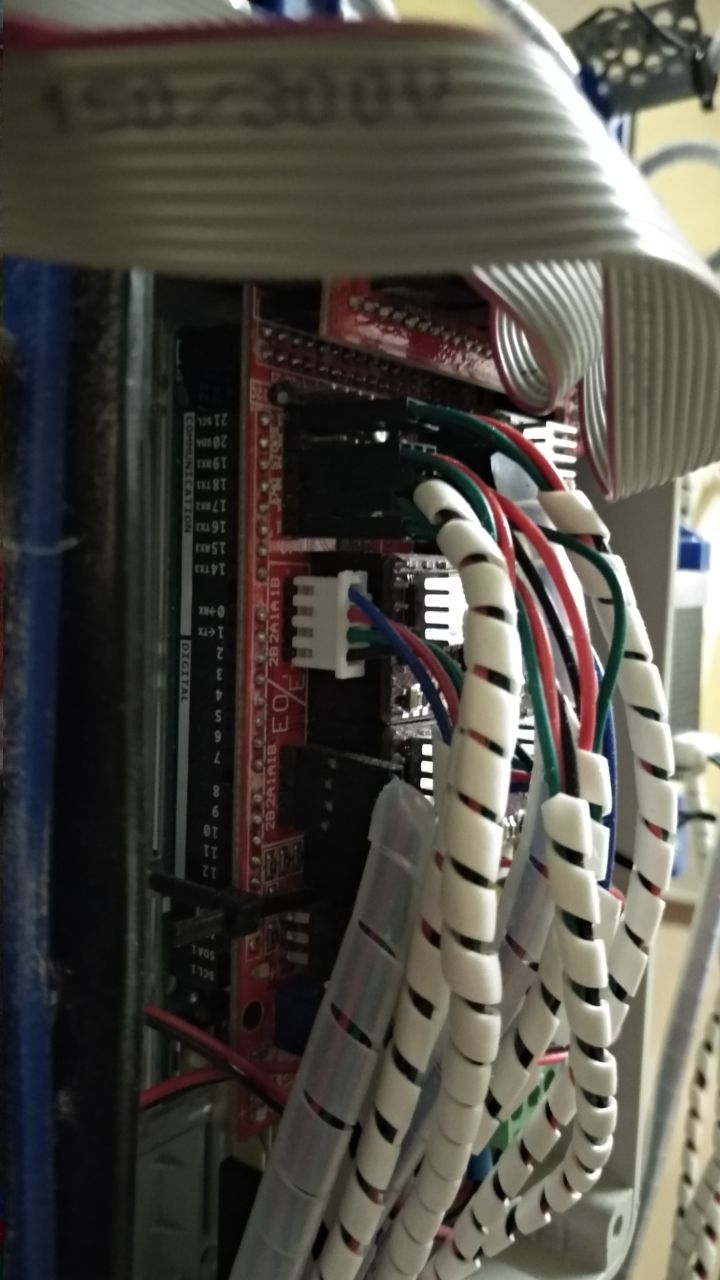
Ciao, ecco una foto della mia RAMPS. Non so cosa si possa capire 
Allego anche una foto presa da internet che evidenzia bene la posizione dei Pin di finecorsa.
Non e` complesso.
minX → finecorsa X
maxX → finecorsa Z2
minY → finecorsa Y1
maxY → finecorsa Y2
minZ → niente
maxZ → finecorsa Z1
Per collegarli usa SOLO i pin “S” e “-” dei ogni gruppo.
Al pin “S” collega il terminale NC del finecorsa.
Al pin “-” collega il C (comune) del finecorsa.
Controlla tutto con M119 da Pronterface o Repetier Host. Prova a cliccare a mano ogni finecorsa e verifica che lo stato sia corretto.
Dovresti leggere “TRIGGERED” quando il finecorsa e` premuto.
Hi, here a picture of my RAMPS. I don’t know what you can understand from it
I attach a picture from the internet that shows the position of each endstop.
It is not so complex.
minX → endstop X
maxX → endstop Z2
minY → endstop Y1
maxY → endstop Y2
minZ → nothing
maxZ → endstop Z1
Use only pins “S” and “-” of each group.
The “S” pin should be wired to the “NC” terminal of the endstop.
The “-” pin should be wired to the “C” terminal of the endstop.
Check with M119 from Pronterface or Repetier Host. Try to click each endstop and check the status.
You should read “TRIGGERED” when the endstop is activated.

Umberto