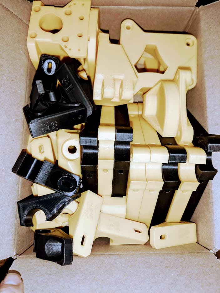
Off to a great start! Ordered a kit and thought to myself… I have just enough left on this spool for one piece.
![]()
Oh well, on to the next!
Off to a great start! Ordered a kit and thought to myself… I have just enough left on this spool for one piece.
![]()
Oh well, on to the next!
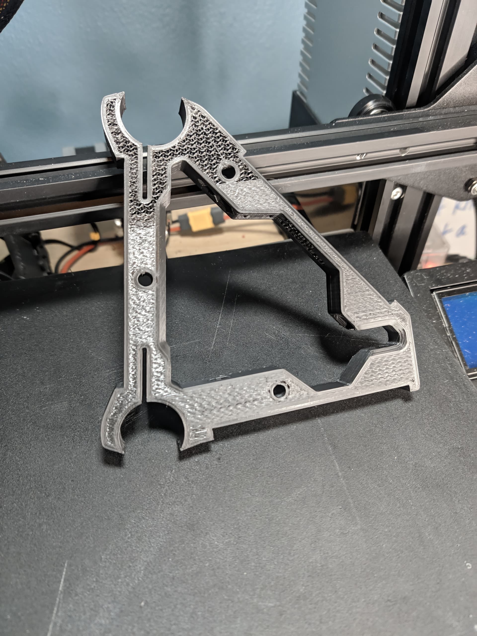
That was one of he 50% infill braces - took 4 times to get it printed! Second time was a layer shift I missed, third time I aborted early, but can’t remember why - probably adhesion. 4th time worked! Then I printed pretty much everything else without issues.
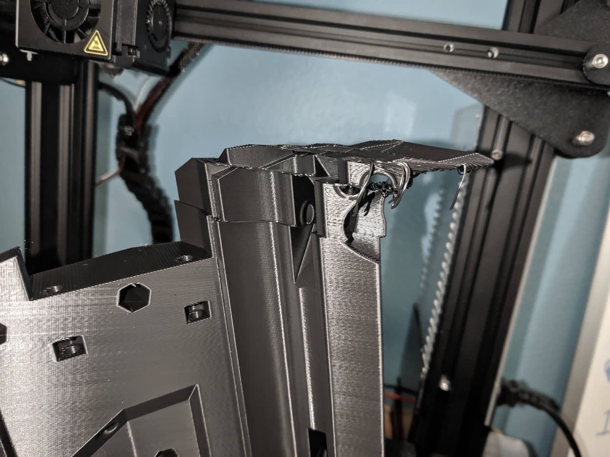
All the way until I get to the core… then this happens:
I had put tool holders on the top of my Ender 3 as a convenience to keep them close by. It has never been an issue because I don’t print big things… until now. It appears the wiring/Bowden tube caught on the tools and induced shifts.
I guess I just can’t print the “high infill” parts properly!
@vicious1 or @jeffeb3 - any patches available for the Keyboard-Chair interface? 
I’m getting excited to start assembly… I hear the “Vroom Vroom” stage is the next big milestone!
That is the issues with the tall pieces. Most rarely print them so things like this happen. Never knew you would need to constrain the bowden better. What a bummer.
I do have to say, even with the failure - it is the biggest thing I have ever printed and it turned out 90% great!
The design is definitely something to see printed… pictures don’t do it justice. Even after several years of a 3D printer - this amazes me that something can go from a digital file to a substantial part in my hand in less than a day. I’m just going to admire this one until my new filament comes in tomorrow!
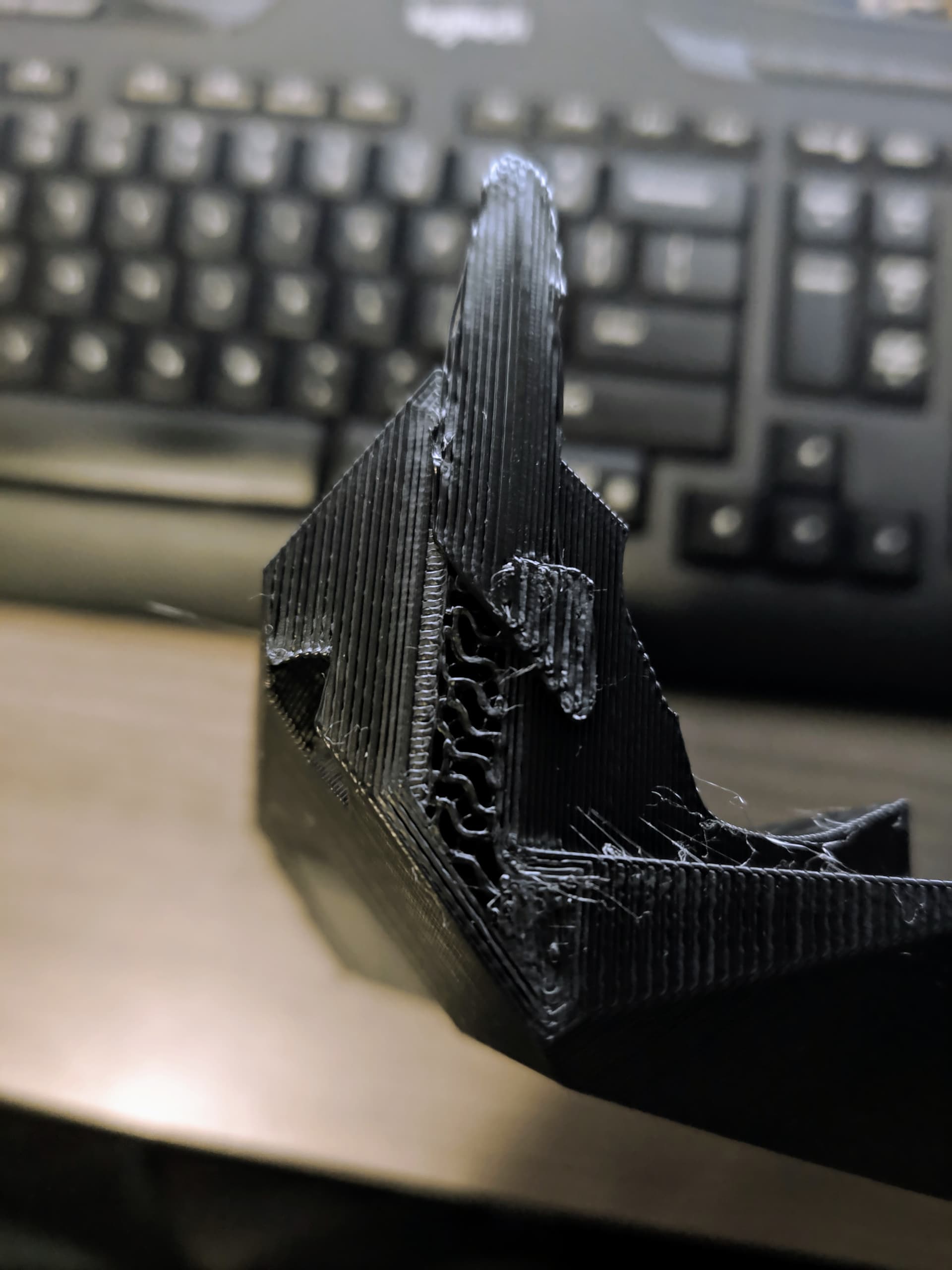
Just posting an update. My last one had this same layer shift with 8 layers left.
“Get a 3D Printer” they said “You can fix things around the house” they said. Nobody ever said I’d be fixing my 3D prints!
However, since this was above allt he mounting points and doesn’t appear to be a structural issue, I decided to work with this - if it bothers me, I can always replace.
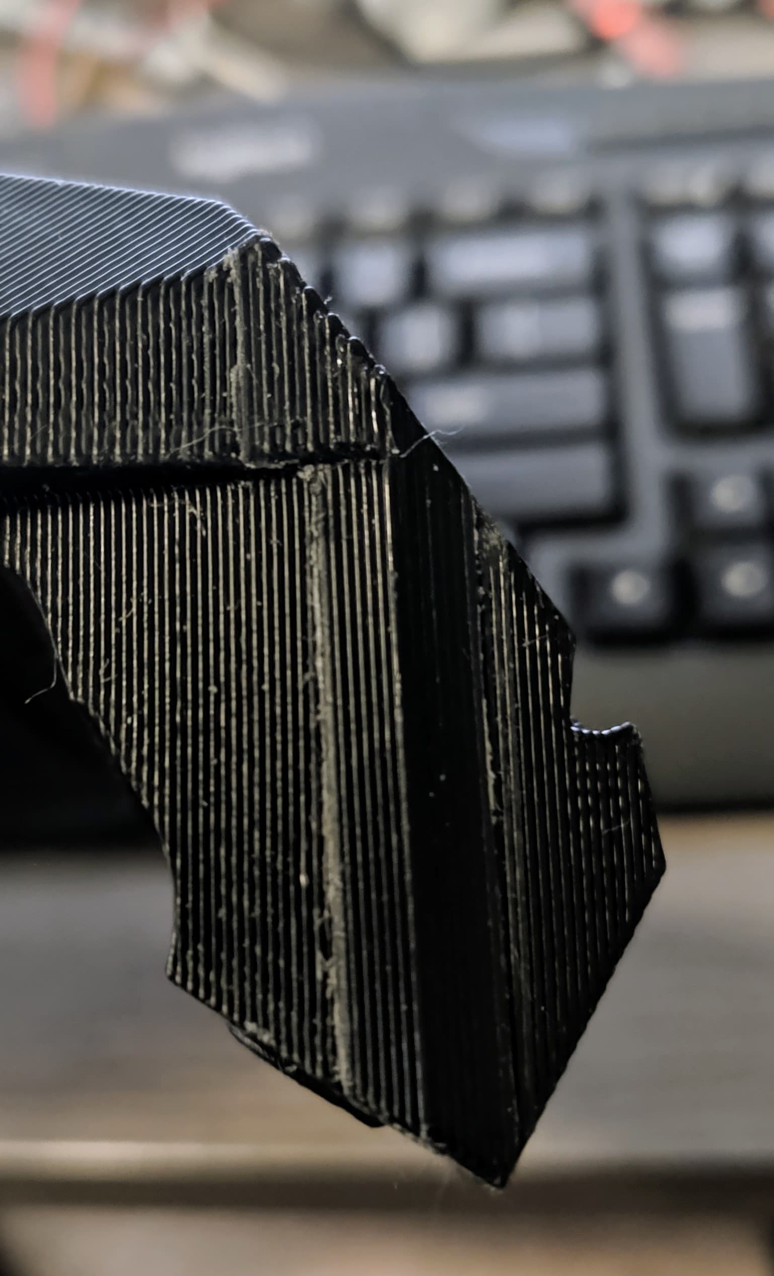
Fixed!
Just an 8 layer print and a bunch of Super Glue - but the infill is covered. (It was Loctite brand - although MUCH better labeled than their thread locker products!)
I did notice that I missed printing the Leadscrew Stubs since I have milled plates, so I’m waiting on those now. Other than that, assembly has gone really easily and smoothly. The instructions are very helpful.
Although because I don’t have threadlocker on hand - I will need to disassemble a bit to apply that when I pick it up - feel free to roast me later if I have troubleshooting issues with the grub screws! I am stopping now to go shopping, so hopefully that won’t happen!
I did have a question about endstop wiring as I assemble. As I forgot to add those to my order, I sourced them locally. Is there a recommended length for endstop/touchplate wires as I assemble? Are people generally making a little stub and then using extension cables like the motors, or using a direct run? I didn’t see an answer here:
As I have been building, I have been finding it easier to make a table of all the parts I will need for each step. I realize that it does make the instructions longer, but I could perhaps put all the tables in a collapsed section? If people would find that helpful, I can submit a pull request on the documentation.
Example:
@KL2001, I didn’t come across any recommendations. Just shared some info on what I did, what I learnt, and clips showing how I wired/built my LR3 @ Purple-black-rainbow LR3 🤷♂️ , build video @ https://youtu.be/FJ7nYio8oOE - #19 by azab2c hope that helps with your build!
As I’m looking at the Core wiring again, I’m trying to figure out how I want to handle a touchplate.
I see here, there is a Dupont connector - Do people then make a custom cable to plug in touchplates for easy swapping? Is this too complicated and it works better to just hardwire it?
.jpg)
After that picture, I actually just put the actual touch plate wire in there from the kit. I was looking at it today, a plug might have been cool. I use it a lot but have not come up with anything else.
Work has been busy, but I’m back at it and am on the gantry/screen wiring. Do people generally lengthen the screen wires, or just use the screen sitting on the gantry/electronics box? I’m thinking it might be nice to have it as a short pendant, especially if I read the new firmware update that allows the touchscreen to work more reliably for jogging.
I don’t move mine off the top very often. I am about to offer a wireless option if you are interested. Search for “headless” to join that discussion.
If you mean this one: Headless SKR Pro Info
I have been following along.
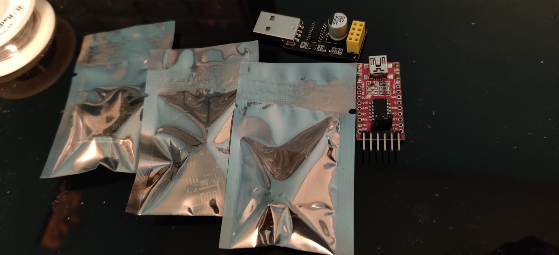
Over at the electronic bench, I’m ready!
I bought a half dozen esp01 boards from AliExpress a few years ago. I also have 3 D1 minis on hand, but the pin out won’t match, even if they offer more flash space.
Sweet!
I’m back at it and working on electronics. I’m looking at this picture:
.jpg)
I can’t seem to figure out the LCD cable. No matter how I route them they seem to be too short to have the knob within reach. Is this just a case of Ryan being able to route wires like he packs shipping boxes - magically?
I have a feeling this might be one of the first areas I change, but wanted to build it “stock” to learn before changing it. Perhaps in conjunction with a wireless addition.
Other than that, I desoldered the homing pins, and powered the board up. everything seems to work electrically, next step is to wire it to the motors and switches, and find a place to set this all up for testing - I could no longer utilize the living room.
Excited to get this finished by spring and then I can move it to the garage and try some larger projects.
I have it turned 90 degress now facing forward. I could not get the extra long LCD cables anymore.
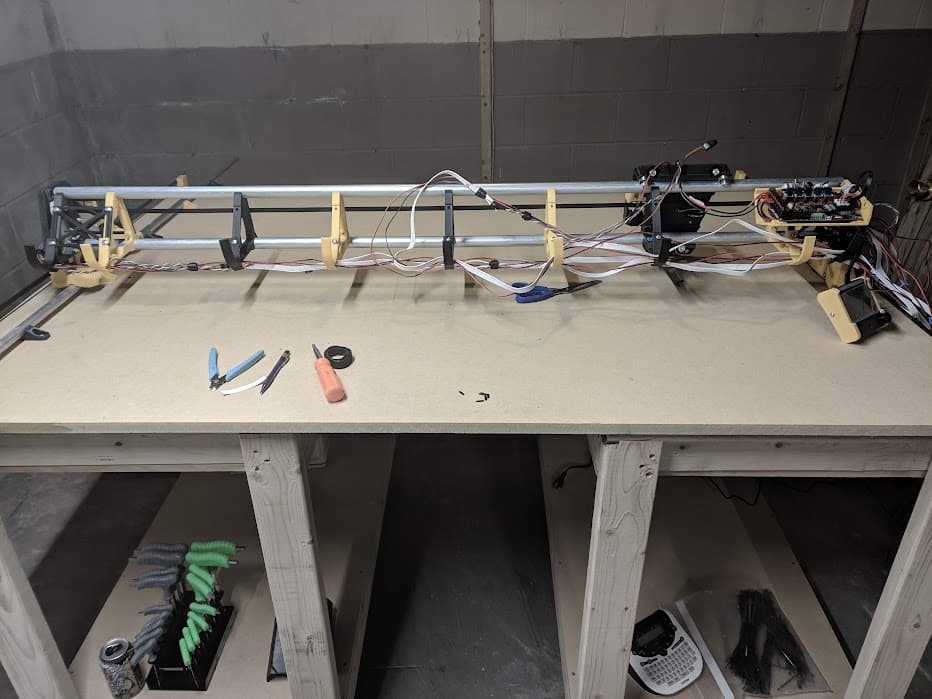
I did some tinkering on the living room floor in Dec and January, but I needed to figure out at least a temporary table solution. With that figured out, I’m back at it.
Only issue I’m seeing right now is that with all the unplugging and moving, I seem to have broken my end-stops that were working the last time I had everything hooked up. Things are looking good, so now I’m terrified that there is a grub screw that I missed with threadlocker! Hopefully will get the end-stops figured out and will be cutting my strut plates soon.
Almost there! You can read the end stop states by typing M119 in the terminal or if it is connected to your pc. They should all read “triggered” except for the touch plate that one is open. Maybe this helps to figure out the end stop problem.
Your table doesn’t look long enough to cut your struts?
Deleted post, because I posted to wrong thread.
But I noticed you have the small power supply- how are you routing the extension cable to the power supply so it does not get caught up?
Is that a 12v or 24v supply?
That’s exactly what I did and resolved the issue… sometime between testing and labelling I swapped my Y and Z endstop wires. I know it was a labelling issue because both sides were swapped the same way. Except for the cramped quarters, it was an easy fix.
@srcnet Correct, I’m hoping to be able to cut on the diagonal, or I will pin and move the stock. Since I don’t currently have a vehicle that can move large amounts of wood, I am going with what was laying around to try to make progress. If it becomes an Issue, I guess I’ll be building my permanent table sooner than I expected.
@Anthony0281 It is the 12V that came in the LR3 kit. Right now it is laying across the table, as you can see, I haven’t finished up the wiring. I’ve debated running it all inside the Gantry, including a plug for the router and the power supply. Then having that come off the side with the Vacuum Hose.