I don’t think so. I can’t be certain, though. If you built the Primo as short as possible and raised up your bed to the minimum, I think something like 1/4" AL should be within reason. You can move fast and shallow or deep and use lots of air and maybe a mist to get the best results.
1 Like
Thanks Ryan. Idk why I mixed up burly and primo, currently have a burly and was about to start on the upgrade to a primo and came across your LR3 release notes. Really like the design! May still go the LR3 route, trying to figure out my workspace a bit. Being able to store the gantry on the shelf and still use the work table is appealing.
1 Like
I´ll probably be using a 32mm hose for my LR3. Are there any remakes of the dust shoe for smaller diameters, or can I just print a simple adapter fo fit the original?
Adapter, would be easy.
1 Like
I ended up settling on shallower passes, bigger stepovers, and much higher feeds. Very reliable, and the carbide never seemed to care about wear in the aluminum, similar MRR to deep passes, much more reliable (on my machine).
I do like having the second x stepper on the mpcnc, but I’m not sure how much performance it lends over tje lr3 single stepper.
What lengths should endstop wiring be (4’x8’ build) for folks needing to crimp/solder wiring with SKR boards? For the dupont-to-spade connected SKR-to-endstop wiring.
Didn’t see wiring length list in LowRider CNC V3 - V1 Engineering Documentation, or, on LowRider V3 Calculator - V1 Engineering Documentation if wiring length varies with build dimensions.
Currently skipping wiring of micro switch endstops for Core and Y/Z drives, until I have enough assembly done to measure actual length needed.
Initially, late night ordered kit with SKR, had enough sense to explicitly add Endstops and wiring items. But now, being several weeks later… Was stumped for a bit during Core’s microswitch step until I realized/remembered only Rambo comes with endstop wiring with spade connecters.
1 Like
this does not work well if the steppers have connectors instead of just wires coming out… the connector is hidden behind the YZ MDF plate and isnt enough room for the connector even if you pre-install.
I pointed mine out as theres enough clearance that way if anyone cares.
1 Like
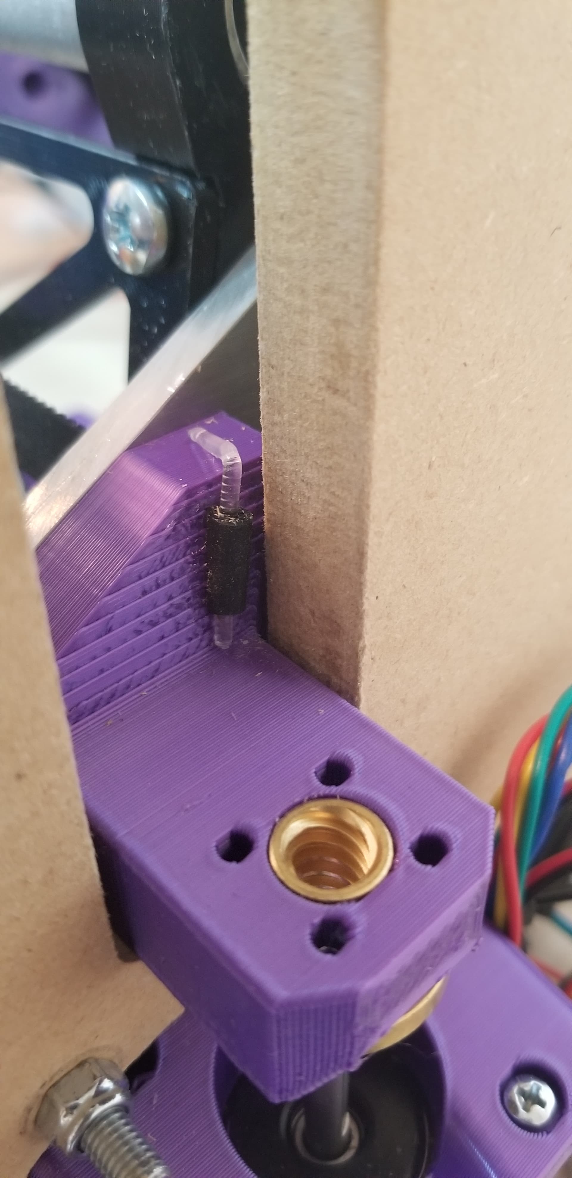
Can you include a picture? I am having trouble visualizing where the interference is.

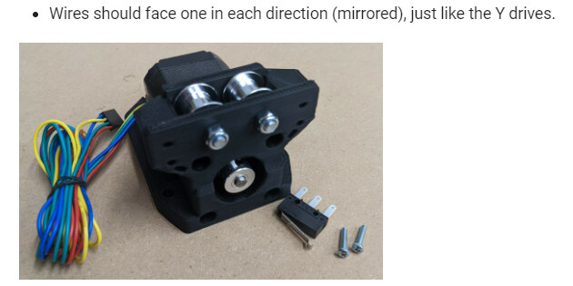
He means here. This is a wired stepper, so the wire outlet is small, but the ones with a plug have a 6 pin JST connector there which is difficult to get to. For the motors that V1 sells, and others of this style, it is obviously a non-issue, and it is desirable to have the wire come out the side like this.
2 Likes
I must have the same motors as you and have also rotated 90 degrees to get access to cable connection
1 Like
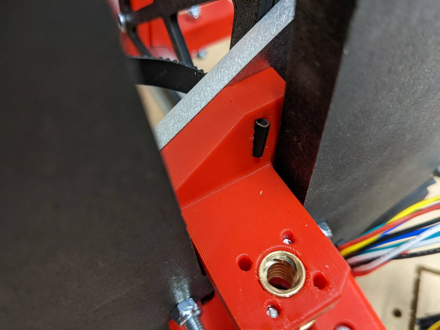
My X axis belt keeps failing, it slips through the xz-leadscrew-stub-right slot. My slot hole is too wide/loose. Anyone encountered this?
Cause could be me over tensioning (guessing 10lbs, not sure what note that should sound like?), and/or my printer calibration, or something else? Either way, everything else has been a nice tight fit. I have been lightly reaming holes before screwing, I reverse drill when reaming to avoid boring too much material, but make screwing easier.
Planning to insert paperclip/pin/bolt to prevent belt pulling thru. This may require me gouging top of the YZ plate so Z movement isn’t interfered with.
Personally, I really like the loop back design on the left xz tensioner stub. Maybe similar approach on the right stub would be more resilient, or, maybe inserting M3 thru the top of stub for belt to wrap around back out the side? I know very little about this project, would appreciate recommendations. Cheers!
Related doc image:
10 is too tight, shooting for 5-7.
At this point it is probably stretched out a bit. I would add a shim or just stick a small piece of filament in the middle of it.
There really was not enough room on the plates for the loop back, maybe I cna come up with something else for the stubs if this pops up more.
Oh, you printed them laying down, if you print them sticking up it might give you a different result. You did it the stronger way but it does mess with that slot. Surprised that was not a complete mess of overhangs there.
1 Like
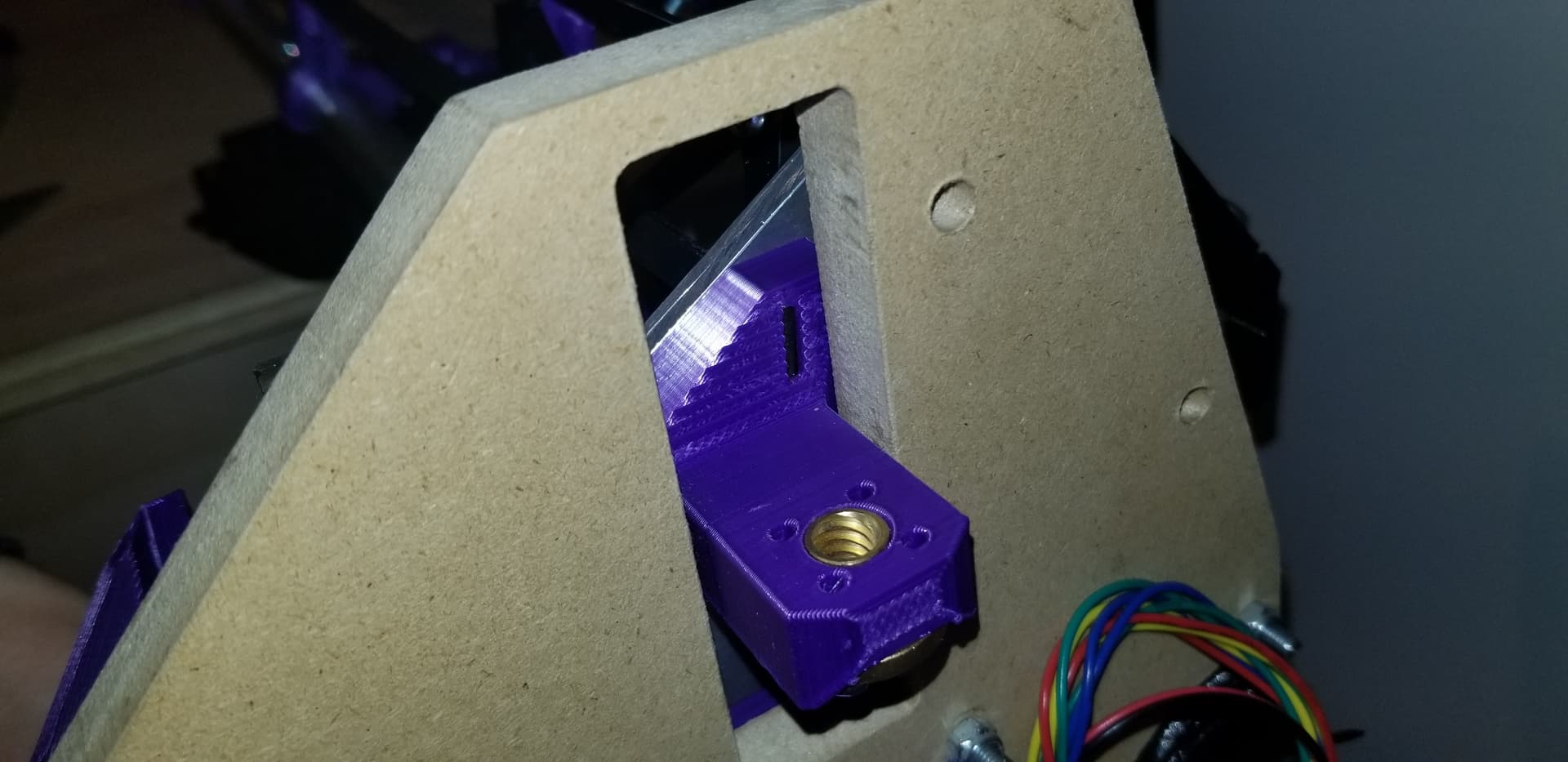
The red LR3 pic is from the docs. Here’s my Purple LR3, printed with 0.6mm nozzle, 0.32mm layer height.
Cheers for the suggestion. Will workaround/quickfix.
1 Like
Sweet. I thought that was crazy how similar it was.
For those pictures I had no more matching red and I had to actually carve out the overhangs when I printed them wrong, that is how I knew it wouldn’t work well, 
3 Likes
I actually had the opposite: my slot was too narrow, and I could barely squeeze the single belt through it, no way a doubled-up belt would come back through on mine. I may have had some over-extrusion happening.
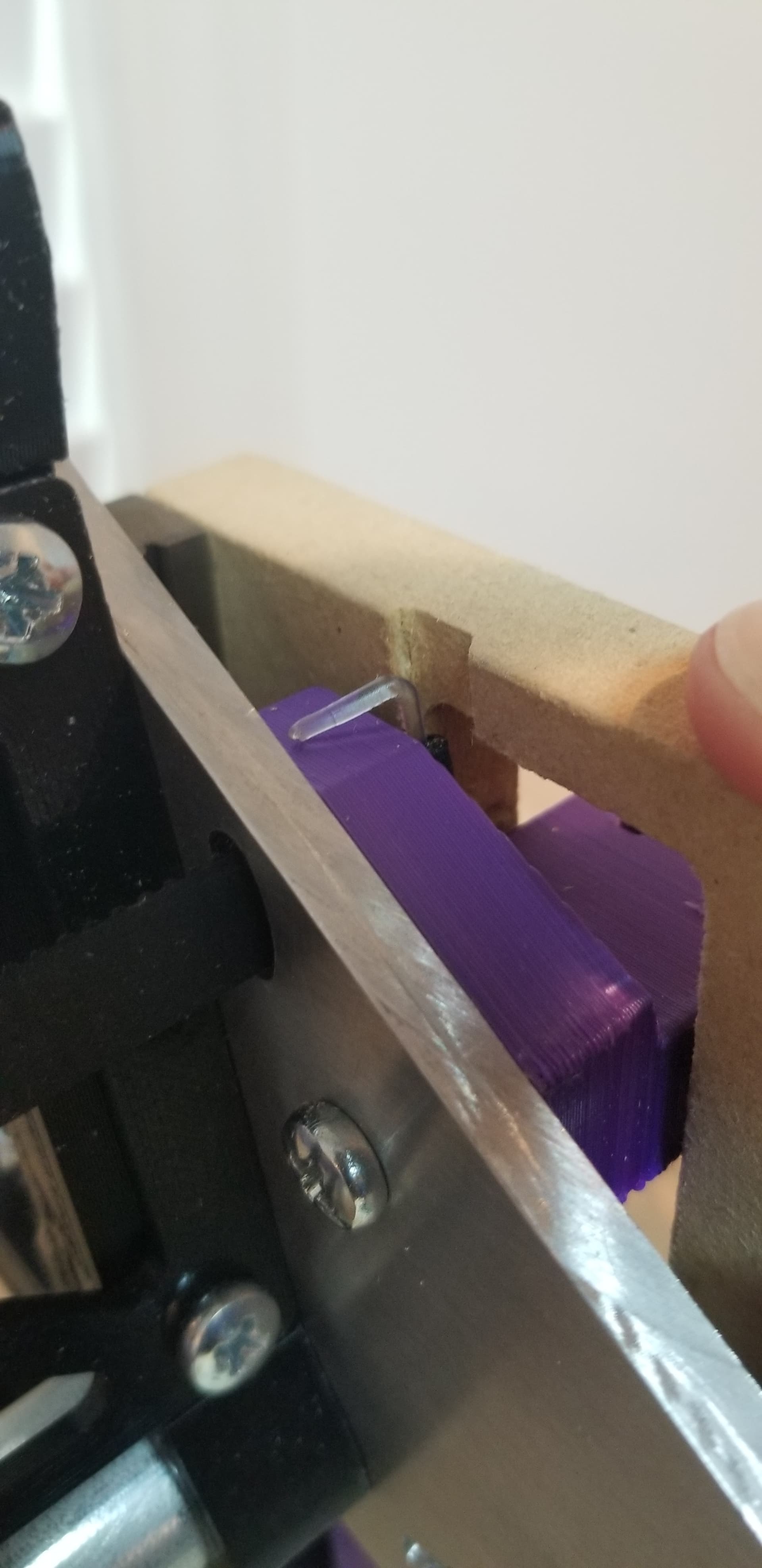
Inserted and bent some PETG, slightly notched YZ. If needed, will glue or something that doesn’t compromise the belt.
1 Like
It has a notch in it, it should not come all the way through doubled up. Sounds like yours printed right, you can ditch the filament I bet.
1 Like
Mine never needed any filament or other pin of any kind.
1 Like
Have you made a 3’ one yet? Mine is 3 feet. I tried adjusting the 4’ provided in the v1 LR3 page but it comes out wonky and all the stuff Ryan did I cannot decipher as I am still a fairly new beginner to Fusion. Mainly vases and small stuff for 3D Printing. Still learning. Hoping my certification course comes through soon for acceptance so I can get on the same level as you all!
1 Like
Looks like @jamiek included a LR3-strut-plate-variable_900x6.svg that’s pretty close to 3’, see Printables , think the set of struts he uploaded are generated using his OpenScad based script that can be used to make any strut length you’d like.
Also, @tgm022861 made parametric Fusion version at Fusion 360 Parametric Model for Strut
Both options look cool, haven’t tried out either yet, still wiring…
3 Likes