I actually had the opposite: my slot was too narrow, and I could barely squeeze the single belt through it, no way a doubled-up belt would come back through on mine. I may have had some over-extrusion happening.
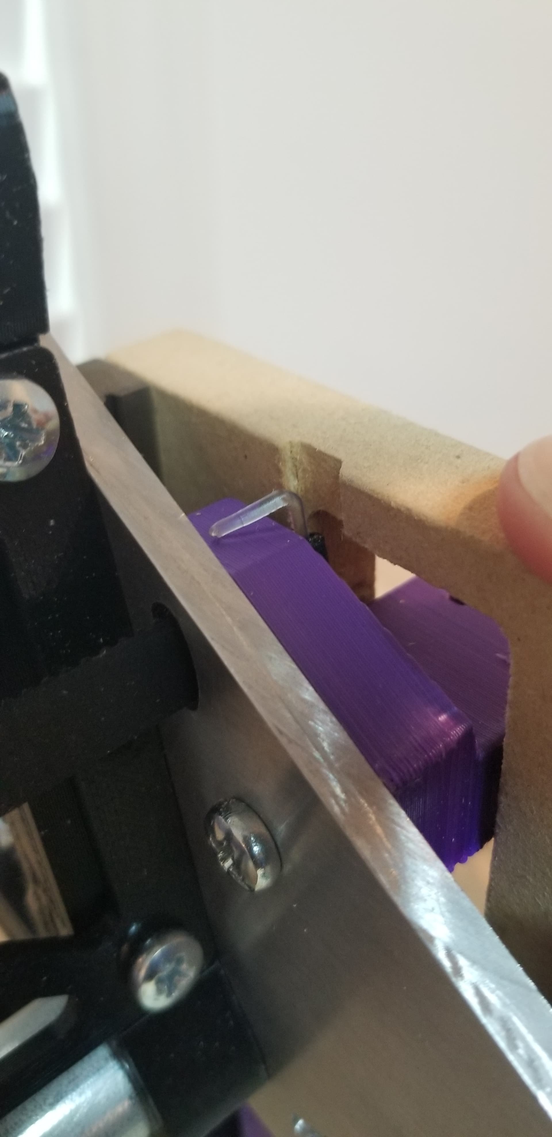
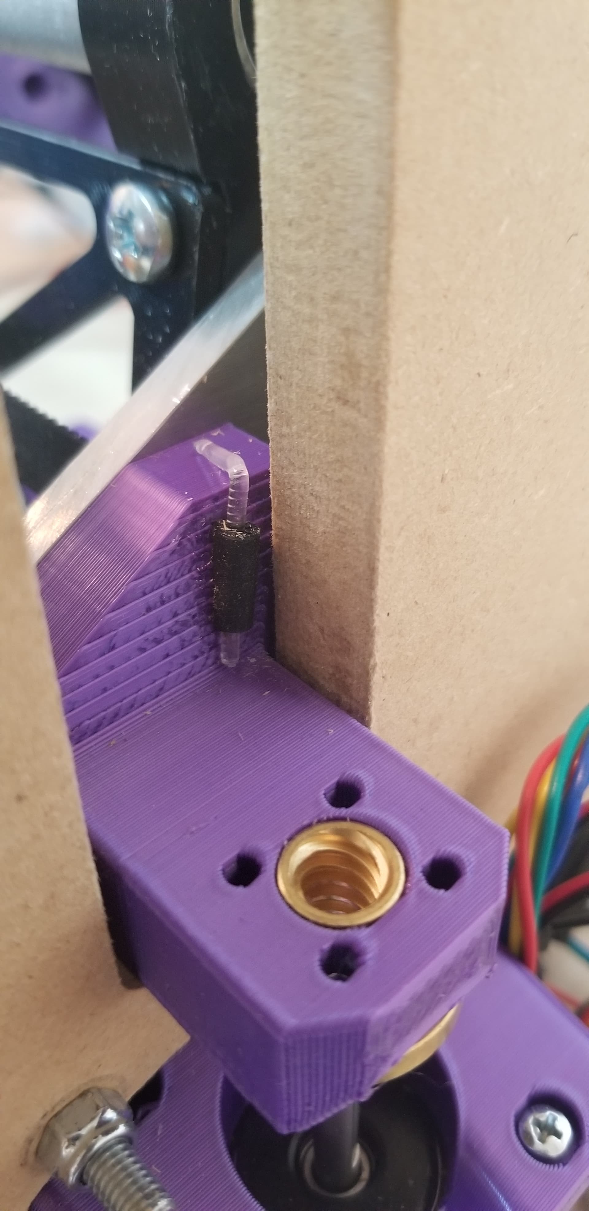
Inserted and bent some PETG, slightly notched YZ. If needed, will glue or something that doesn’t compromise the belt.
1 Like
It has a notch in it, it should not come all the way through doubled up. Sounds like yours printed right, you can ditch the filament I bet.
1 Like
Mine never needed any filament or other pin of any kind.
1 Like
Have you made a 3’ one yet? Mine is 3 feet. I tried adjusting the 4’ provided in the v1 LR3 page but it comes out wonky and all the stuff Ryan did I cannot decipher as I am still a fairly new beginner to Fusion. Mainly vases and small stuff for 3D Printing. Still learning. Hoping my certification course comes through soon for acceptance so I can get on the same level as you all!
1 Like
Looks like @jamiek included a LR3-strut-plate-variable_900x6.svg that’s pretty close to 3’, see Printables , think the set of struts he uploaded are generated using his OpenScad based script that can be used to make any strut length you’d like.
Also, @tgm022861 made parametric Fusion version at Fusion 360 Parametric Model for Strut
Both options look cool, haven’t tried out either yet, still wiring…
3 Likes
I found the files on printables. I adjust from 900 to 914 and it worked great. It was an svg which i can work with that. Was able to adjust and make. Painting them now. Thanks for the help!
4 Likes
Mine didnt need either. When i took it apart, homy crap its snig in there good! Shouldnt need that!
1 Like
Anyone using tachometer and/or speed controller on their LR3?
Still catching up on related threads/posts. But I see a sensor for sale, but no kit, Optical Sensor - RPM / PID Parts - – V1 Engineering Inc
Would like to run my LR3 at known/expected rpm. Software control would be nice too.
It was more useful for the 660 but the makita and 611 have a built in speed control that works very well. it is really easy to get it dialed in by ear when it holds it’s RPM. The 660 changes RPM with load more.
1 Like
How did the mailing go?
For LR3, digging thru the forum, feels like Makita > 611 > 660. Difference between Makita and 611 not being much.
Was deciding on spindle, part of that involved thinking ahead to probable future mods… Wanted to understand whether the Makita, or the 611 will be easier to modify with tachometer and/or speed control using SuperPID or similar, or some cheaper V1E or custom triac/POT solution even. Operating at known speed, and sending a single job with multiple paths with different speeds would be nice to have in the future. Am coming from Genmitsu 3040 which lets you set and vary speed through out a cut, but no tachometer, so who knows what actual speed is, especially as load varies.
Found @iamthesoundman’s Makita mod to integrate SuperPID Building A CNC Machine | Part 4 | Super PID Wiring & setup with Makita RT0701C | MPCNC Motor Control - YouTube, very helpful, cheers for that!
Sticking with my Makita! Unless someone convinces me otherwise, please let me know soon though, am spraying my Makita to color match my core, as soon as I can track down high temp rainbow spray paint.
2 Likes
If you want speed control, get a spindle with a VFD. That will be better and safer than modifying a router. In the end the price will be similar.
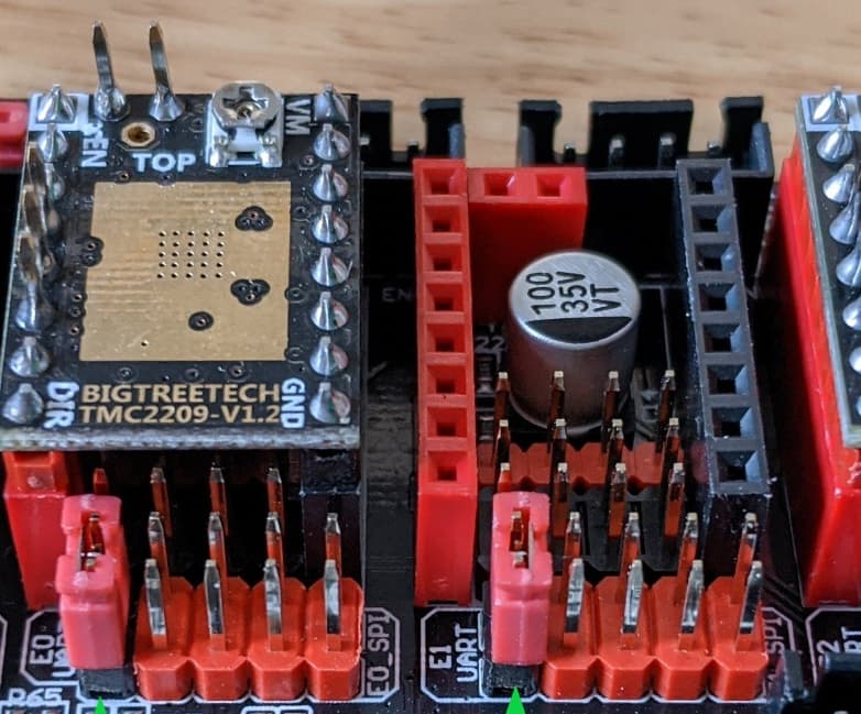
LR3 / SKR docs suggest bending the driver’s Diag pin. Anyone else notice the bent pins could end up touching top of the Capacitor below the driver? No idea if that’d cause an issue (?), and didn’t want to find out, so I’ve been clipping off the Diag pin instead of bending. Clipped pins using cutters I usually use on 3D filament. Pins fly off at high speed, usually straight into your good eye. Don’t rely on safety squints, I recommend eye protection and cover/shield with your free hand during the cut so the shrapnel falls close by.
1 Like
The diag pin is normally at ground (logic low) potential and raises to logic high if the motor skips a step, in either case being grounded is not a problem, so there is no problem if it does touch the cap casing. If bent at least 90 degrees, it won’t anyway.
I bend mine, in case I someday get the desire to implement sendorless homing. No problems on 2 SKR Pro boards so far. (I realize that’s not a huge sample size.)
The SKR Pro board has a problem in that the diag pin connected overrides the endstop pins, so with the diag pin connected you cannot use stop switches, they will be ignored.
3 Likes
Anyone have a link for reusable/releasable zip ties that fit the LR3 model’s ziptie channels?
Love the channels integrated into the LR3 models. But they’re just a little bit too narrow for the 0.2" reusable zip-ties I have. Currently working around by trimming width of the zip ties I expect to be remove if/when making future mods.
Asking after seeing @revnull’s observation about zip tie channel in the braces. Neat design feature. I spent ~16hrs building LR3, but I didn’t notice them, LOL.
2 Likes
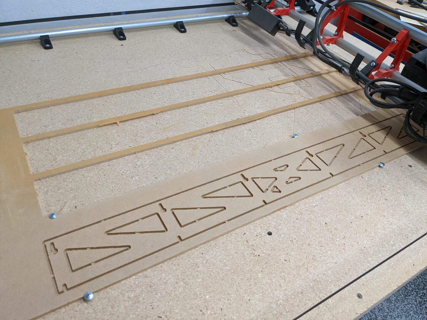
LR3 Docs has pic of Struts with holding Tabs for the cutouts.
Currently doing something like…
- Open downloaded/generated strut .svg/dxf into Estlcam
- Select menu Automatic functions → Create objects automatically
- Select all toolpaths (Ctrl + A)
- Select menu Automatic functions → Create holding tabs
- Within Create holding tabs popup, update with following settings, then ok.
- Nominal distance 100mm
- Min count 2x
- Max count 15x
- Within Create holding tabs popup, update with following settings, then ok.
- While all toolpaths are still selected. Edit Holding tab height from Full to instead be 3mm
- Click on Preview icon (bottom left)
- Enter cutting depth, stock depth + 0.5mm
- Click “>” play, speed up and closely watch the planned toolpath.
- Hold Left mouse button and move mouse to see 3D view, to help understand planned cutting path, and, flight path (dashed red lines) between cuts.
- Menu File → Save CNC program to create .gcode
Please let me know if there’s a better way.
Edit: Measure your wood, it’s probably not as thick as you think. I set cut depth based on labeled thickness, I should’ve known better by now. Ended up catching loose strut cut-outs with the shop vac.
I have never tried any of the automatic functions. I select them all one at a time and then do the machine order after I finish all the selecting and manually placing tabs.
2 Likes
@jamiek thank you for creating and sharing a set of strut plates together with a script that folks can customize.
I foolishly spent some time making a video that may help anyone hesitant to try out OpenScad.
")
Then, sigh… I spent much less time making the video pointless for people that can live with Struts rounded to the nearest 10mm…
I just uploaded Strut Plates .SVG files sized from 480mm - 1700mm, in 10mm increments, to github. Please let me know if they’re wrong.
Edit number in the URL to the nearest 10mm size you need. So, now folks only need to generate a Custom sized Strut if they need millimeter precision.
Ideally, the LR3 Calculator would provide a link to one of these pre-generated static .SVG files. There’s few enough files, that are relatively small (123 files, total of 2.5mb), that the static files could be webhosted. I don’t think on-demand .SVG generation via Cloud App makes $ense. @jamiek, thoughts?
3 Likes
OMG! I love it!
I’m going to link the video on the printables page for the strut if you don’t mind.
As for the pre-generated files, it’s got me wondering… it feels a bit weird, but what about 1300 files? As you pointed out, they are small, and github won’t complain (right?). Then the arbitrary strut length is solved period, no asterisks or caveats about adjusting the size a few mm to be multiple of 10. And the OpenScad model becomes even less necessary.
3 Likes