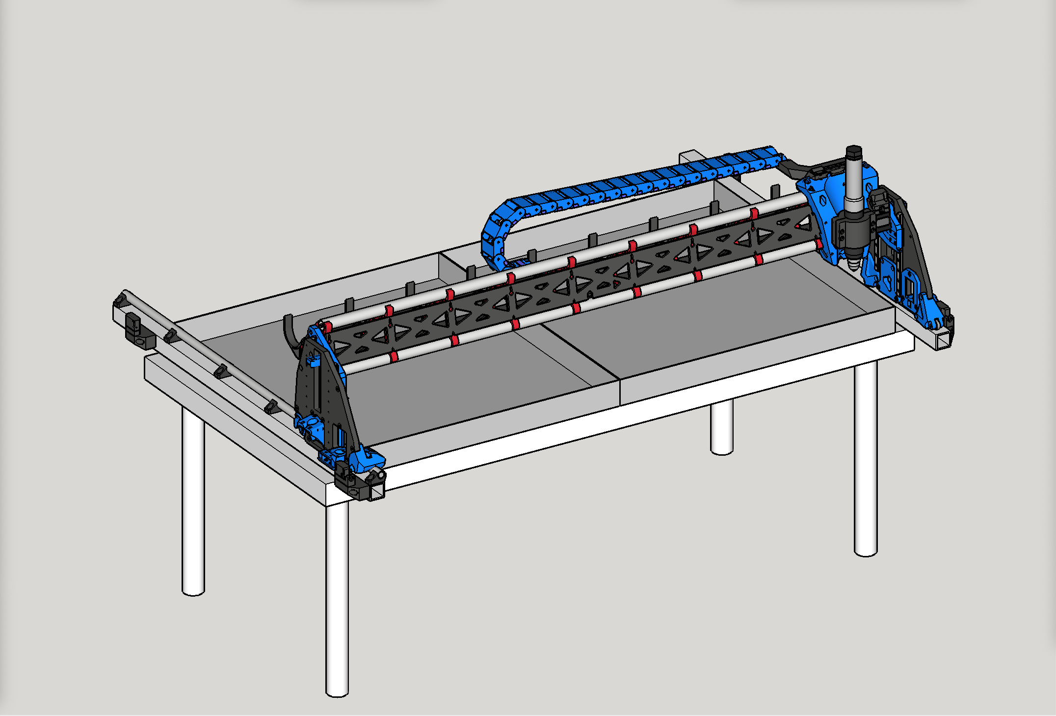
I’ve been refining the 3D model for the overall build, which includes making remixes for 3D printing and some designs for new parts for 3D printing. Along the way, I’ve been printing more and more of the parts needed, while waiting for ordered items to arrive.
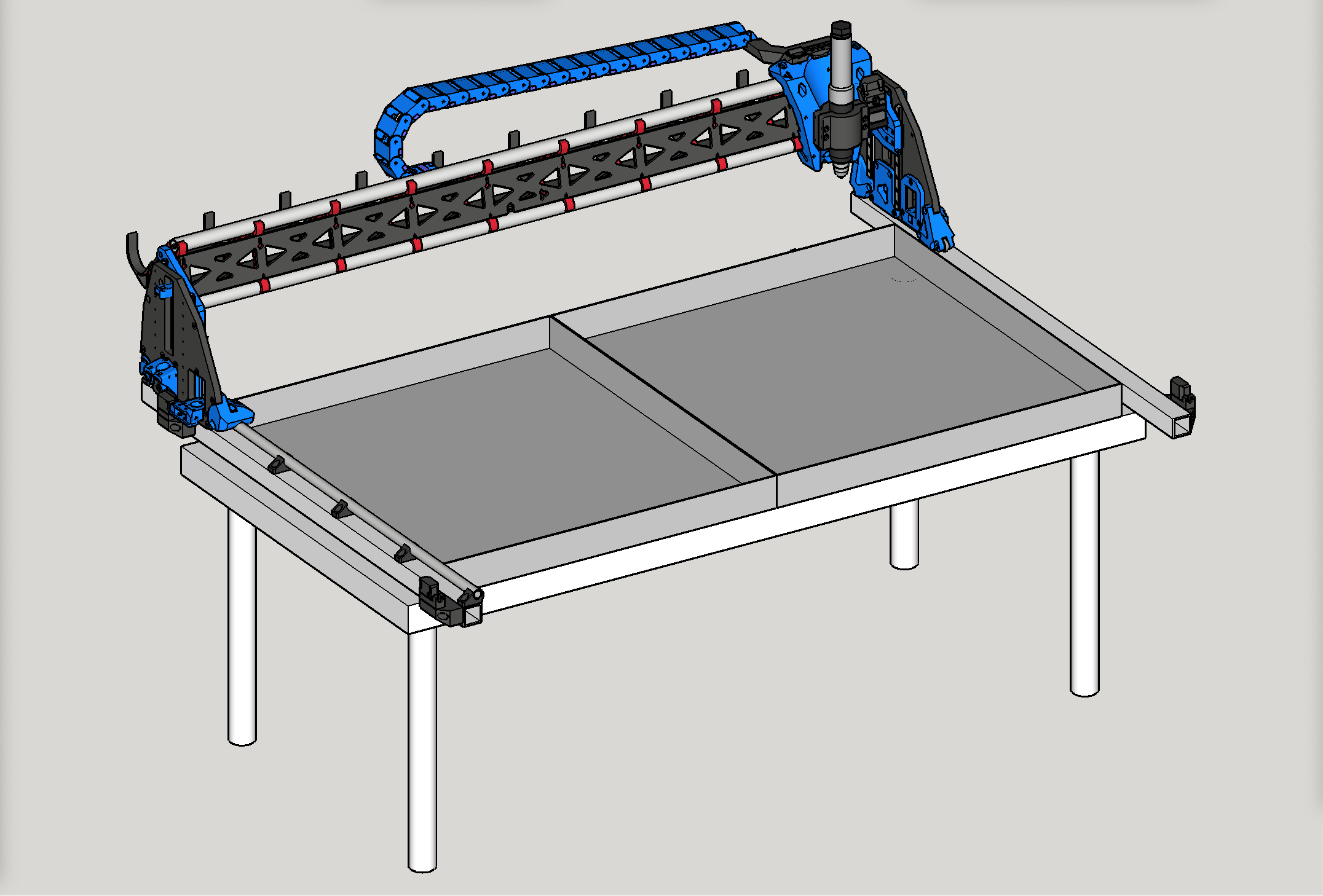
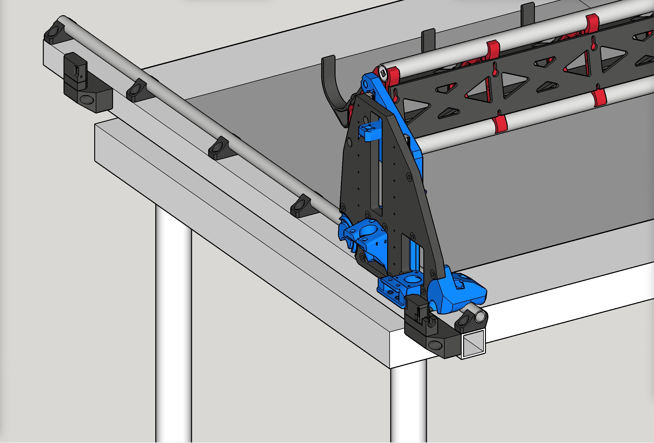
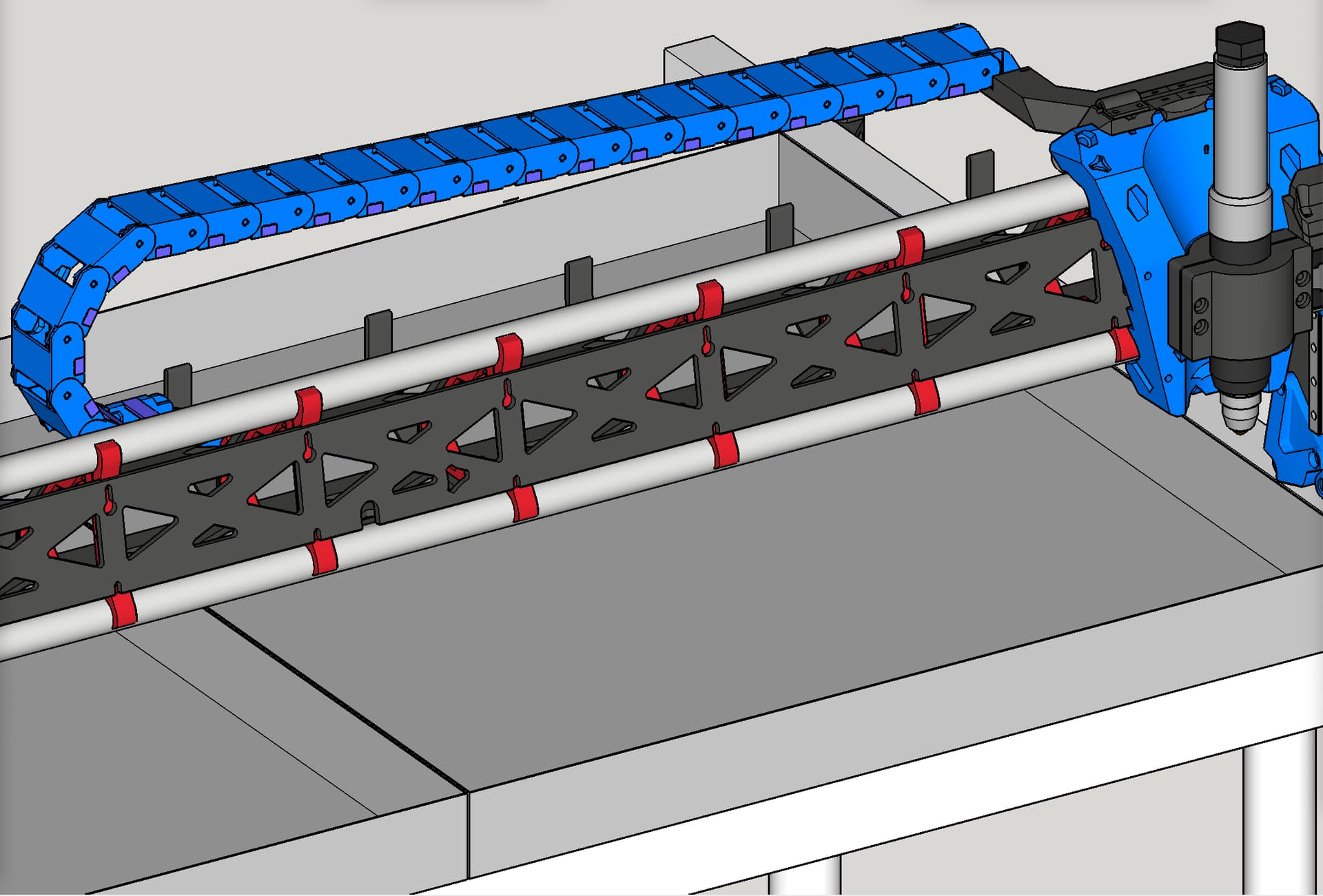
More screen shots are below, which update on the design refinement process.
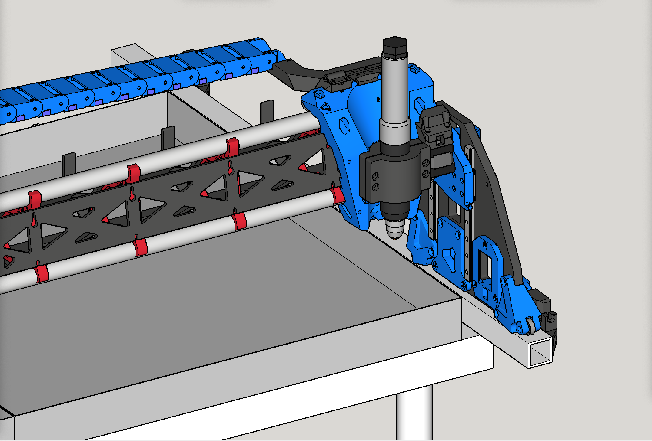
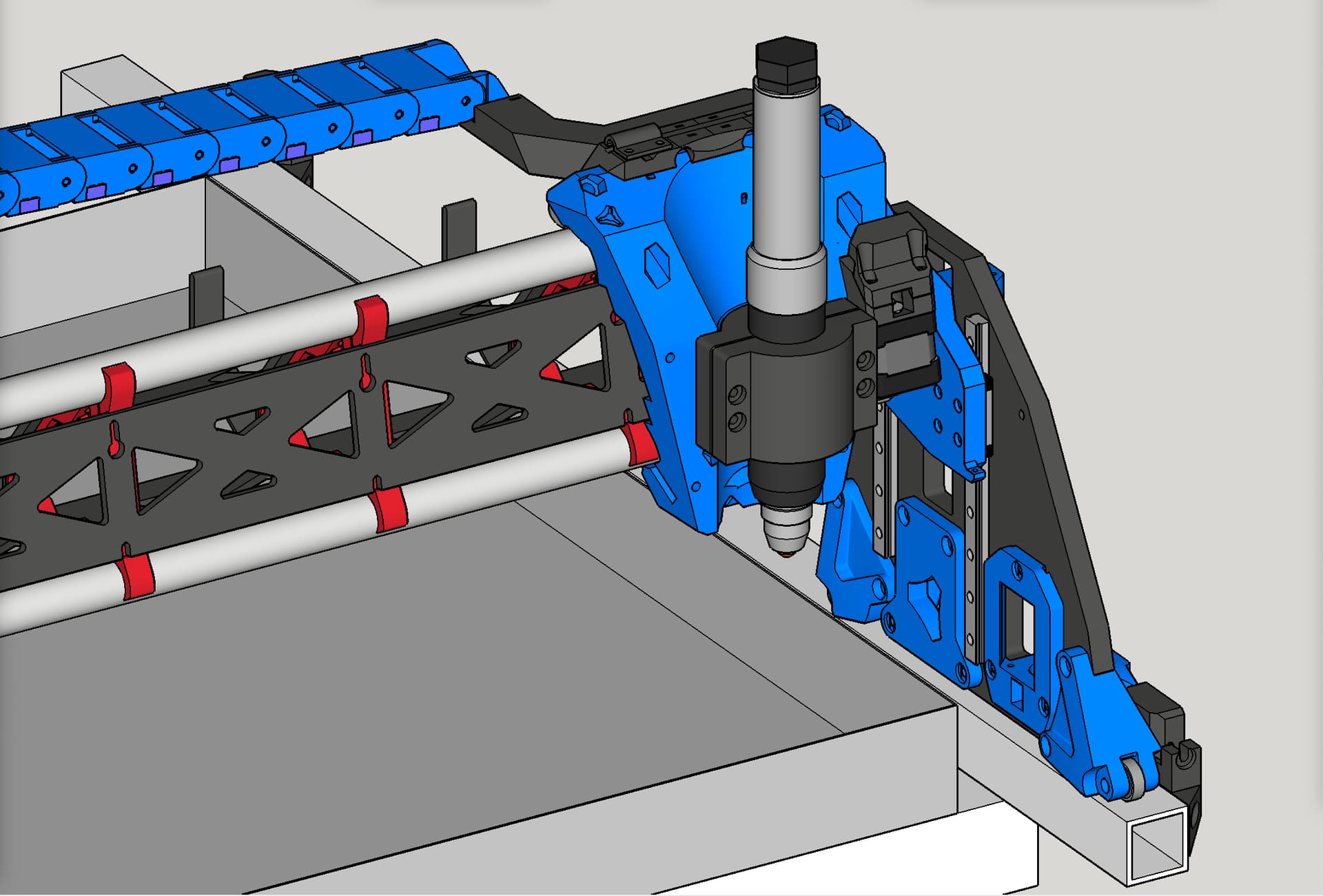
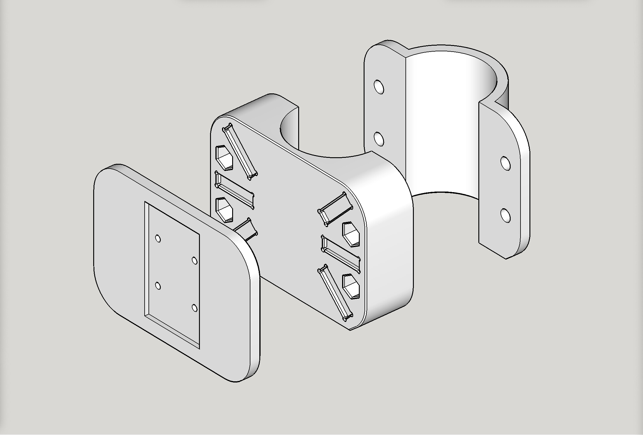
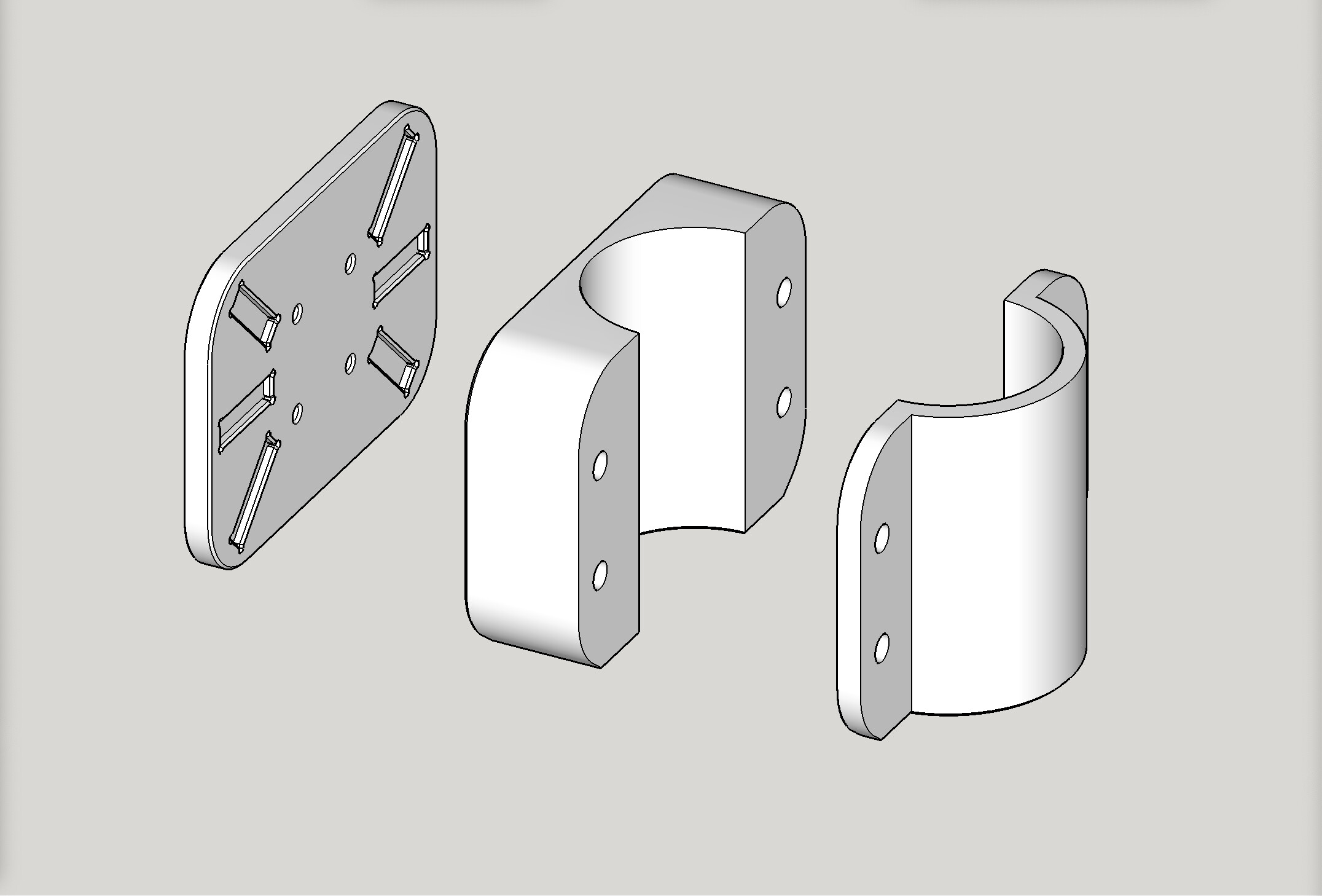
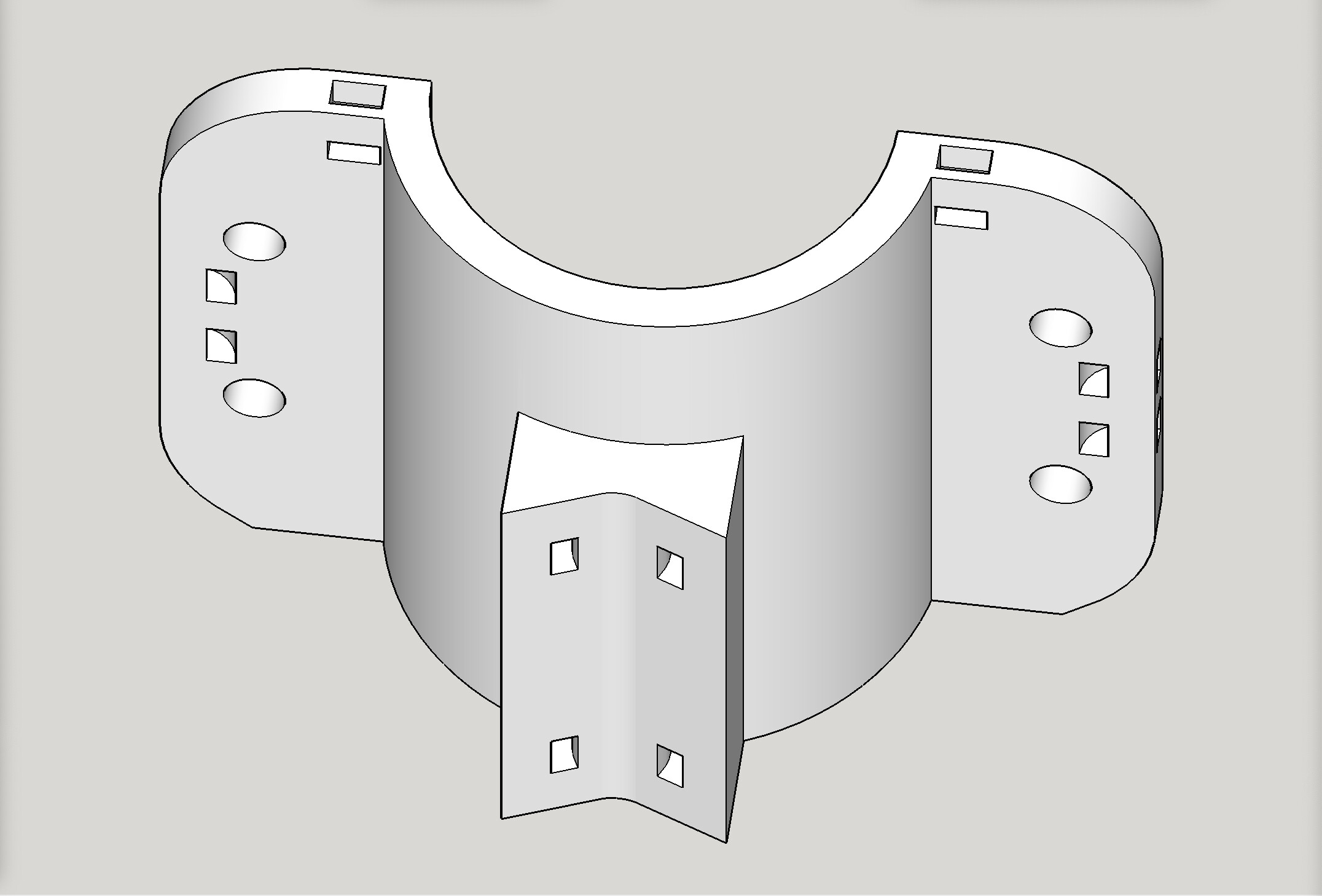
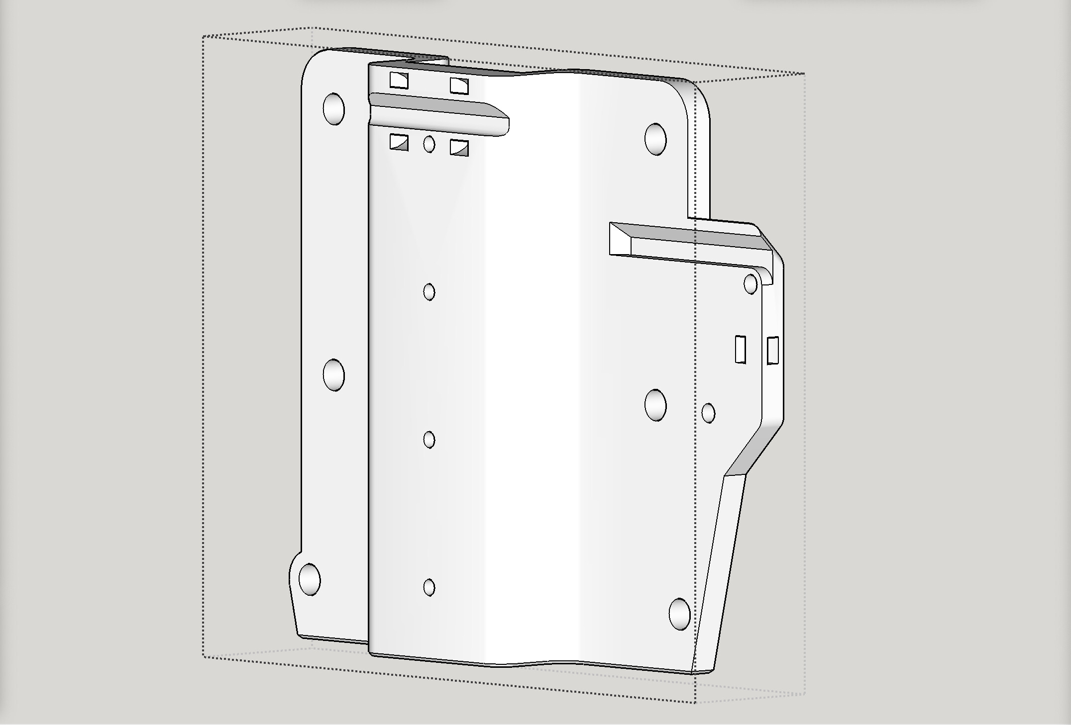
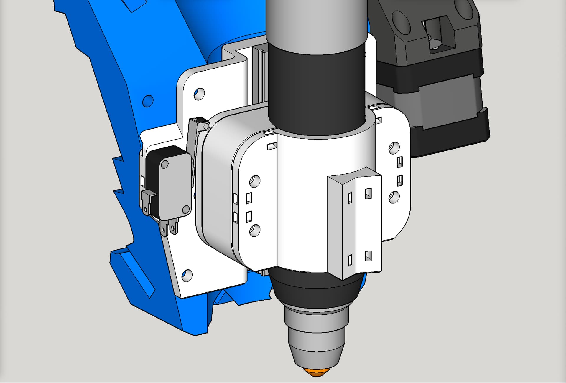
One of the new parts I’m working on designing is the torch mount. I see basically three or four choices for it.
Two-part mount in which bolts secure both parts at once.
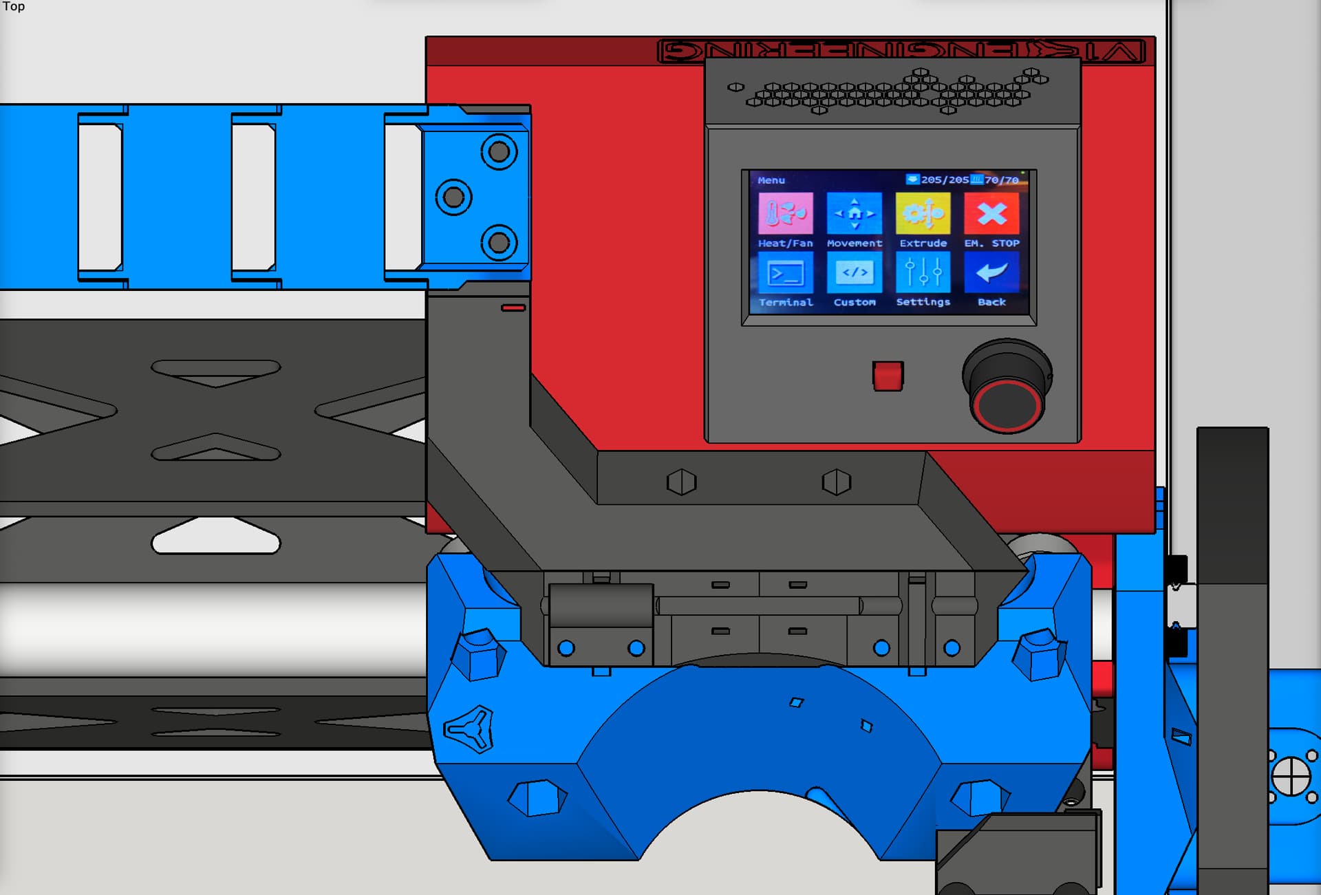
Two-part mount in which bolts secure the first part semi-permanently, and bolts secure second part to first part in a somewhat removable way. This is the current design shown below.
Three-part mount in which bolts secure the first part semi-permanently, and some type of quick release secures second & third parts (and tool) to first part in a more removable way.
Three-part mount in which bolts secure the first part semi-permanently, and magnets secure second & third parts (and tool) to first part in the most removable way, also allowing a “break away” feature if the torch should hit an obstacle hard enough. I’m interested in this approach, but I would probably need to order more magnets to do it.
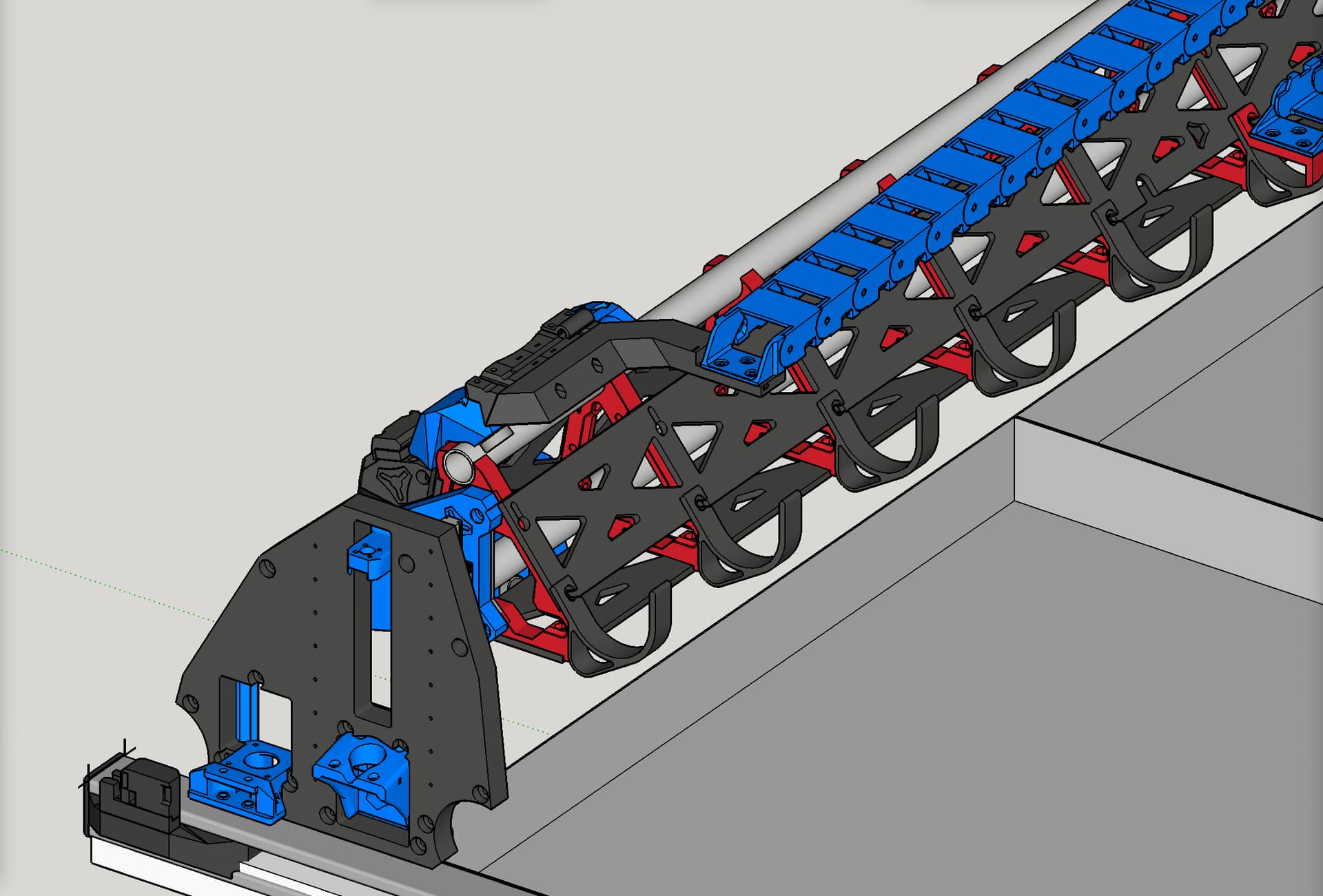
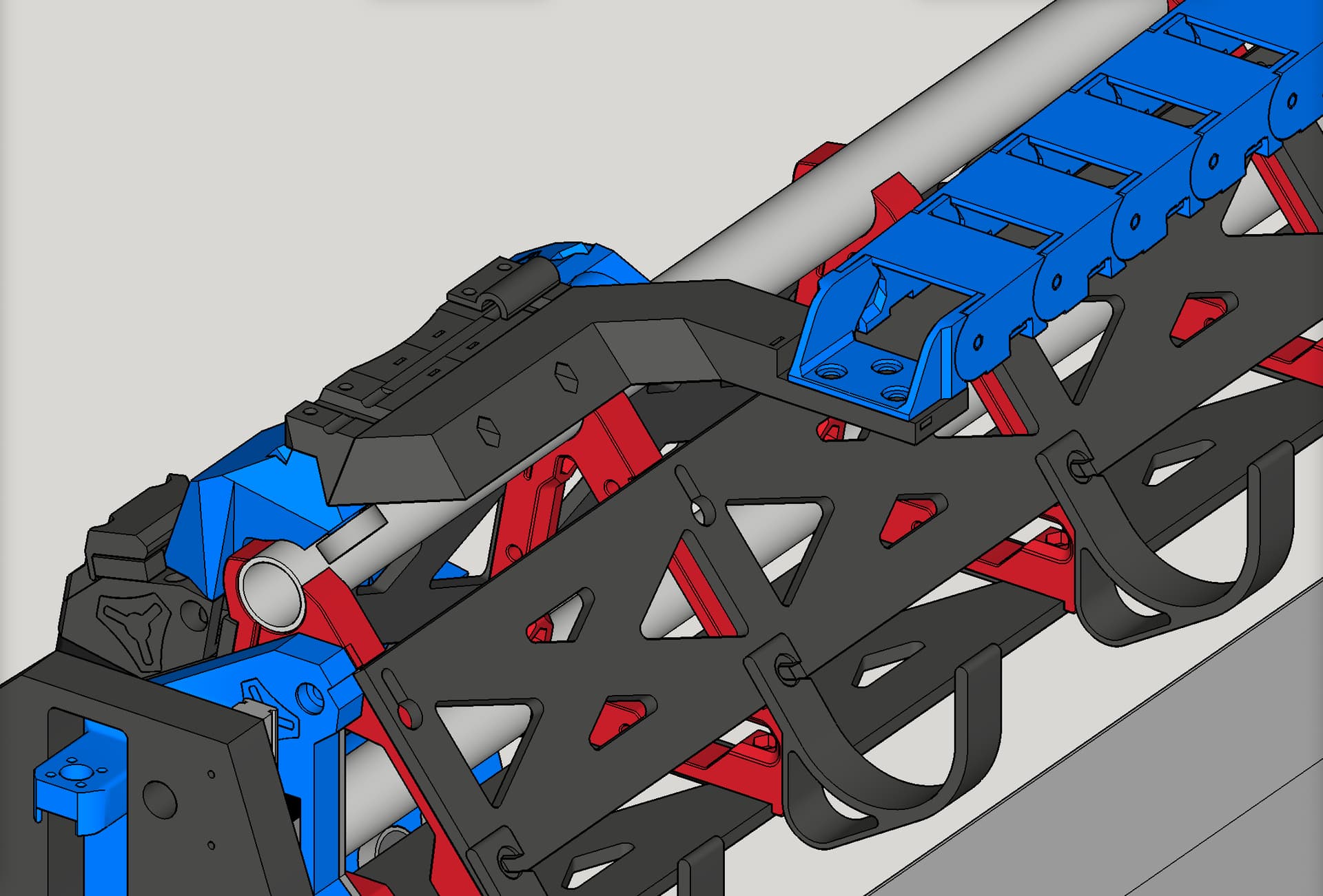
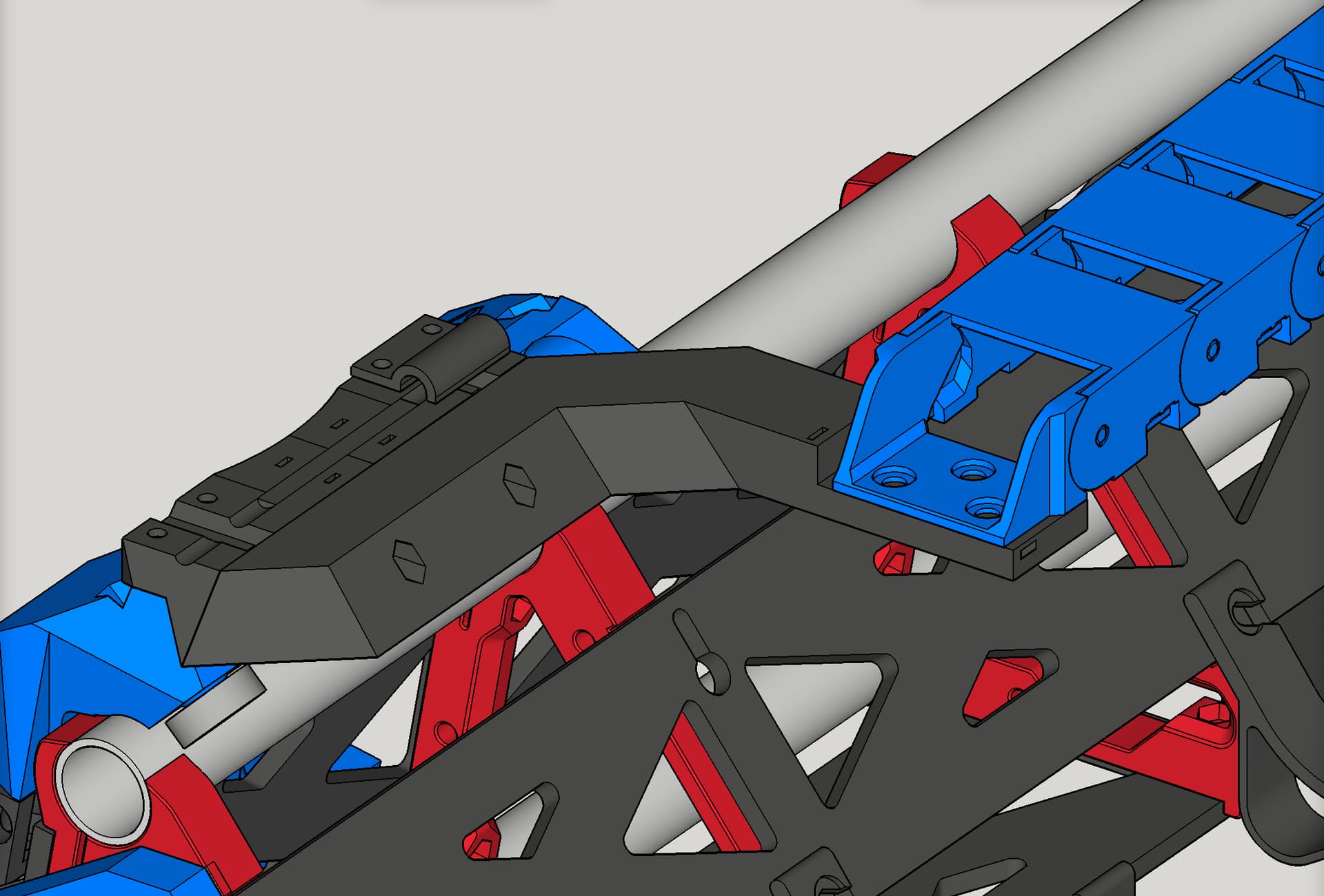
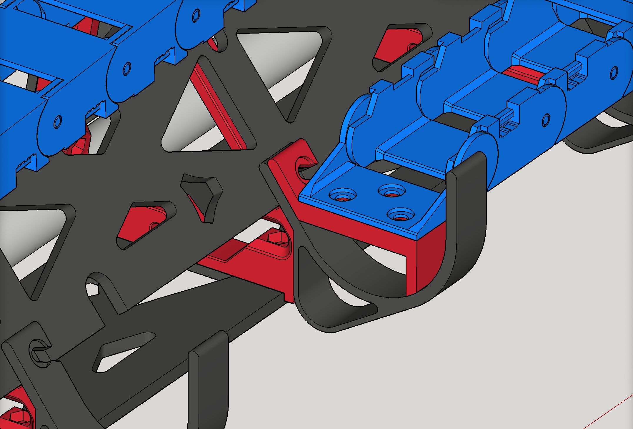
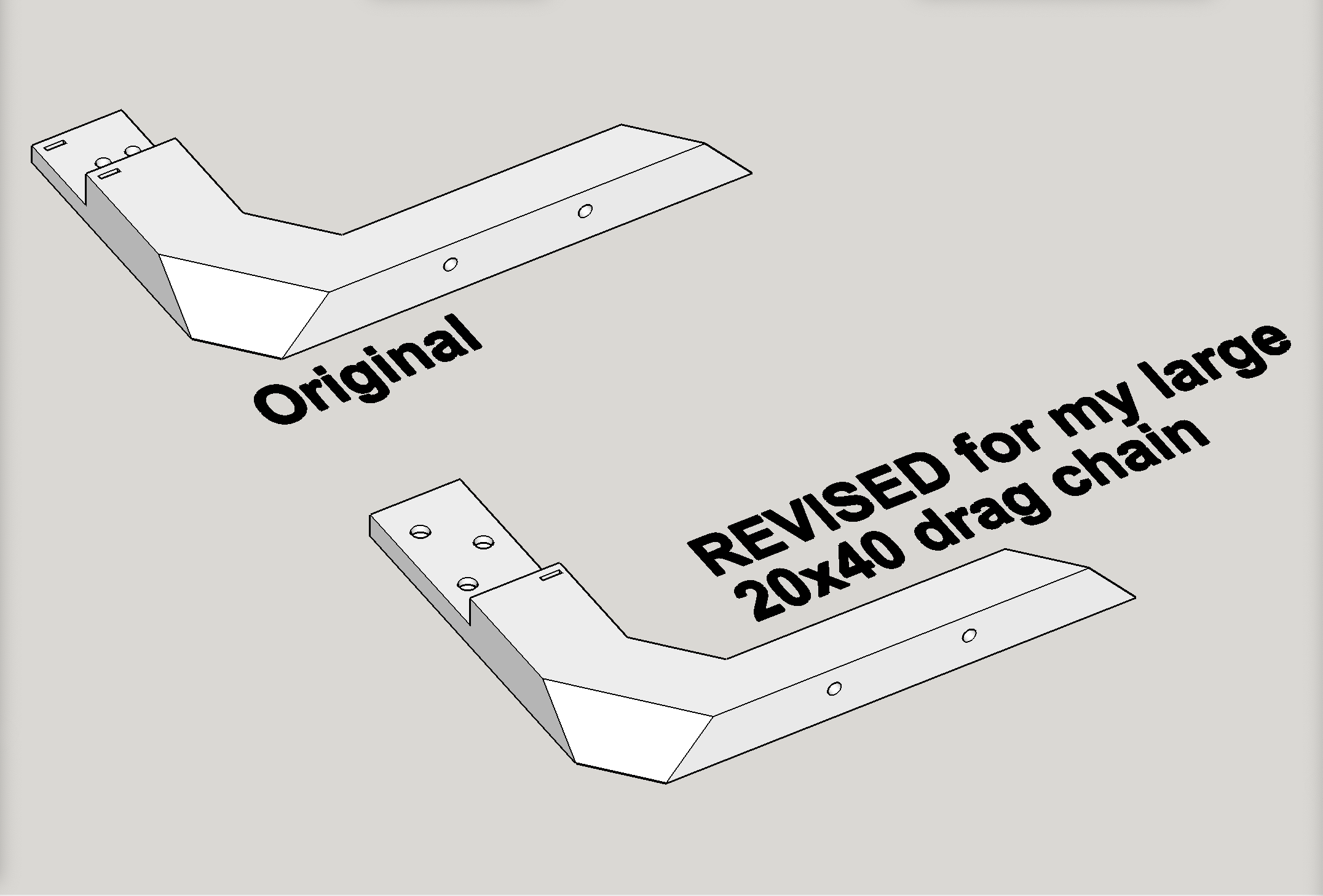
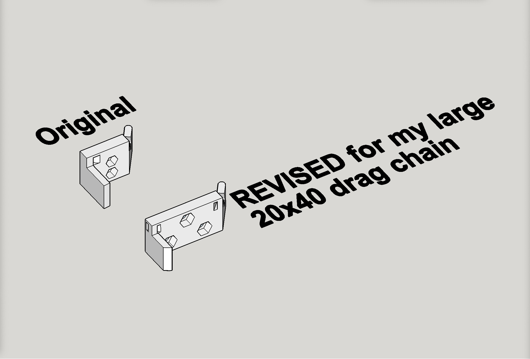
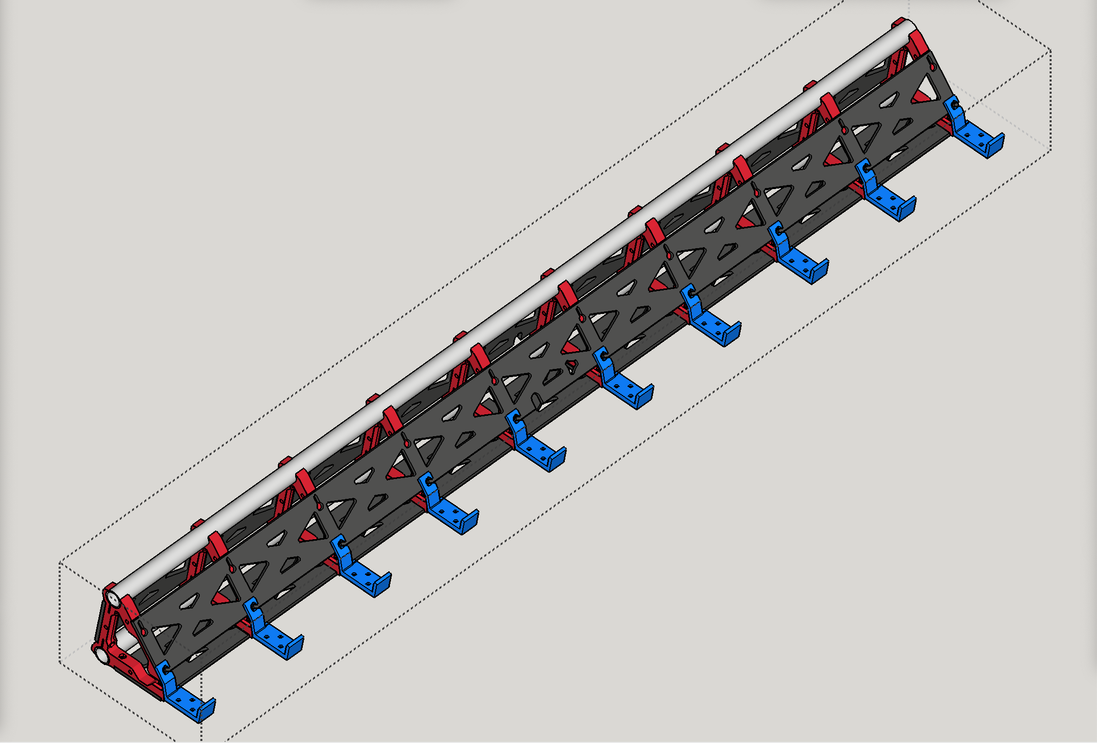
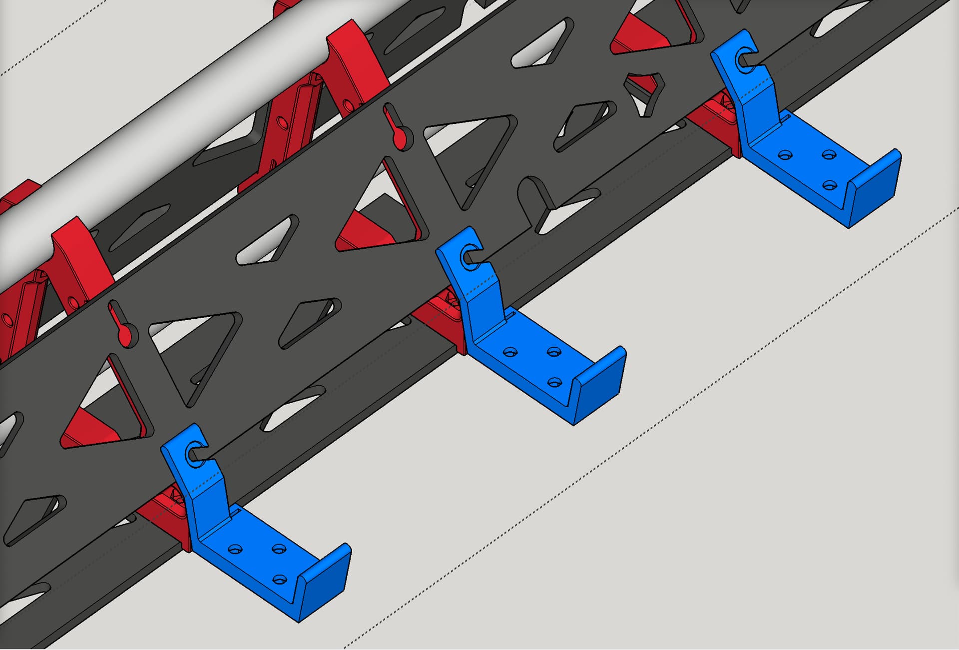
Since the plasma table won’t have a vac hose, but still needs something to hold wires, I’ve designed this remix of the hose hangers. Shown in blue in first two screenshots, gray in the last one. They’re peppered with screw holes and a couple of sip ties channels in each one.
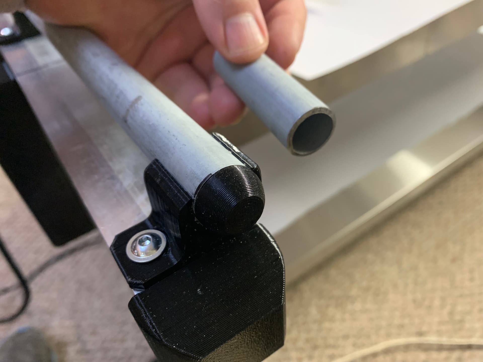
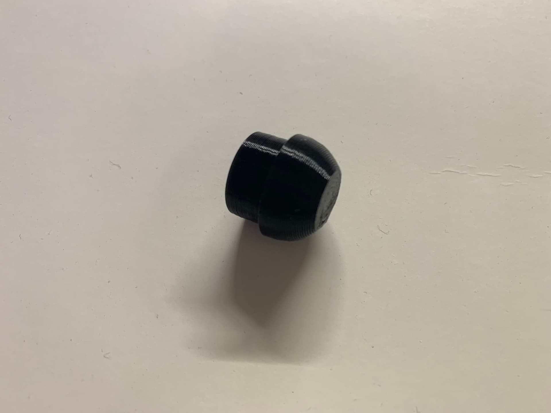
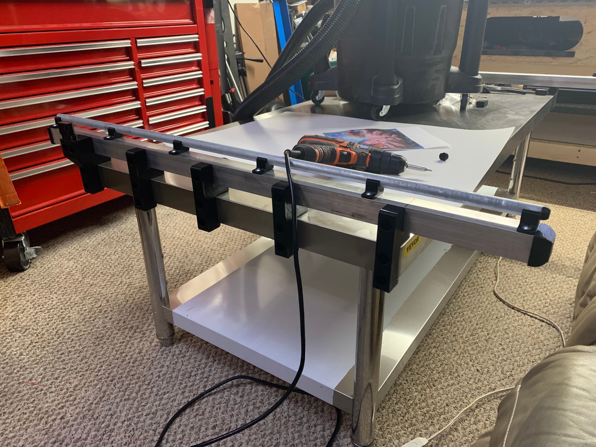
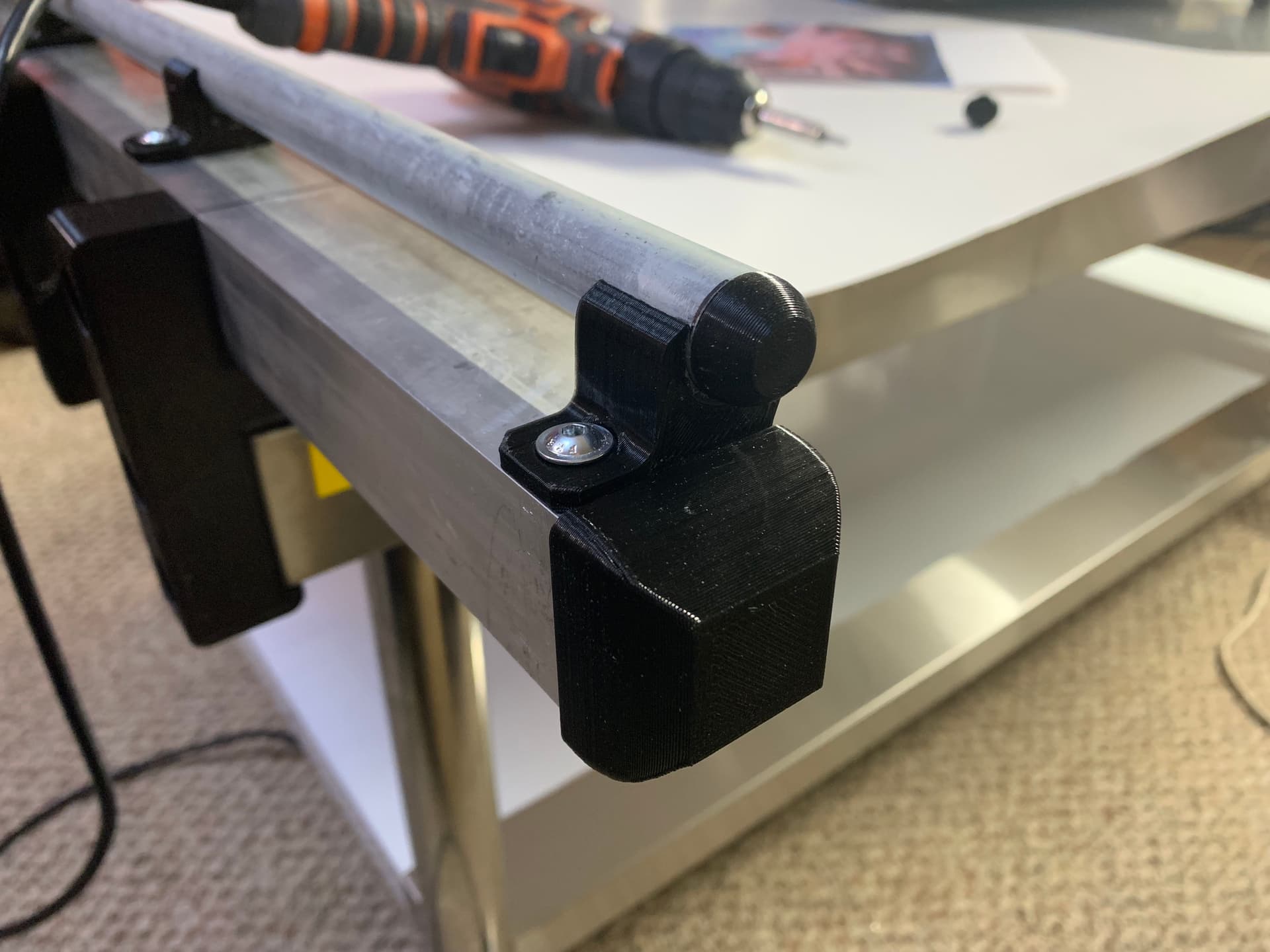
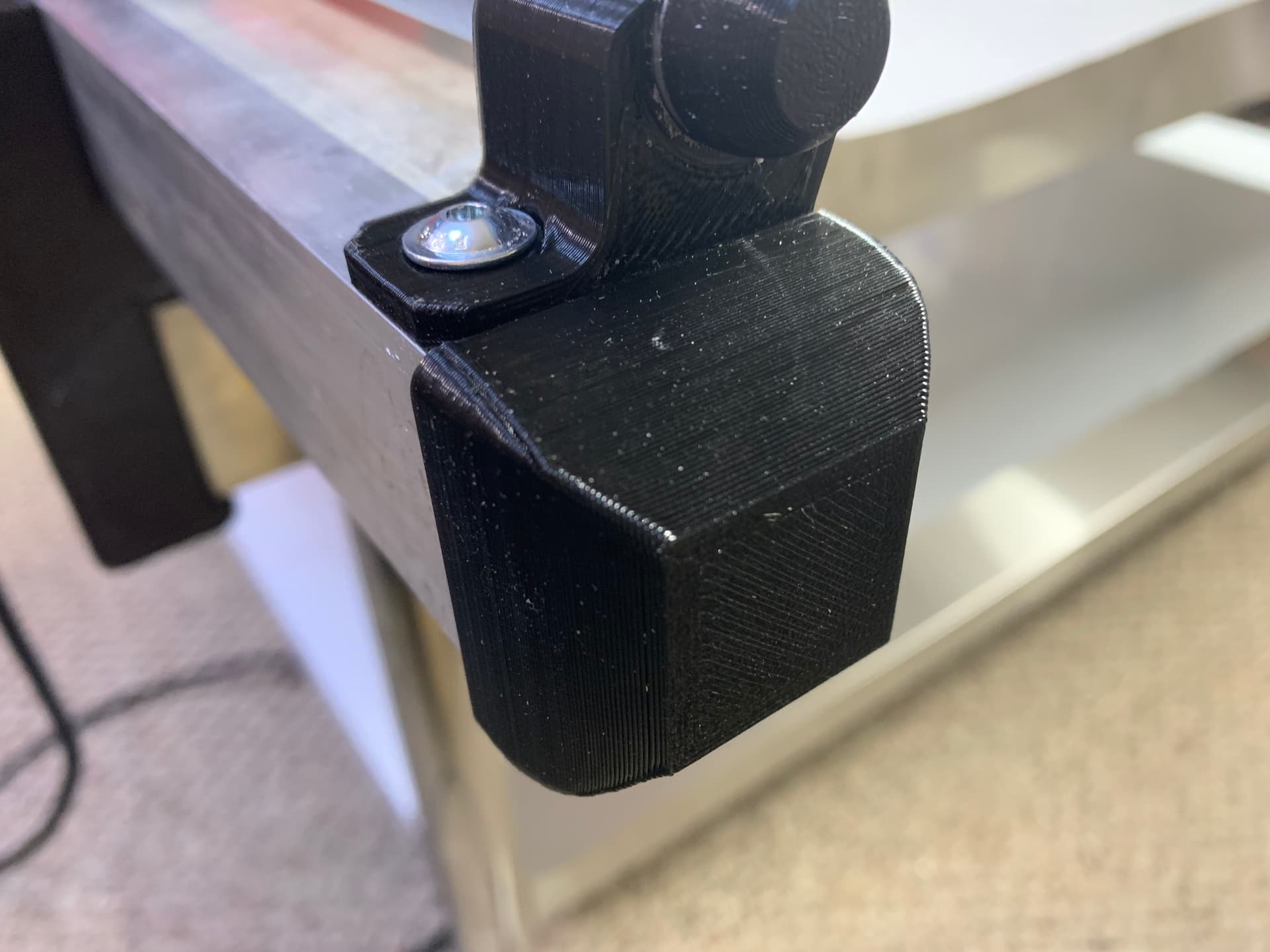
For when using 1/2" EMT (electrical conduit from home improvement stores) in projects such as the LowRider v3 CNC, this end cap protects against snags and scrapes (v1.0). Prints with no supports. PLA. Can be scaled a bit as needed in your slicer to get a tight fit. Mine fits tight just as it is. Also, a bit of painters tape around the stub can help tighten a loose fit. Quick print. For me about 9 minutes each. Enjoy!
For when using 1.5" Square Tube (1/8" wall) in projects such as the LowRider v3 CNC, this end cap protects against snags and scrapes (v1.0). Prints with no supports. PLA. Can be scaled a bit as needed in your slicer to get a tight fit. Mine fits tight just as it is. Also, a bit of painters tape around the stub can help tighten a loose fit. Enjoy!
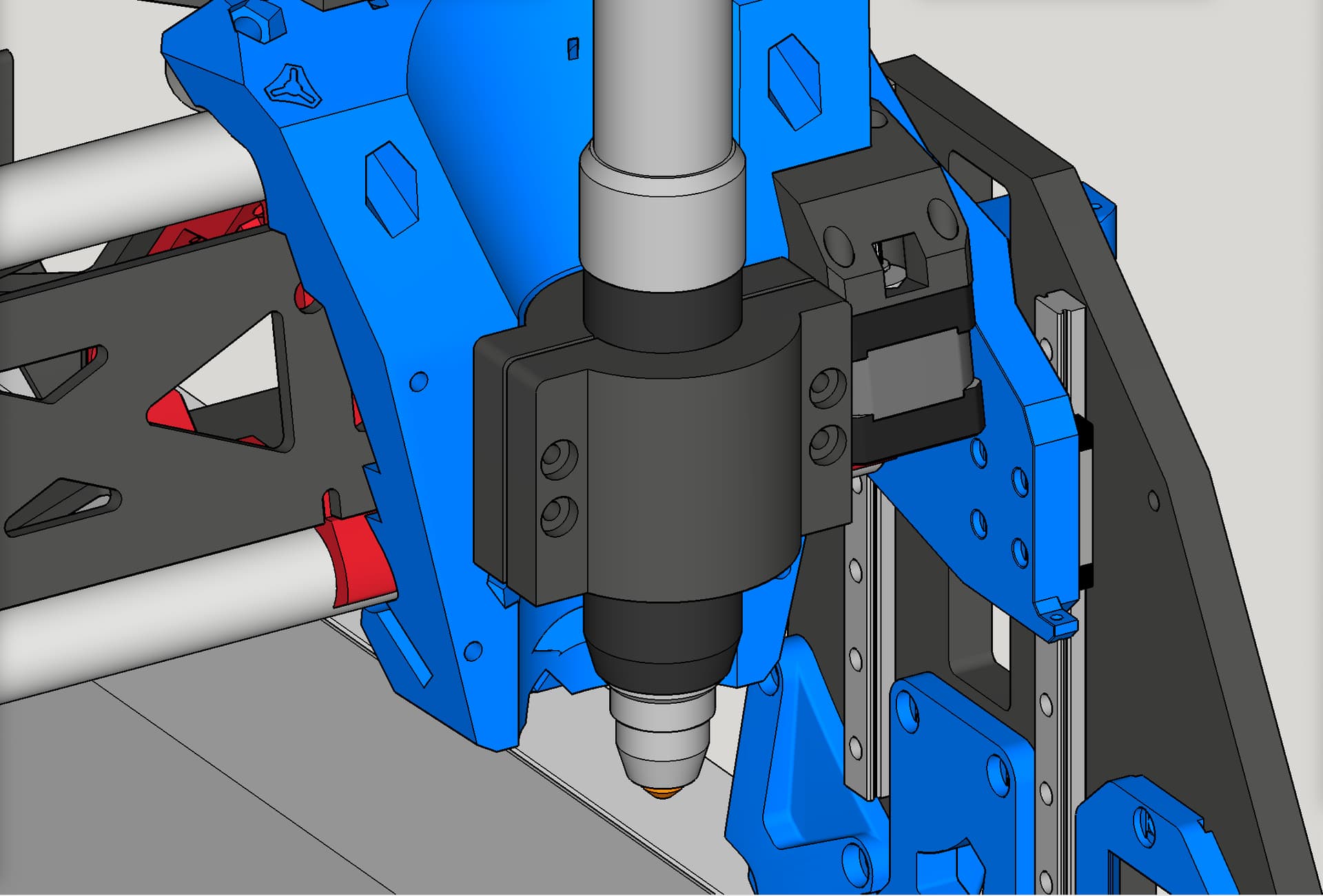
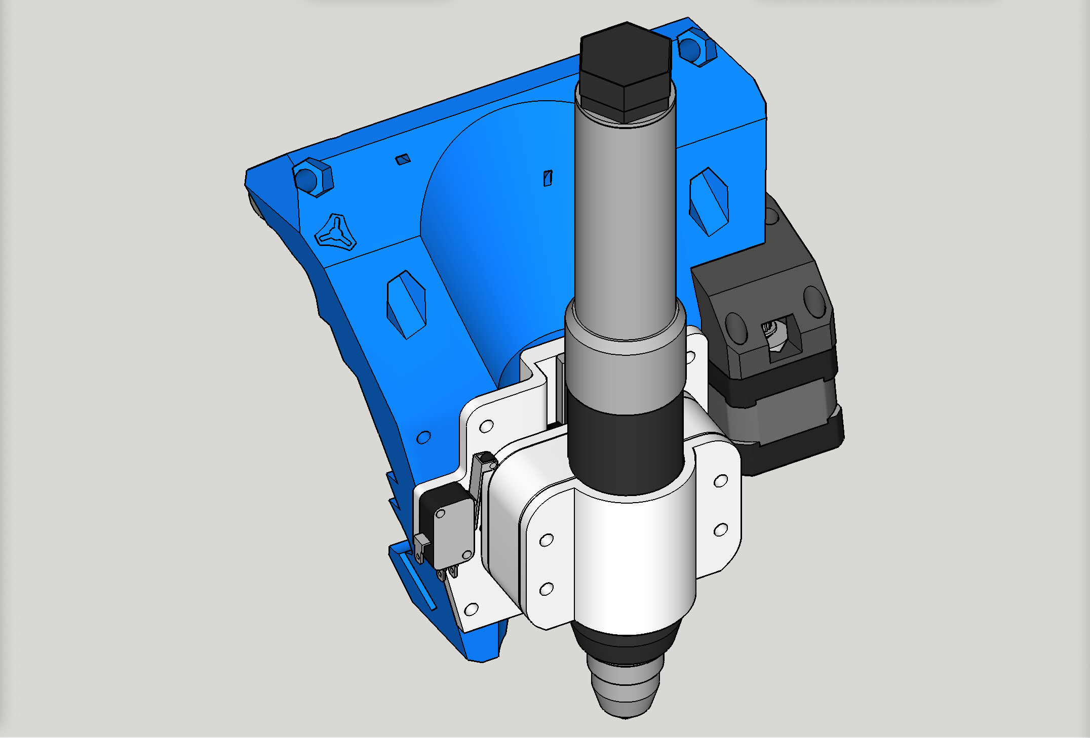
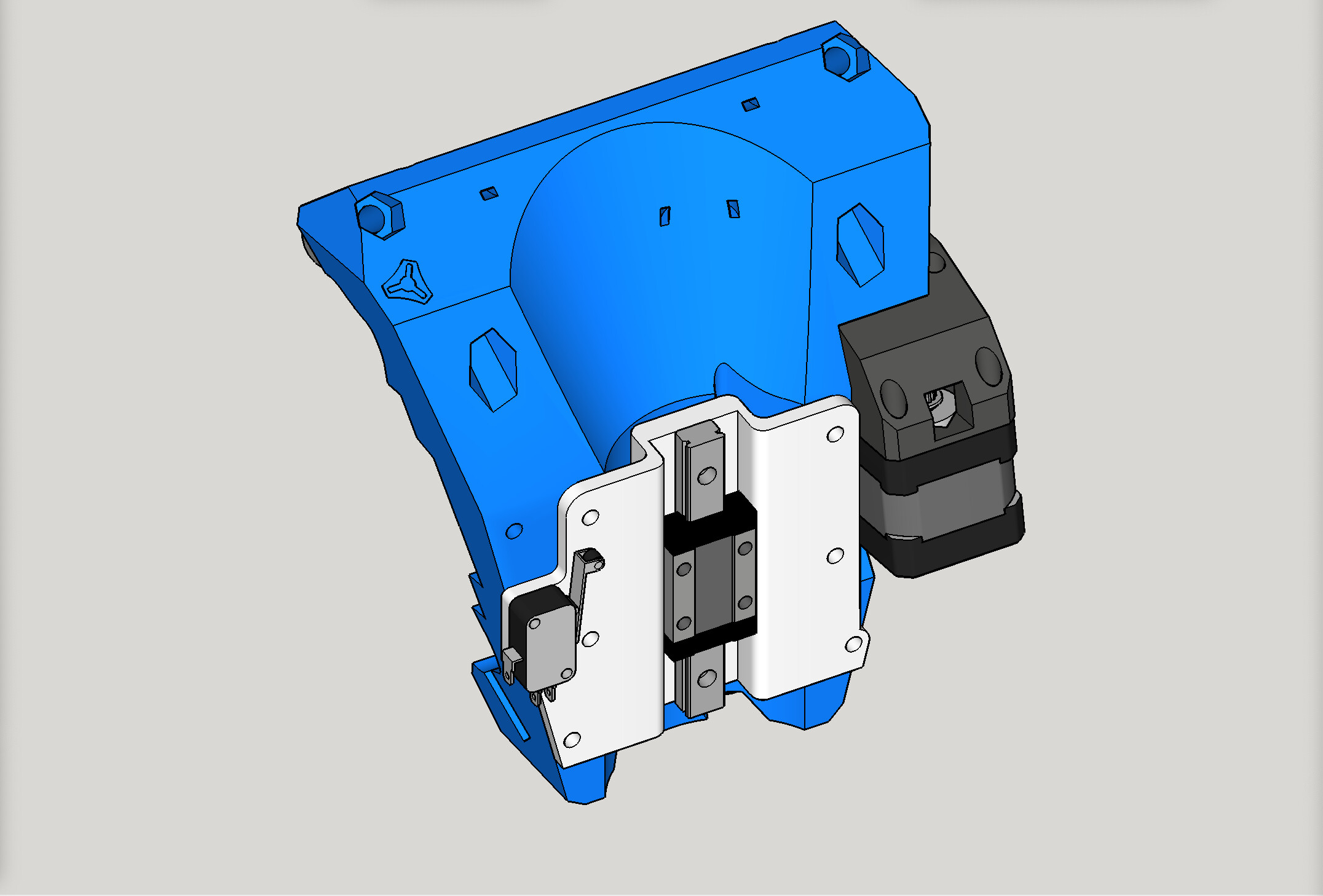
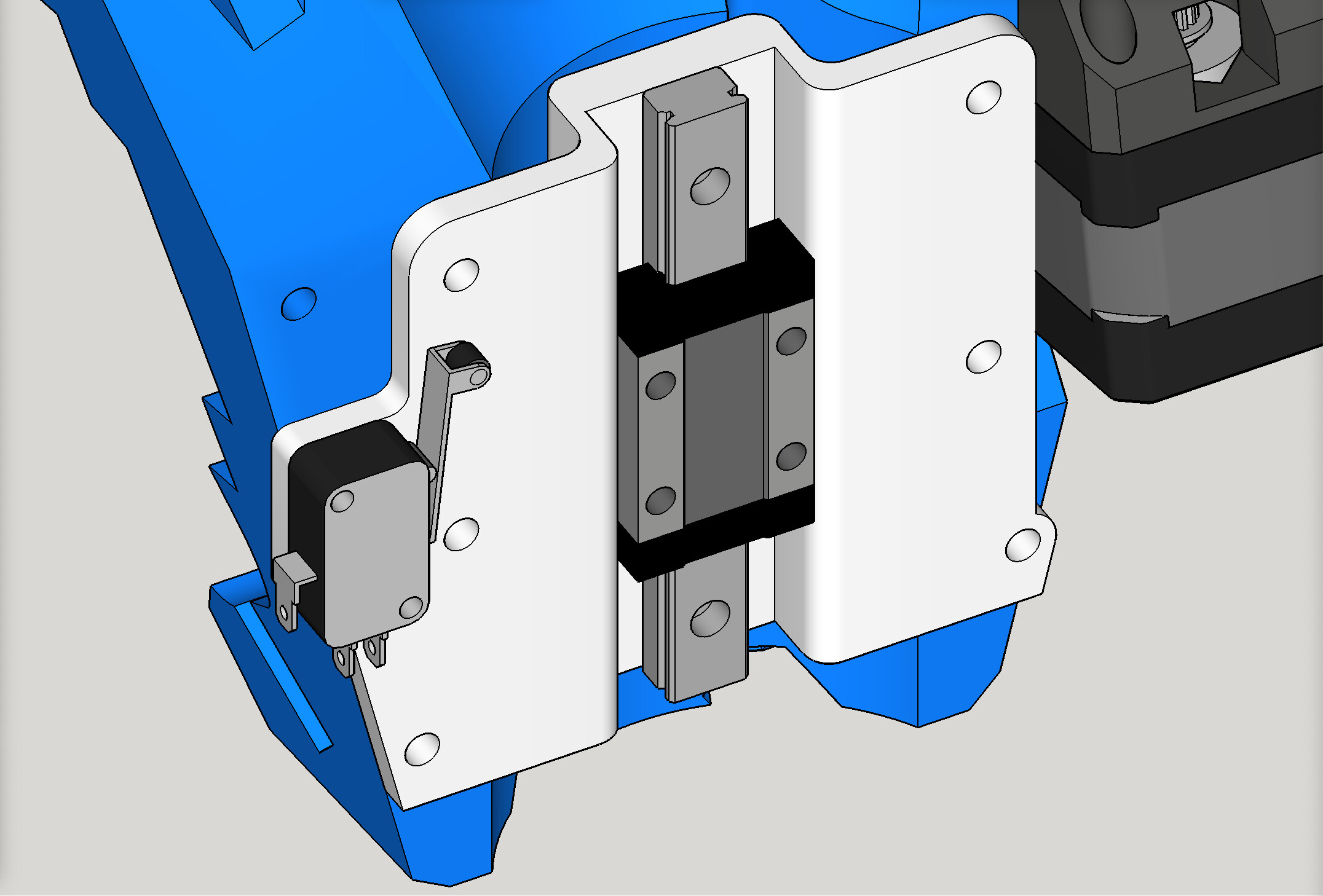
Regarding my design efforts toward a floating Z base for my 3D-printed machine torch mount, I’ve decided to go with a linear rod and slide bearing, that is just like the ones used for the YZ plates of the LowRider 3, except it only needs to be 100mm tall instead of 150mm (or 200mm in my case and other’s using @SupraGuy’s design for extended YZ plate).
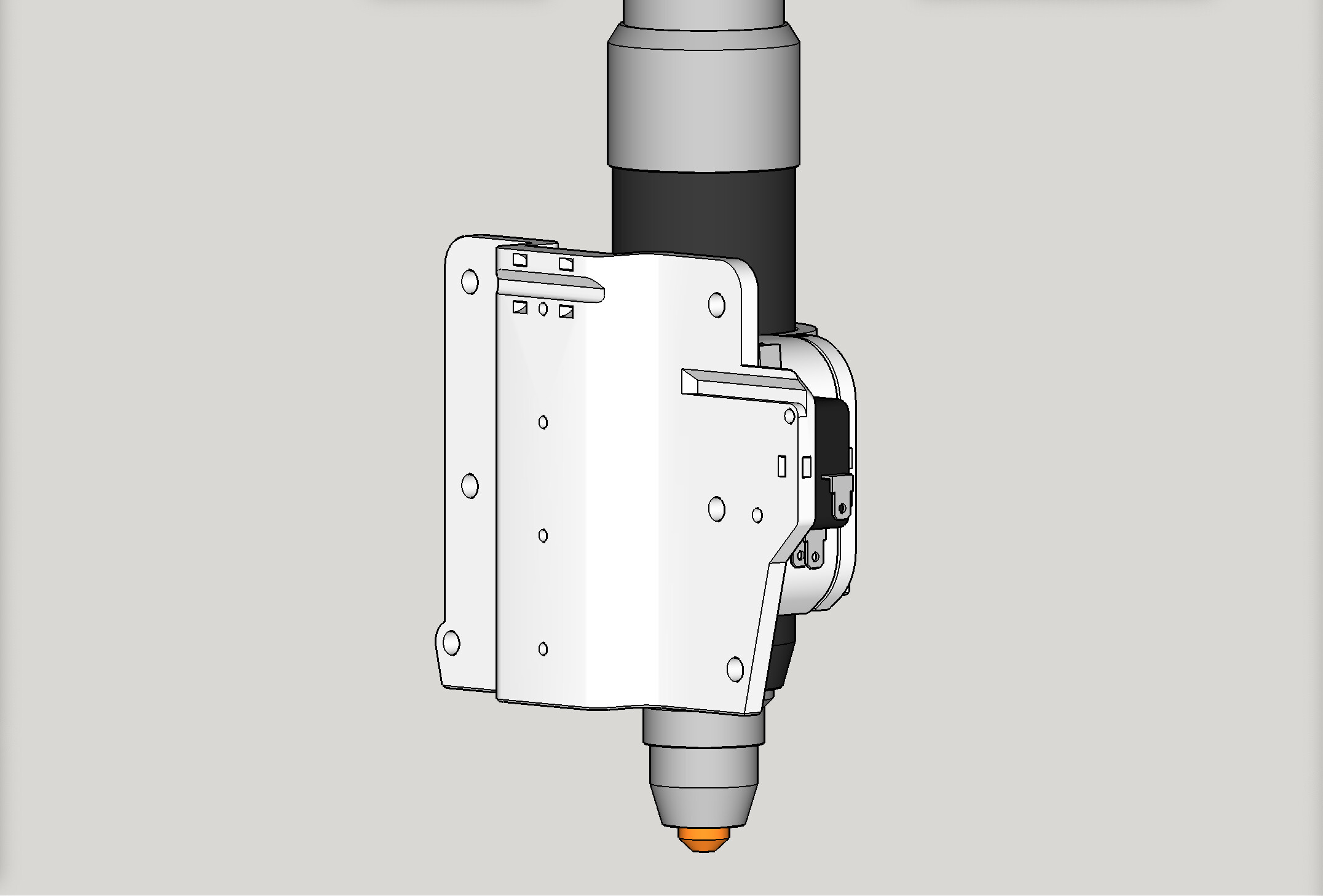
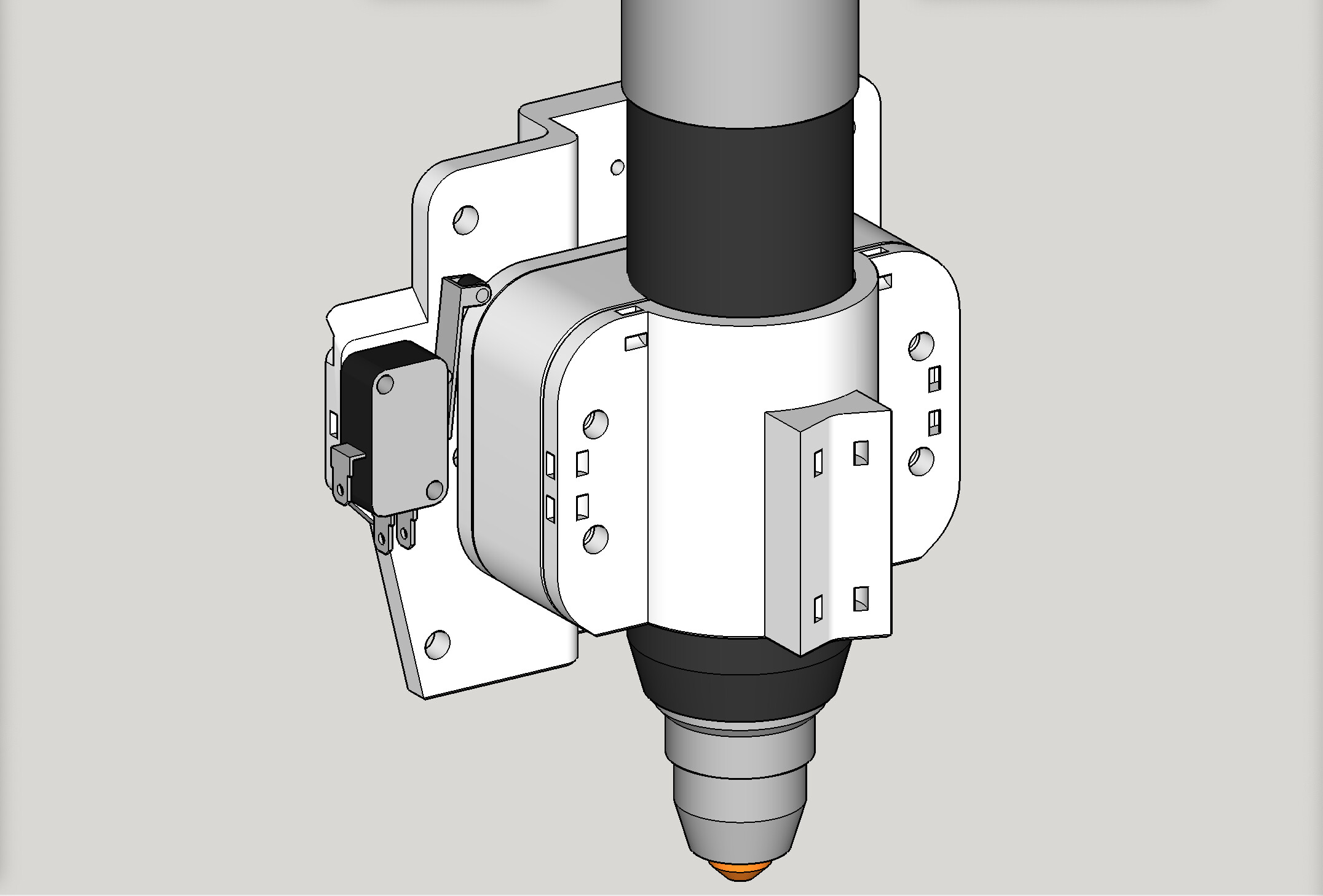
I’ve also decided to go with a magnetic break away feature, and then the question becomes how strong of an attraction is desirable and what magnets to use. I initially tried a design as shown in the attached images in which I used 12 of the slender “tab” style neodymium magnets, at 6 per side, and while the “star/clock hands” arrangement/configuration works well from a standpoint of self alignment, I don’t think the attraction is strong enough. The pounds of pull seem too low for the torch in hand. See more on that below the design pics.
The astute will notice that the design eventually includes a pen holder based on earlier designs remixes used for LR2 and LR3.
Again this design was done and printed, but I am redoing the magnetic breakaway for a different set of magnets.
I’m now working to alter the design to support use of a metal plate to be on one side, and on the other side two thick magnets that I just salvaged from an old PC hard disk drive, as seen in the image below. These magnets are exceedingly powerful, and with them I have the opposite concern, not too weak, but too strong. Their pull is so effective that the intended breakaway goal become a challenge as the torch tip could be damaged before the torch breakaway actually happens. So to mitigate this, I’m experimenting with how much printed plastic in a layer between the magnet and sheet metal, would be needed to reduce the pull to a more desirable range. The challenge on that end is that I’m trying to keep the thickness down as I had already drilled holes in my 1.5" square tubes based on a thinner design that did not include either floating Z or breakaway, and as this design is thicker, it’s offsetting my plasma tip from my table. I may have to drill and tap a new set of holes.
I realize that I need a limit of movement block at the top and bottom of the linear rod. Maybe just an exposed screw head on the linear rod at each end.
I started to think that maybe the linear rod does not need to be that long, however, as I studied the spacing between the holes in the rod compared to the size of the slide bearing, I realized even one less hole gives me no range of movement, and each added hole gives 25 mm of movement, so the rod is not longer than it needs to be, and instead the distance between holes gives a minimum range of use that is perhaps double what I really want, at 25mm as opposed to about 12mm.
Due to front clamp part also having the pen holder on it, I don’t think I could do a one piece clamp, as the slit for squeezing the one piece clamp would interfere with the pen holder. Unless you see something I’m missing.
It’s hard to tell by looking at the renderings but how much ‘stick out’ would a pen need to be able to reach the surface? I ask because if it is too long that would be problematic.
Being a magnetic breakaway mount talk about quick change! You could just print a dedicated magnetic pen holder and just swap out when needed.
Either way, you could always slide the pen holder to the side, or the slit to the side, or both.
Ultimately what you’ve already come up with is pretty damn slick so don’t pay too much attention to me.
QTPlasmac provides for air scribe, zeroing lasers, and even tool PoV camera functionality, have you thought about incorporating any of that down the road?
[edit] On second thought, an air scribe on a magnetic mount is probably asking for trouble… I suppose all this peripherals would have to somehow be crammed into the non-breakaway part of the mount.
@kd2018
Thanks for the great thoughts and advice! The idea of the dedicated magnetic pen mount is cool, although I’d have to do the work to generate it. Conventional wisdom might say that creating the metal strips of the right shape is easier than salvaging more magnets, but for me it was the other way around. I located the metal strips on the secured side and put the magnets on the removable side. Processing by cutting metal with the bandsaw was required for both the magnets and the strips. Of course once I get the CNC plasma working, I could easily cut the strips in that shape. Maybe then I will reprint and flip the magnets onto the secured side and put the metal strips on the removable side. The bandsaw work on shaping sheet metal to match the shape of the magnets was harder and more risky than processing the magnets. If I could locate another old PC hard drive I could get another set of those strong magnets, for whatever.
I think I will be ok on the pen holder re. stick-out. Will know for sure once I get it running.
Following with interest, I’m planning on a floating mount for my LR3 plasma but it’ll need to fit a hand held torch rather than straight machine torch like you have.
I posted the “Part 1” video about 3 weeks ago. Sorry for delay, between then and now. Here as promised is the “Part 2” video on getting the plasma torch mount with floating Z setup:
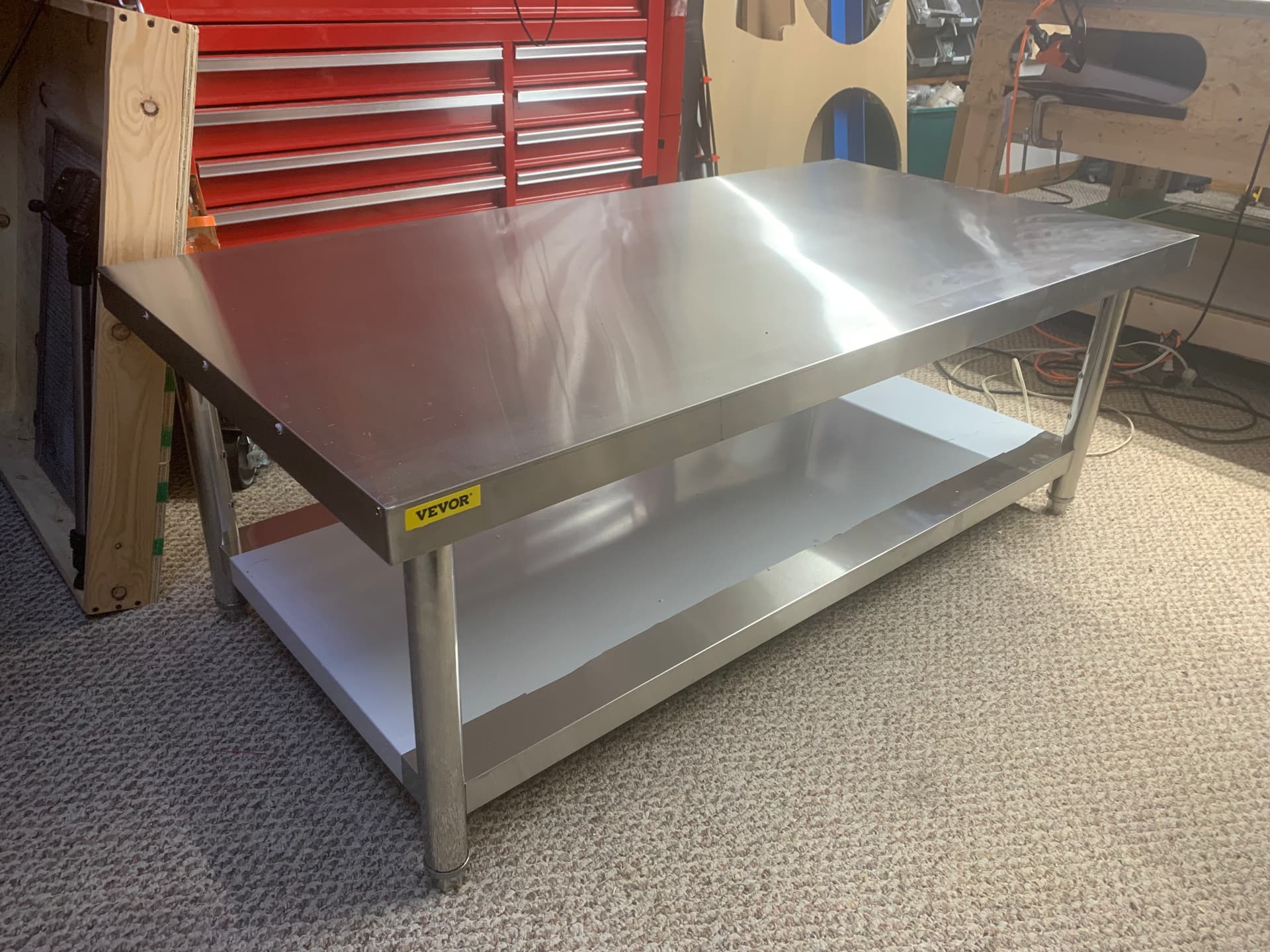
I need to rearrange my workshop to better use the space and to make room for the plasma cutting table! I had been delaying that but I’m headed into it. I actually plan to make a portable assembly table
out of the 4x8 previous “base” “shelf” that was under the LowRider table (previous version). I’ve been trying to decide whether to leave it whole and add legs and casters, or cut it down the middle and stack it on itself, with legs and casters, to make a long, half-wide double decker.