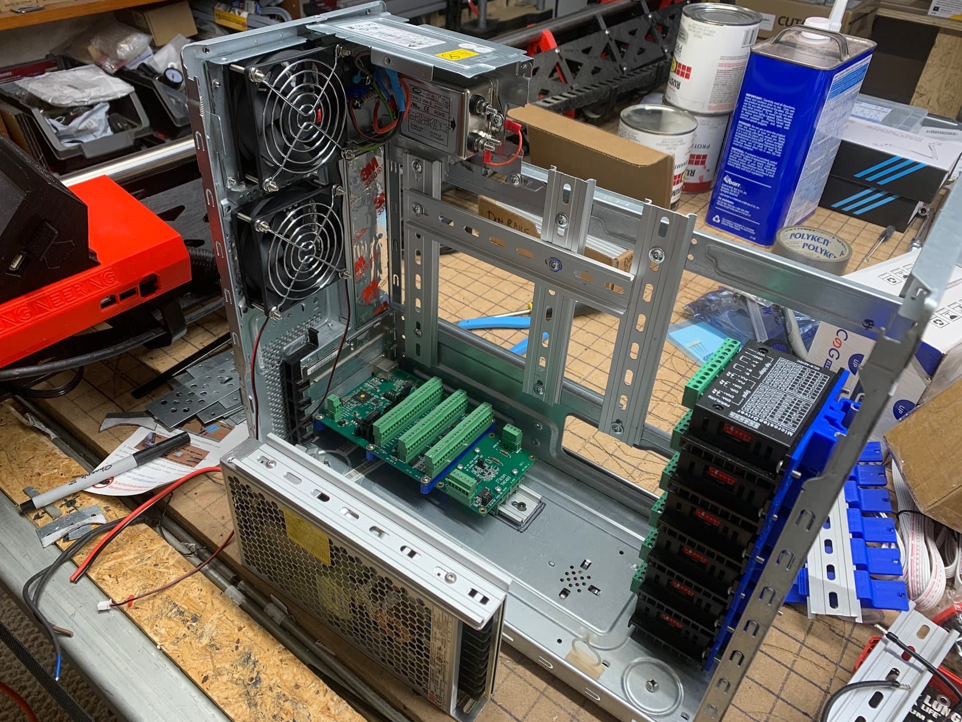
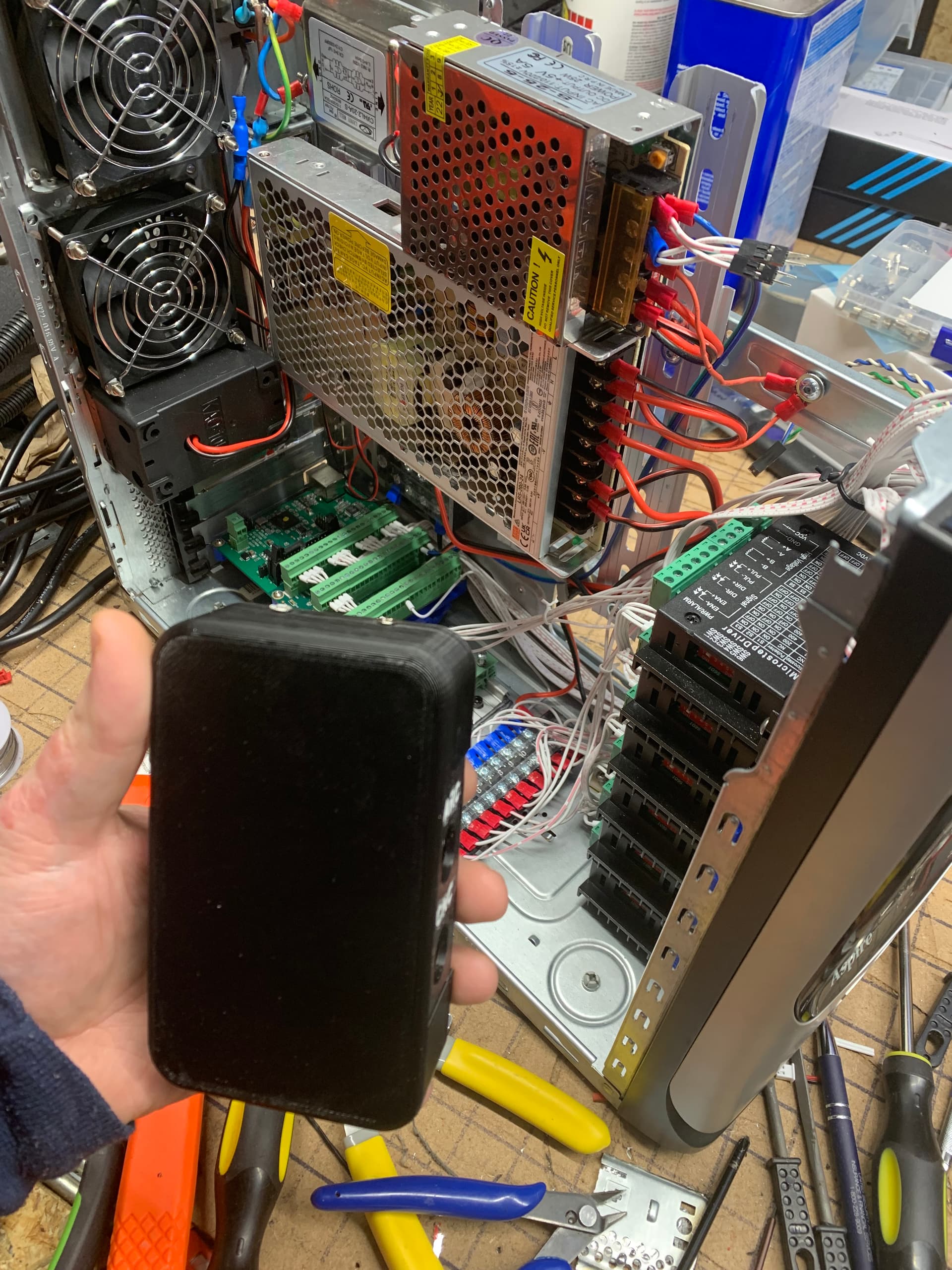
Another micro update. More progress on my control box. Now have the 13 A fast blow fuse, EFI filter, 5 V power supply, 24 V power supply, two cooling fans, both of the Mesa parts, which consists of a control board and a THC board, and all of my stepper motor drivers in place, but I still need to run the wires within the board. Beyond that my next task on this control box will be generating a panel for the front that will have aviation style connectors for the various wires that need to communicate to the plasma cutting table. I have not been able to sink a lot of time into working on this which is why it has been delayed and progress is slow.
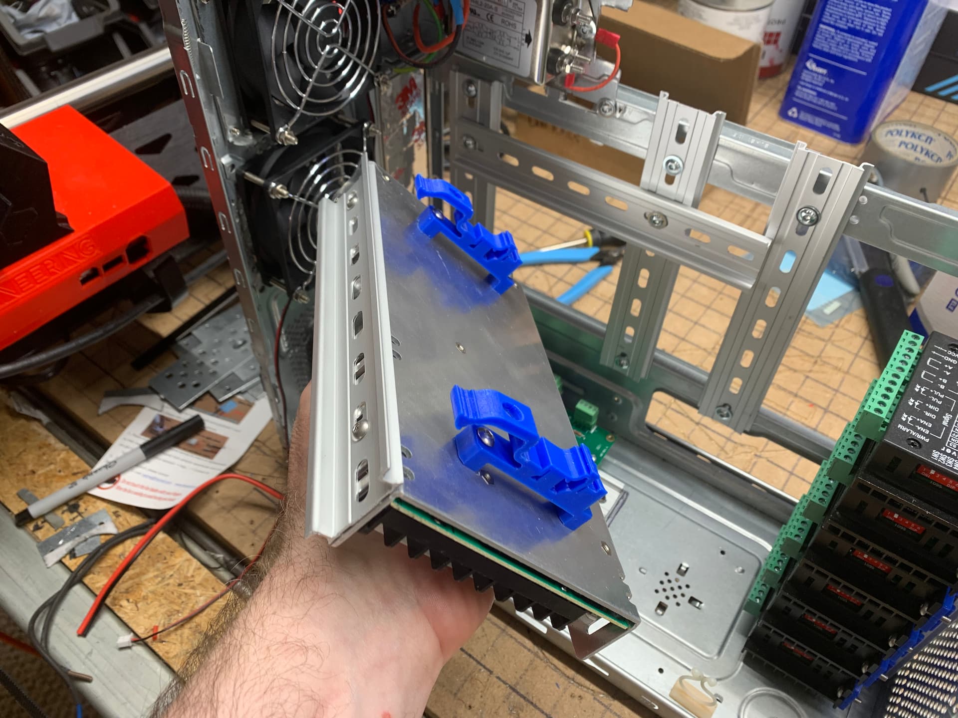
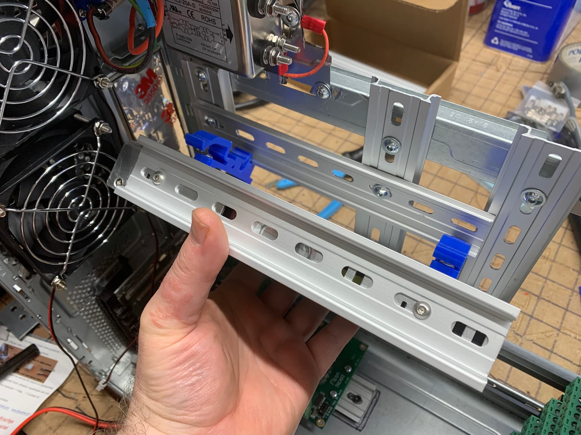
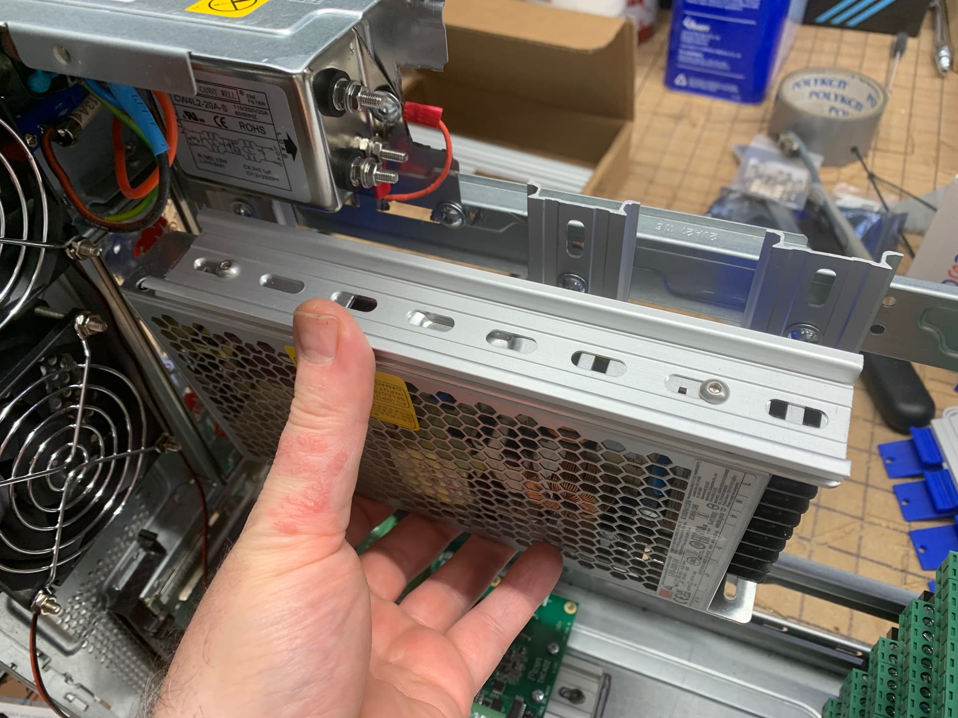
PS: Photos below show a DIN rail mounted on the larger power supply, but in the end I did not use that because it added too much height on the other power supply.
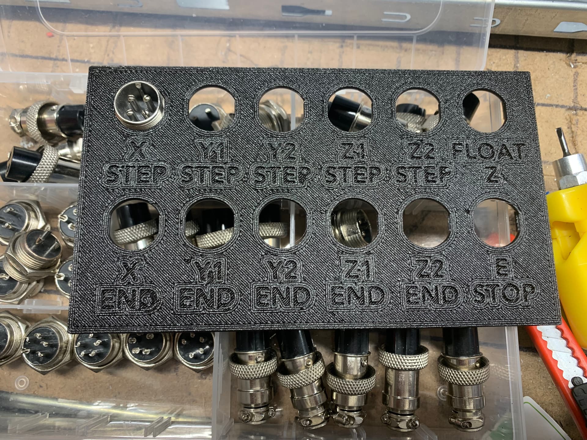
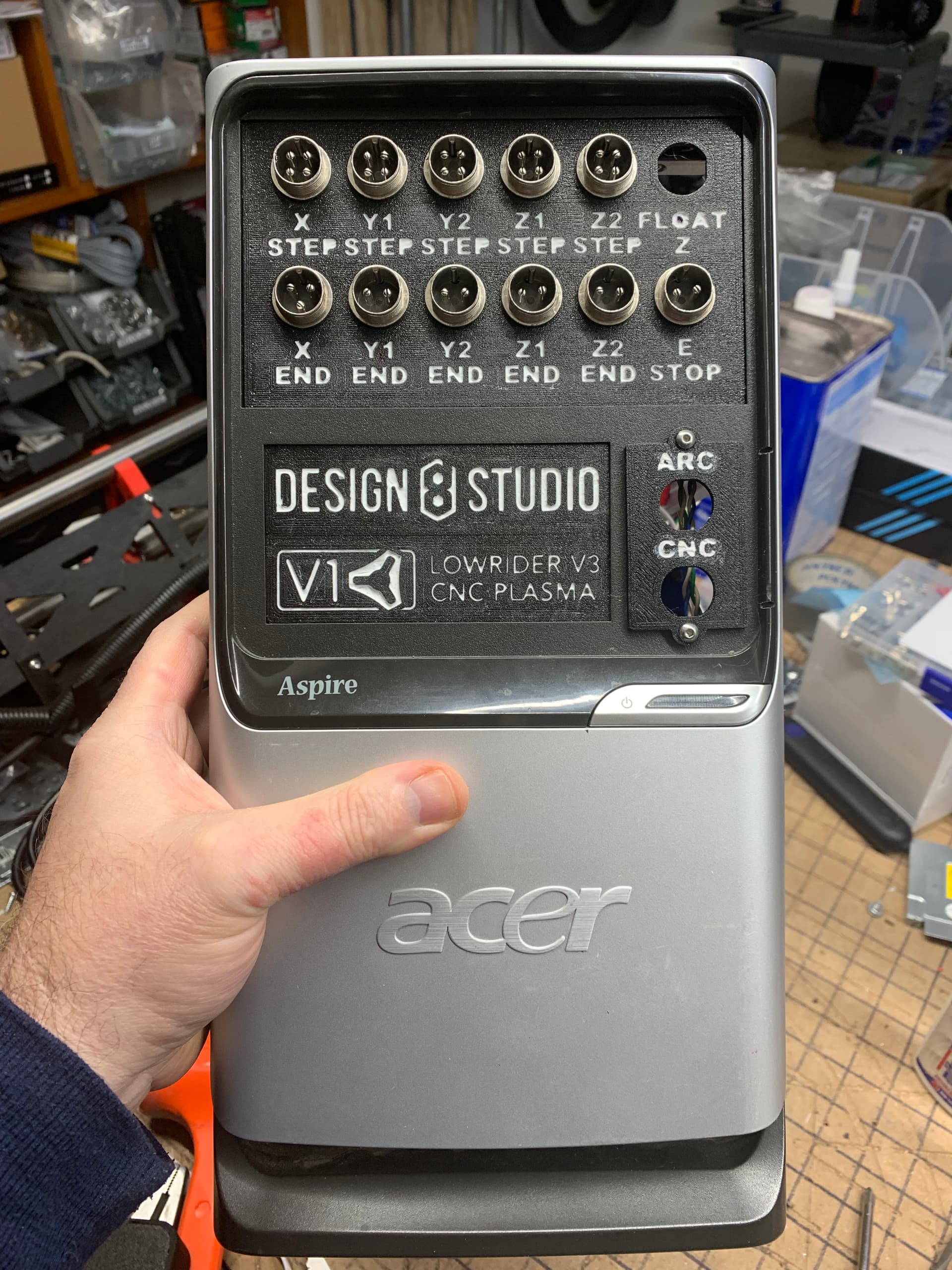
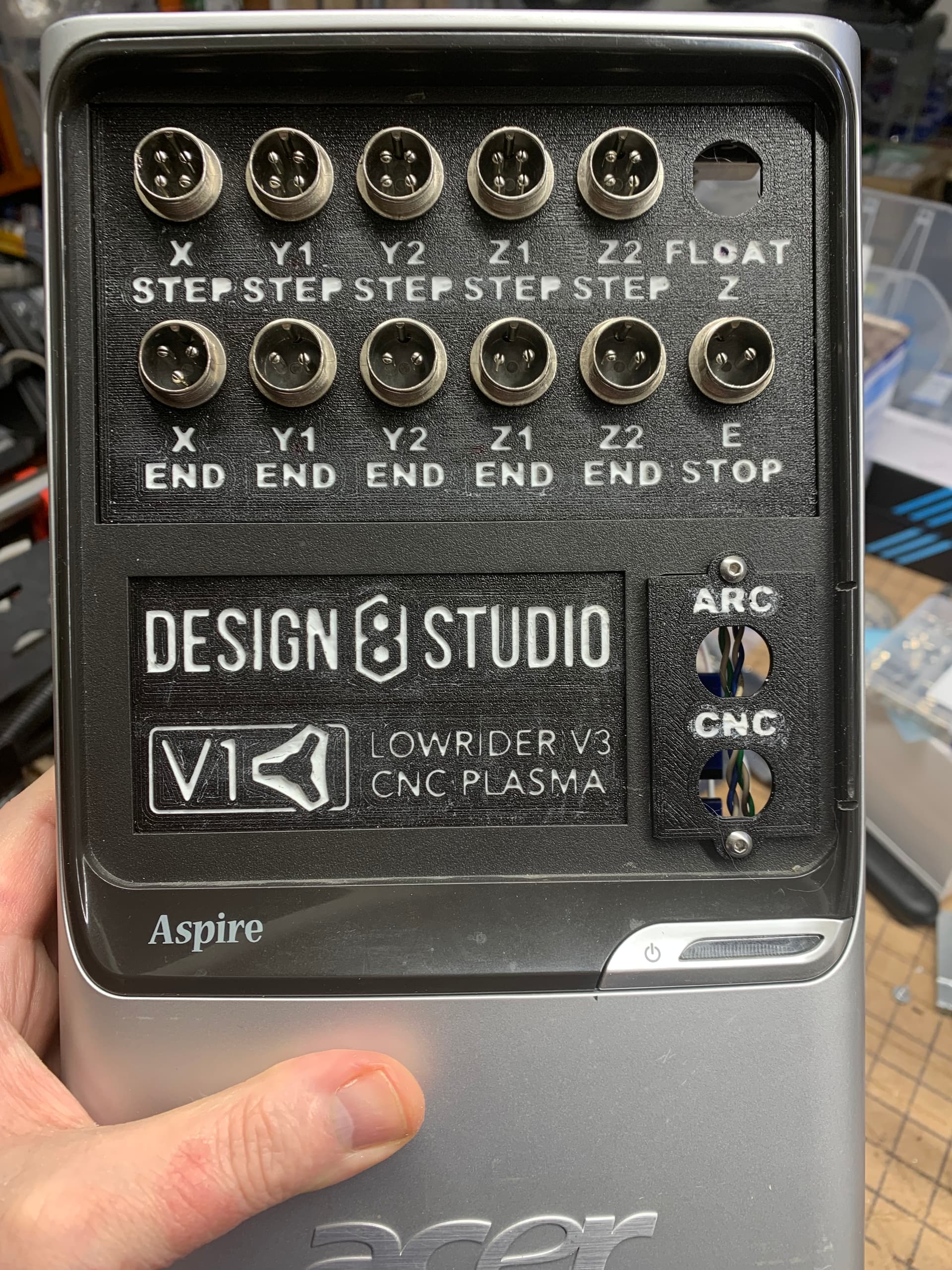
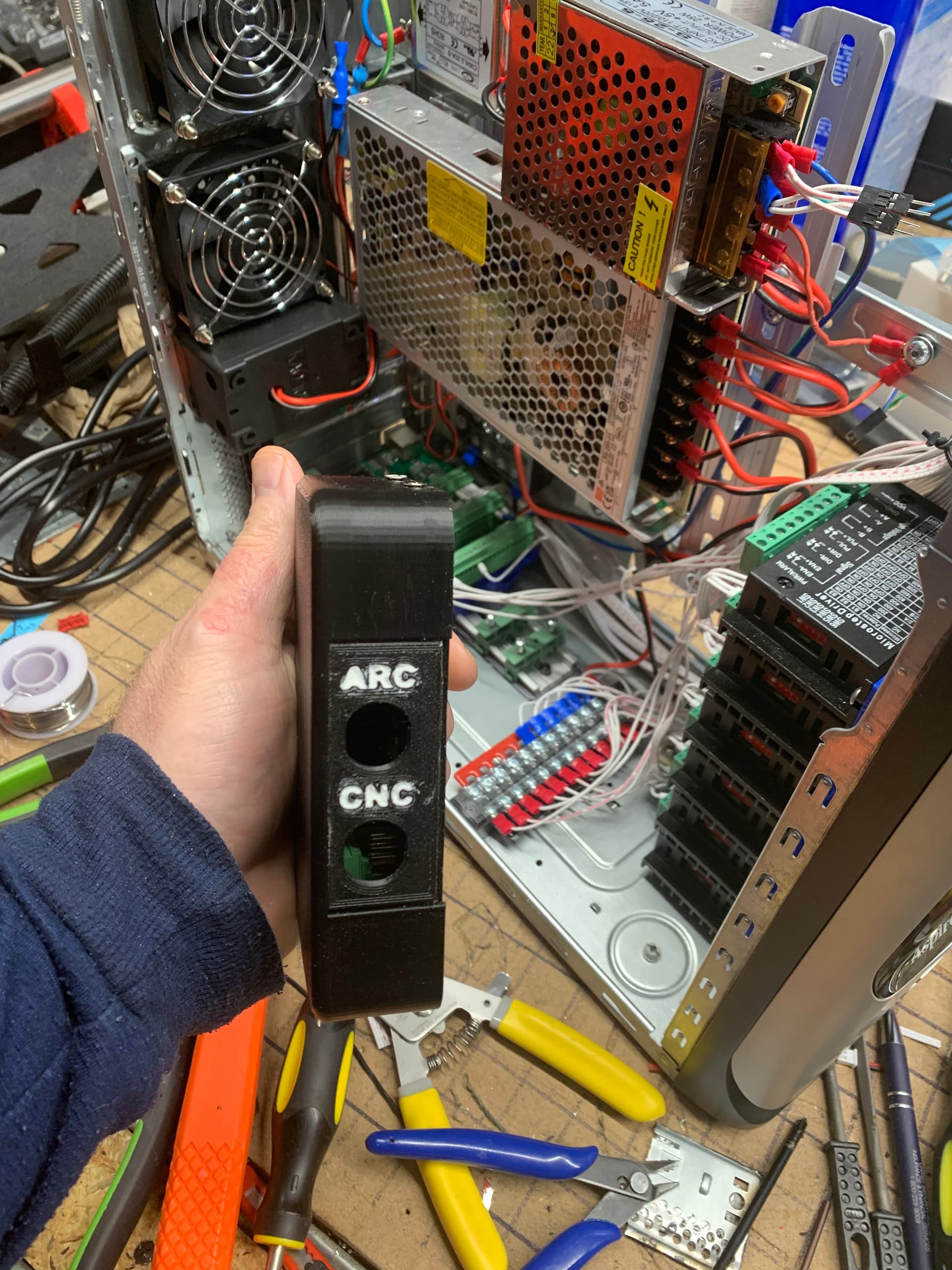
That’s are really nice print. I’d fill the writing with something white (paint pen, nail polish, white-out, etc.) for ease of reading.
If you’re relying on the metal outer shells of those connectors for bonding or grounding, you may want to add a strip of aluminum tape (commonly used for hvac ducting) on the back of your 3D printed plate so that it can be bonded to the rest of your system. Doing this helped with maintaining shielding on my cables into my plastic enclosure.
My plan on the white lettering is to use the silicone method described here:
Re. aluminum tape
I have some and had already been using it to plug holes in the old PC tower case I’m using, so the cooling fans would be more effective. Seems easy enough to do. My metal case is itself grounded. Power supplies and EFI filter are grounded as well.
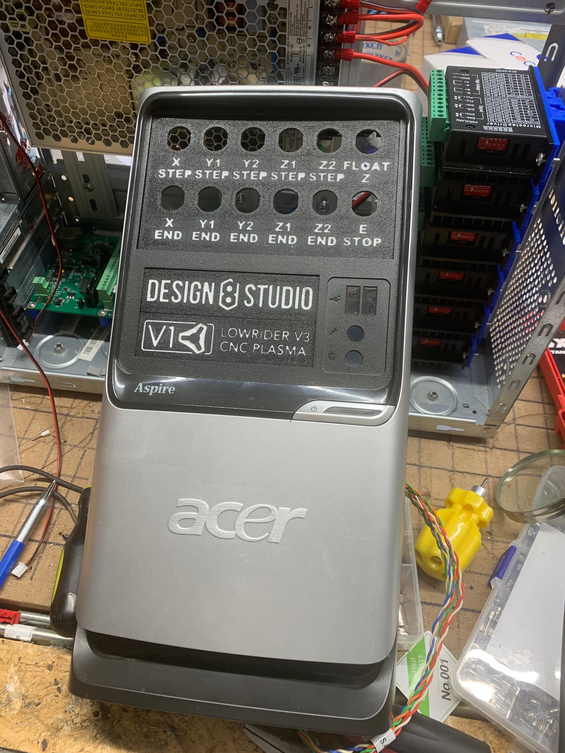
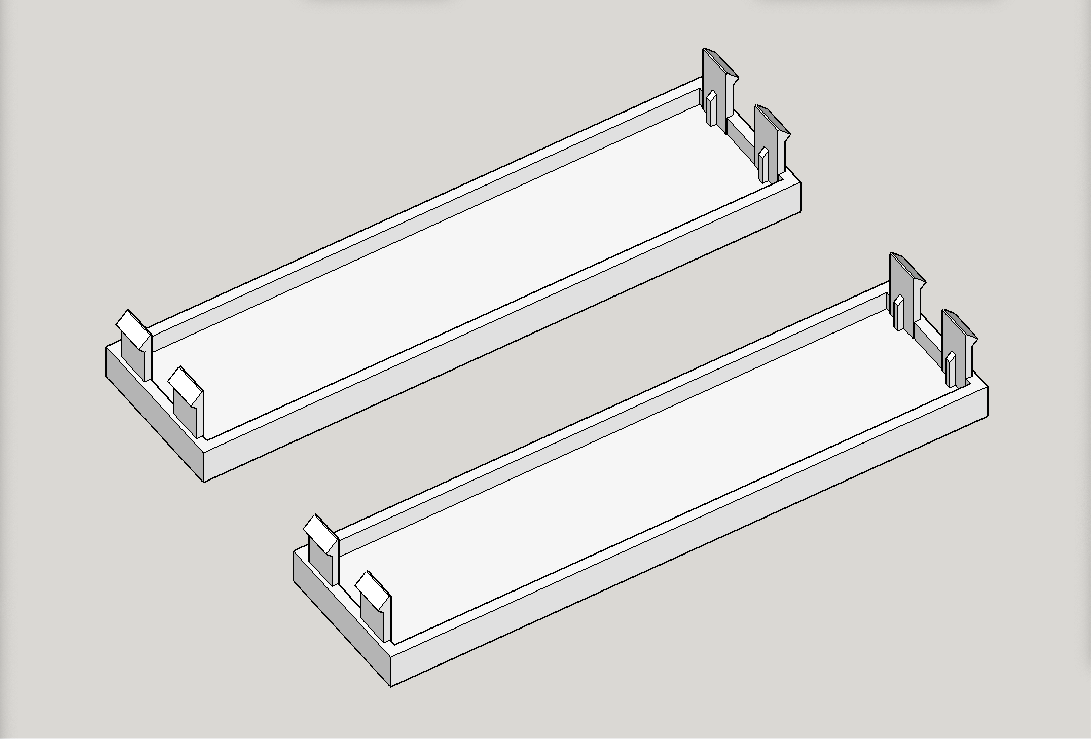
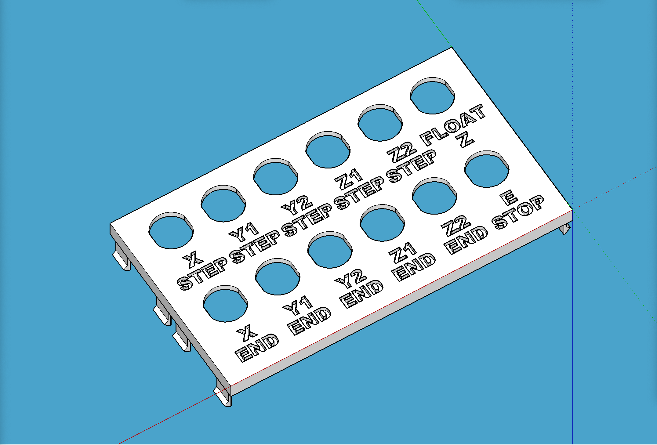
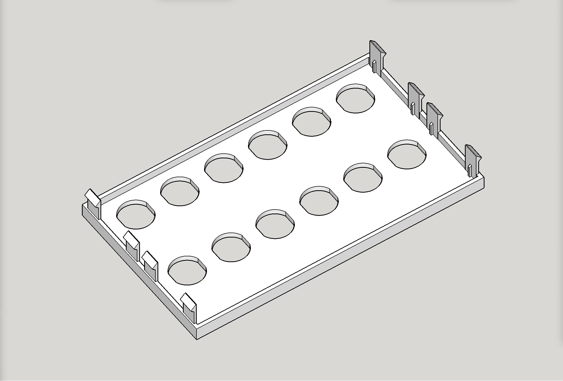
I gutted an old desktop PC tower for the control box for the CNC plasma I’m building, which is based off of the V1 Engineering LowRider v3 for its motion control system. I custom designed printable replacements for the plastic covers over the bays where the CD-ROMs and disk drives used to go, in order to position aviation-style quick connectors for the various wires for stepper motors, endstops, etc.
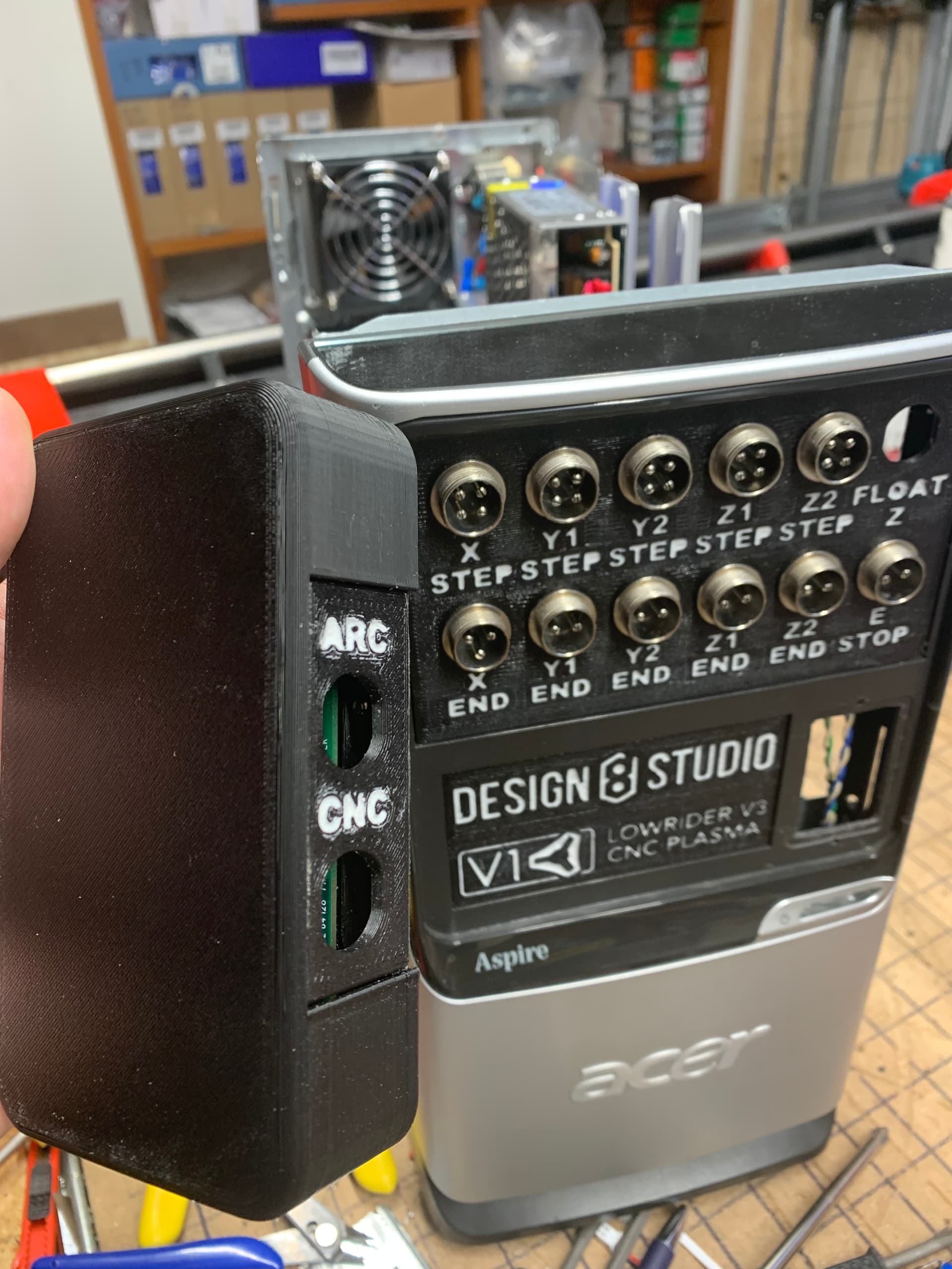
Note: the holes for the aviation-style quick connectors are not completely round, but rather are what are commonly called “double-d” holes, with sides lopped off to match the connectors. It is intended to keep the connectors from spinning once installed.
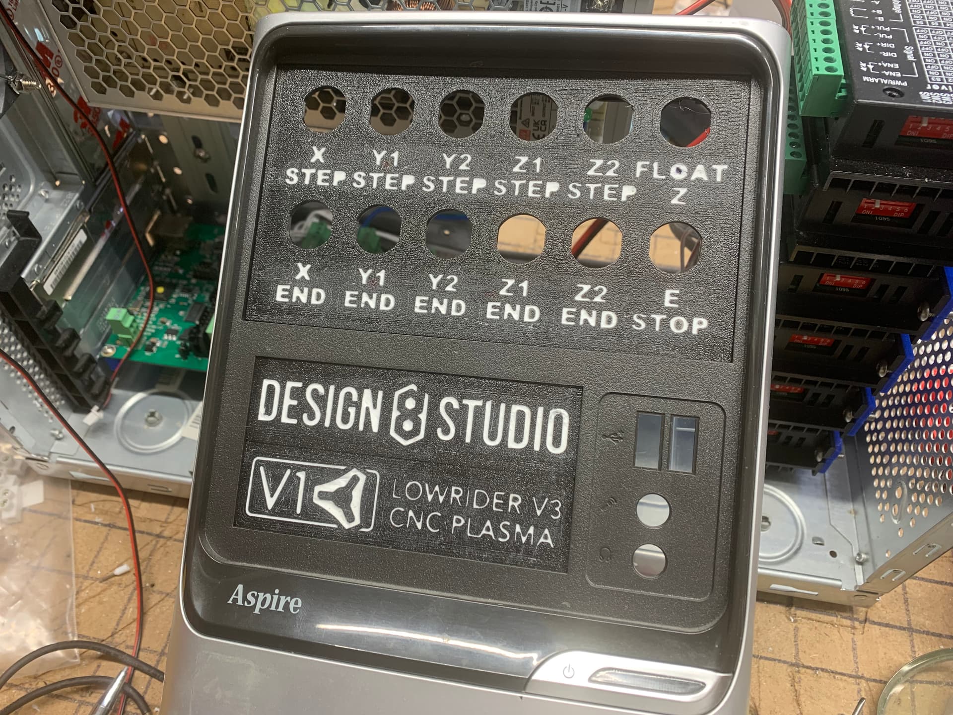
My white “inlays” for lettering (labels, etc) and graphics were done using essentially the method shown in the video below, except I used caulk that was a silcone-acrylic mix, and it was “quick dry” (took only 20 minutes to dry, instead of 24 hours!) so my project work was completed much sooner than shown in the video.
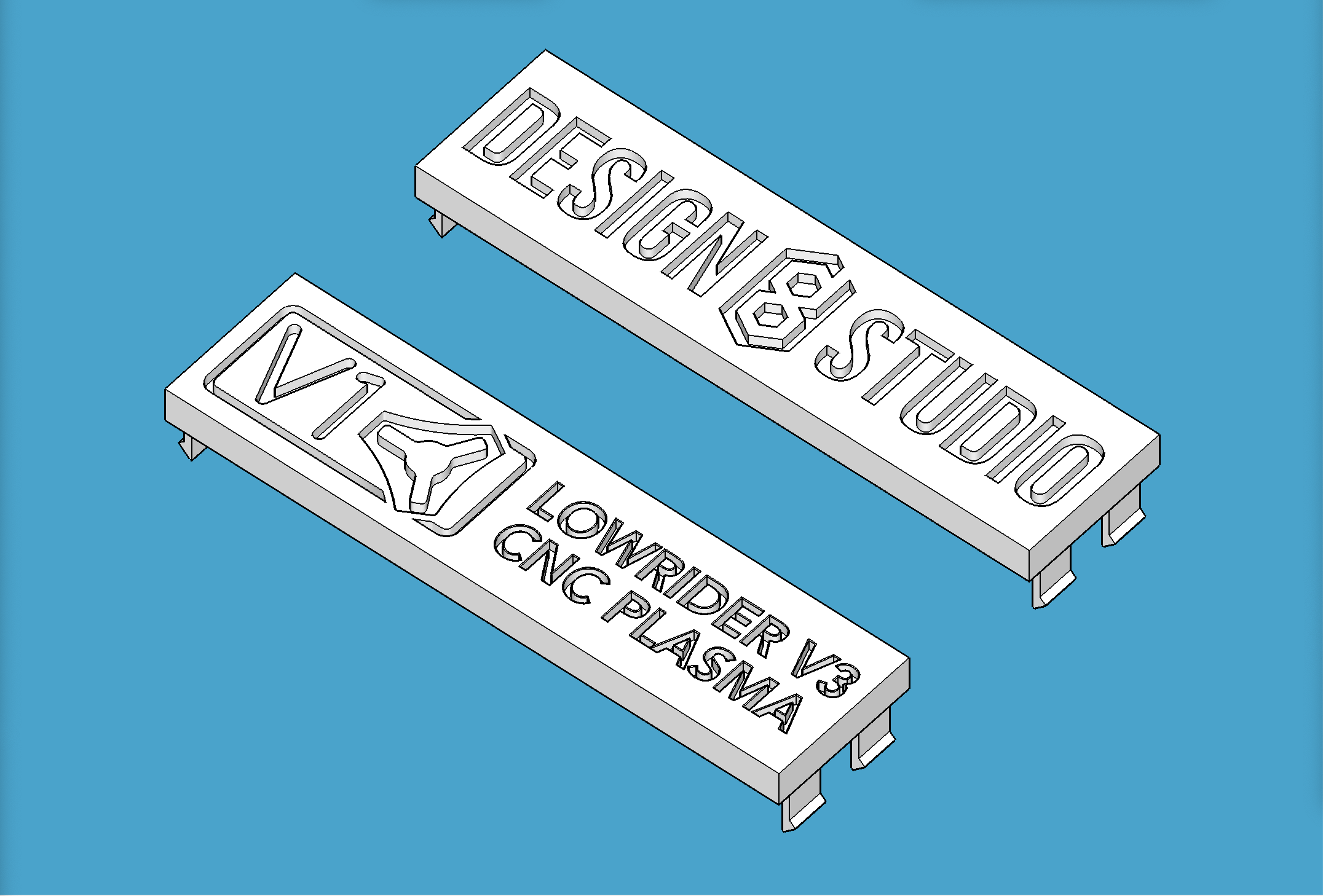
If you should ever happen to want to reuse an old PC tower and you want to redo/redesign the plastic covers for its bays, you could do a lot worse than remixing or otherwise reusing my work here.
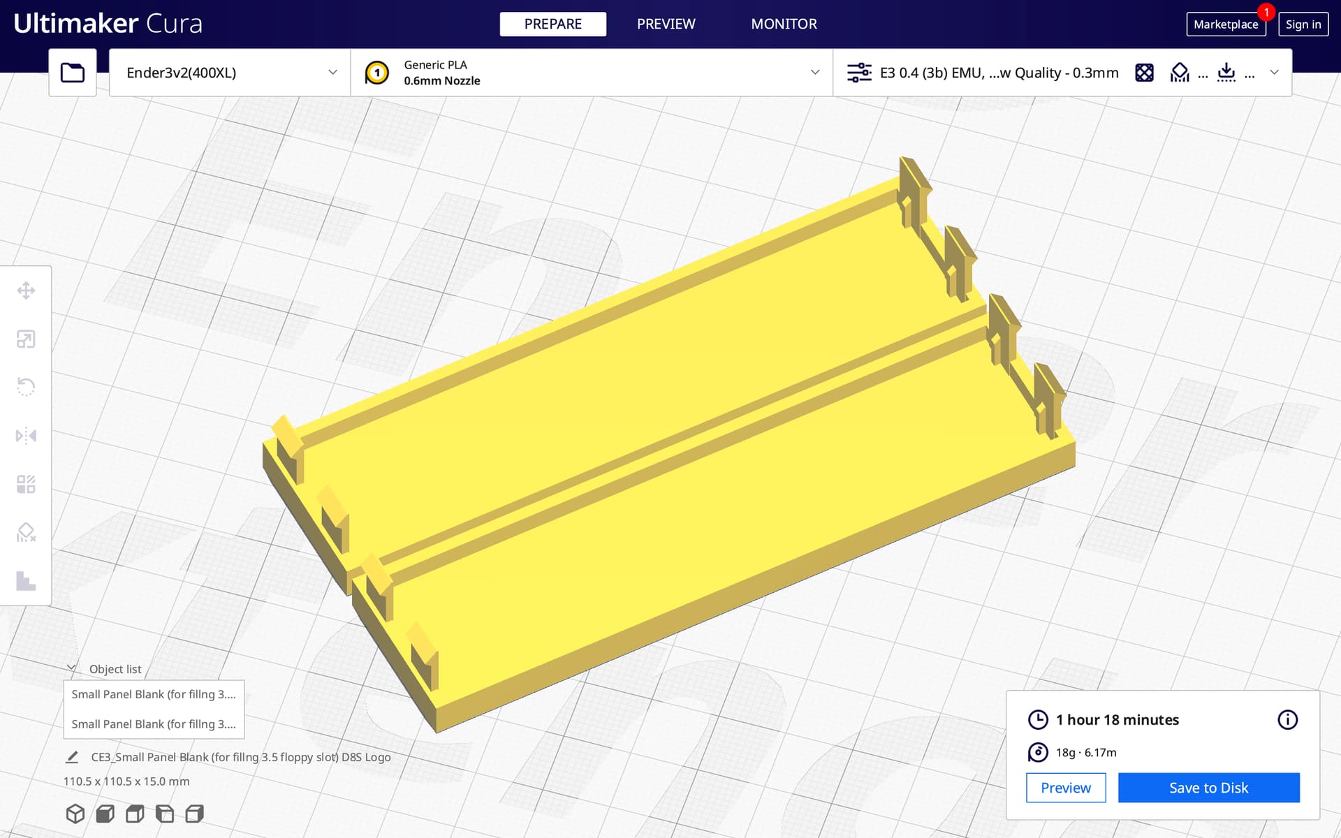
I’m also including a “blank” version of the smaller plastic cover (for bays that used to hold what we called 3.5" floppy drives).
Print details:
Prints without supports
Filament: PLA
Nozzle diameter: can be either 0.4 or 0.6 mm. I used 0.6.
Layer Height: 0.3 mm
Wall thickness: 0.6 mm
Number of perimeter walls: 2
Number of top/bottom layers: 3
Infill: 20%
Print as oriented*
My print notes:
I printed as oriented with only one exception: I also rotated my prints by 45% so the layer lines would be straight across and straight up and down instead of on 45% angles.
This was printed on a heavily modified Ender 3v2 (modified with Ender Extender 400 XL, board and touch screen replaced with BTT items, and the extruder and hotend replaced with MicroSwiss direct drive extruder and all-metal hotend).
White inlay lettering details:
For prepping the prints before the caulk inlay, to protect the panel from caulk sticking everywhere, I used whatever dish detergent we had in our kitchen. It was blue.
I used this caulk (see link) but bought it at Walmart instead of Amazon as the price that way was lower: https://amzn.to/3G8wuDu (DAP brand “Alex Fast Dry” 5.5 oz white caulk)
This caulk dries much quicker than shown in the video, and I was able to get done super quickly. Highly recommend this approach. Worked great!
Change log:
December 21, 2022, 5:10 am (EST): initial posting of v1.0.0
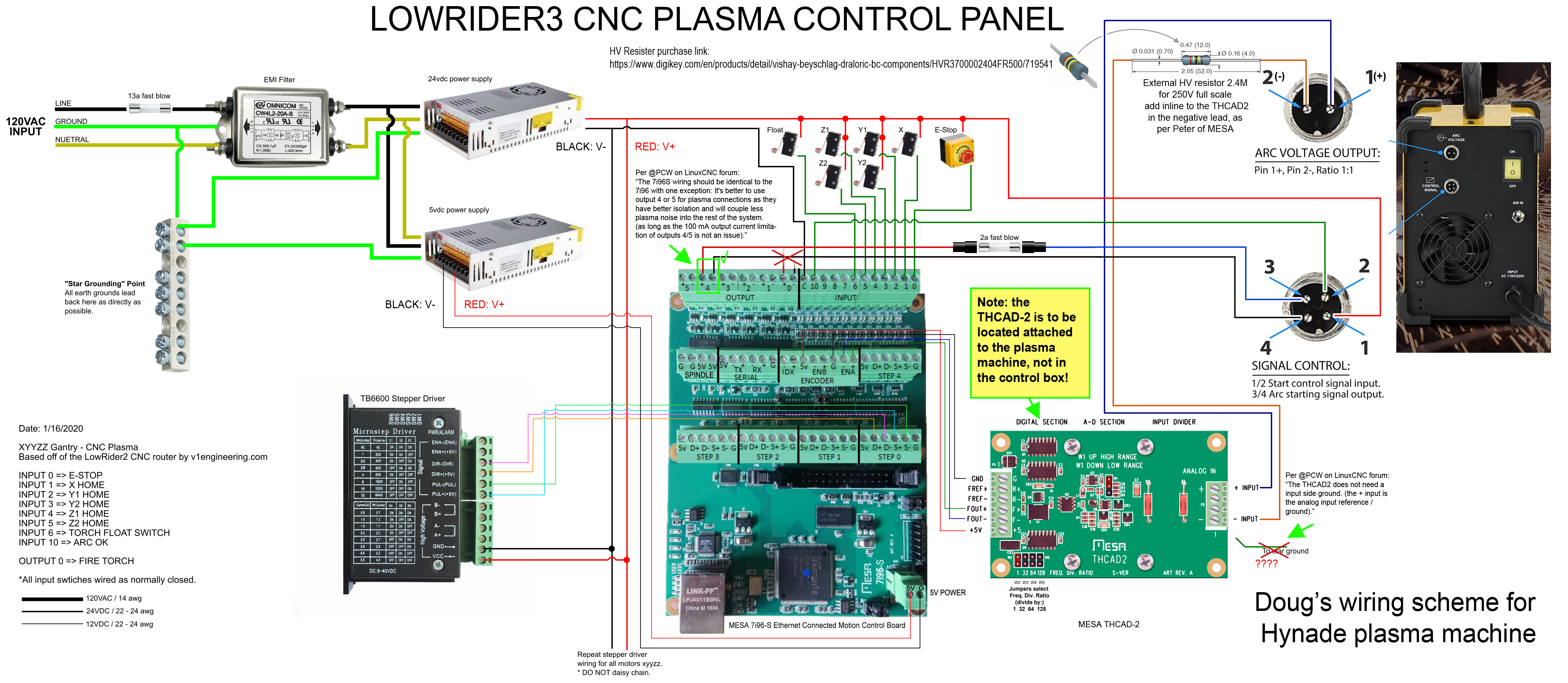
Here is my proposed wiring schematic, which is a revised version of the wonderful plan shared by @kd2018 for his plasma control panel:
UPDATE 2022-12-26: Corrected the graphic to reflect that I am using THCAD-2 instead of THCAD-10.
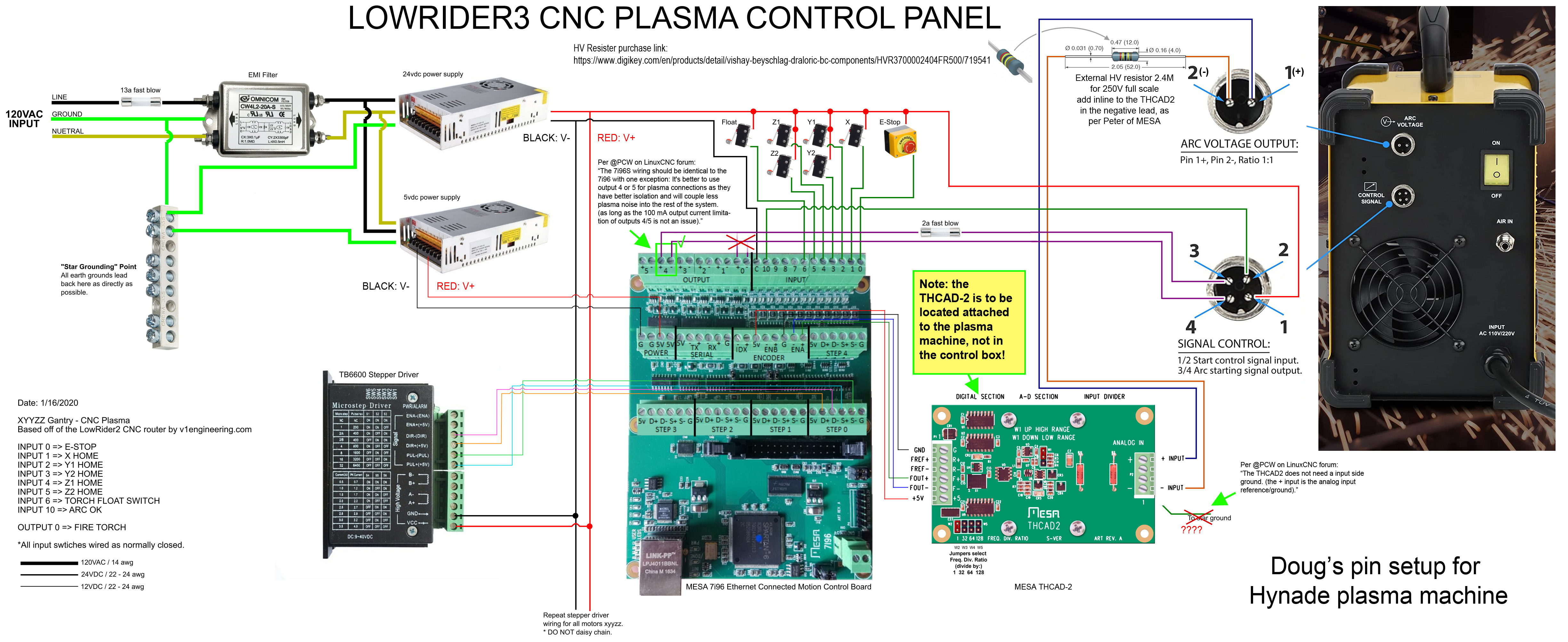
UPDATE 2022-12-26 - B: Corrected the graphic again to reflect tweaks based on input from LinuxCNC forum answers, re. THCAD-2 grounding (no) & placement (on plasma machine), and re. 7i96S (switching “Torch On” from output 0 (-/+) to output 4 (-/+).
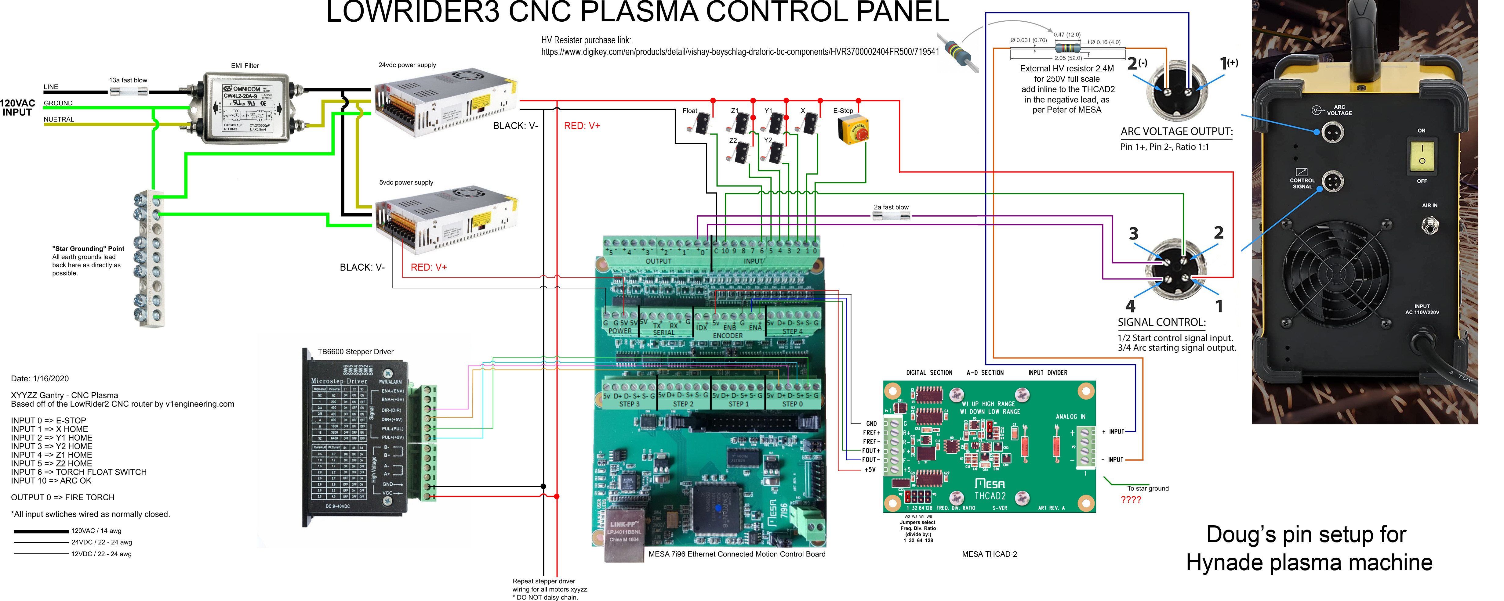
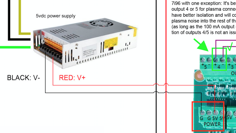
UPDATE 2023-01-23 - A: Corrected the graphic again to reflect that my control board is a 7i96S instead of a 7i96. This also included reflecting on the wiring diagram that the 5v power supply wires go into the back right corner — as the former location used on a non-S version is now (on the S version) for control of spindles.
Hey, my wiring schematic is 5869 x 1970 pixels, but when I upload it, it gets downsampled to 1920 x 644.
I’m not asking for modification to the site to prevent this, just asking if there is a built in way to prevent it, or should I seek to host the image in full resolution on one of my sites and just link to it here?
UPDATE: Please disregard. I just uploaded it to my own site, and then linked to it in my post above.
UPDATE 2: After I had uploaded it to my own site, and then linked to it in my post above, the system here at V1E forum site automatically cached a copy at full resolution and edited the post to display it! So I found the work-around for this issue!
I posted the following questions over on the LinuxCNC form, but I’m adding them here in case it helps with getting an answer…
Quote:
Hello and thanks for being so awesome. Hope you all had a merry Christmas.
I’m building a CNC plasma based on the LowRider v3 motion control system, guided by a previous build by Kyle (@kd2018 at the V1E forum) which was based on the LowRider v2 motion control system.
Kyle had shared an immensely helpful wiring diagram image, which I have copied and tweaked to match my specifics (somewhat).
Where Kyle used MESA THCAD-10 … mine is THCAD-2. His diagram calls for grounding (“to star ground”) from the analog ARC input area of the THCAD-10. See below. However, according to the manual for THCAD-2, the two center connections (other than + and -) are “unused” — do I need to find some way to ground via somewhere else? Or can I ignore that part?
Where Kyle used MESA 7i96 mine is 7i96S. I do not know if this requires any changes. See below. ??
Below are Kyle’s original diagram and my tweaked version.
That is good to know. You are going to keep the HV at the torch and mount that card externally on the plasma? That sounds pretty good to me. Interesting about the ripple , that is all new stuff to me.
UPDATE 2022-12-26 - B: Corrected the graphic again to reflect tweaks based on input from LinuxCNC forum answers, re. THCAD-2 extra grounding (no) & placement (on plasma machine, not control box), and re. 7i96S (switching from output 0 (-/+) to output 4 (-/+).
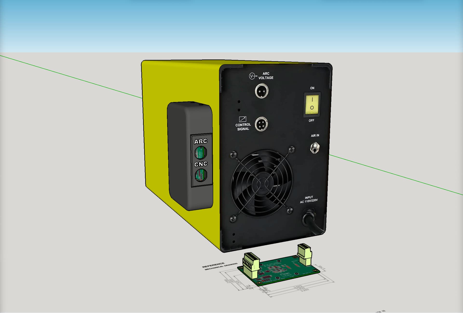
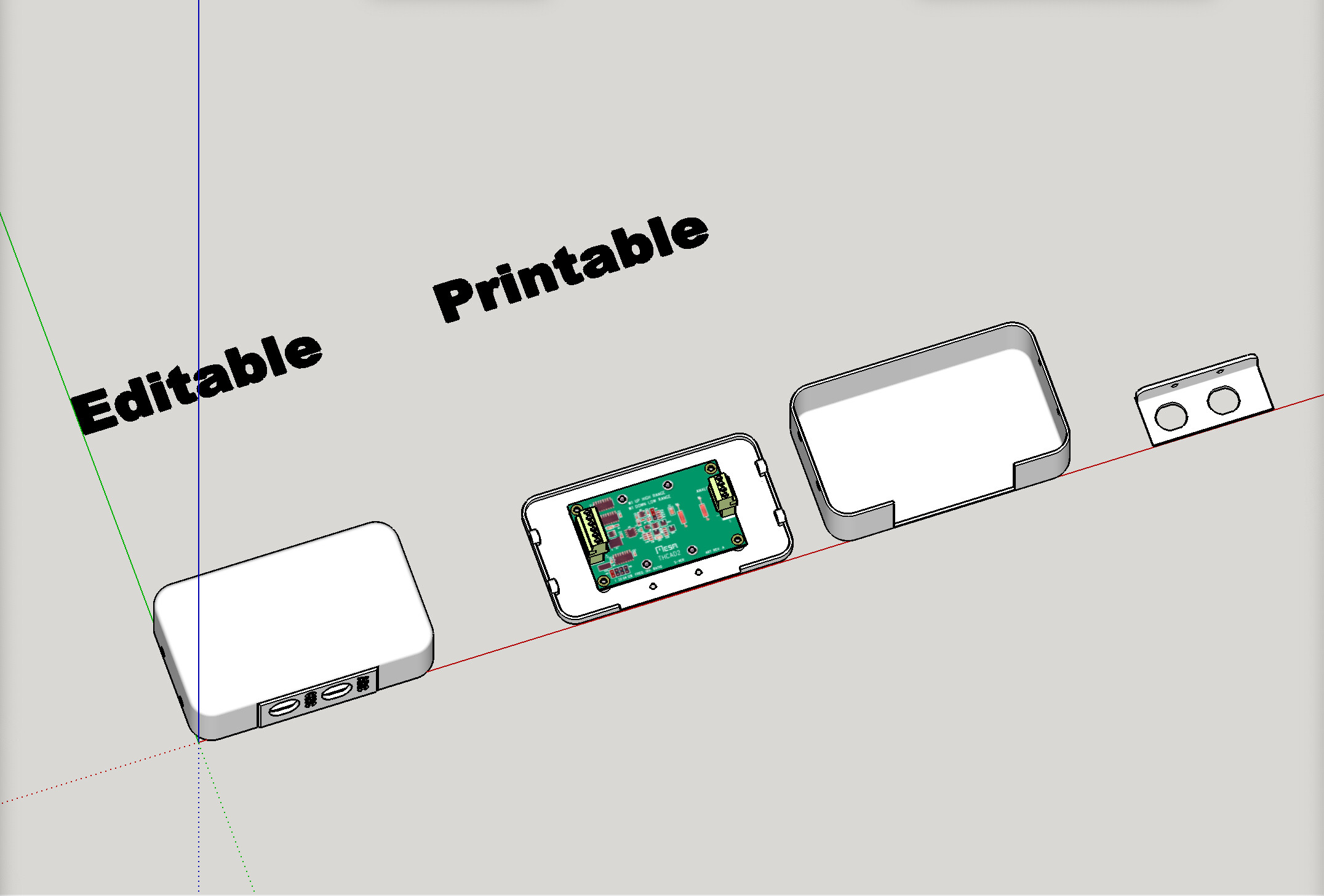
Another micro update on both the connector panel on the control box and a new printed mini-box to hold the THCAD2 at the location of the plasma machine.
Lots of soldering still progressing, to get all the aviation style connectors installed. I’m close to being halfway done there. After all the males are done, still have all the females to wire up and solder.
I also designed and printed a new mini-box to hold the THCAD2 at the location of the plasma machine. I’m not sure how most folks would do this (externally like this versus inside the plasma machine), but this is how it occurred to me to do it. If this is a bad idea, someone let me know, please!
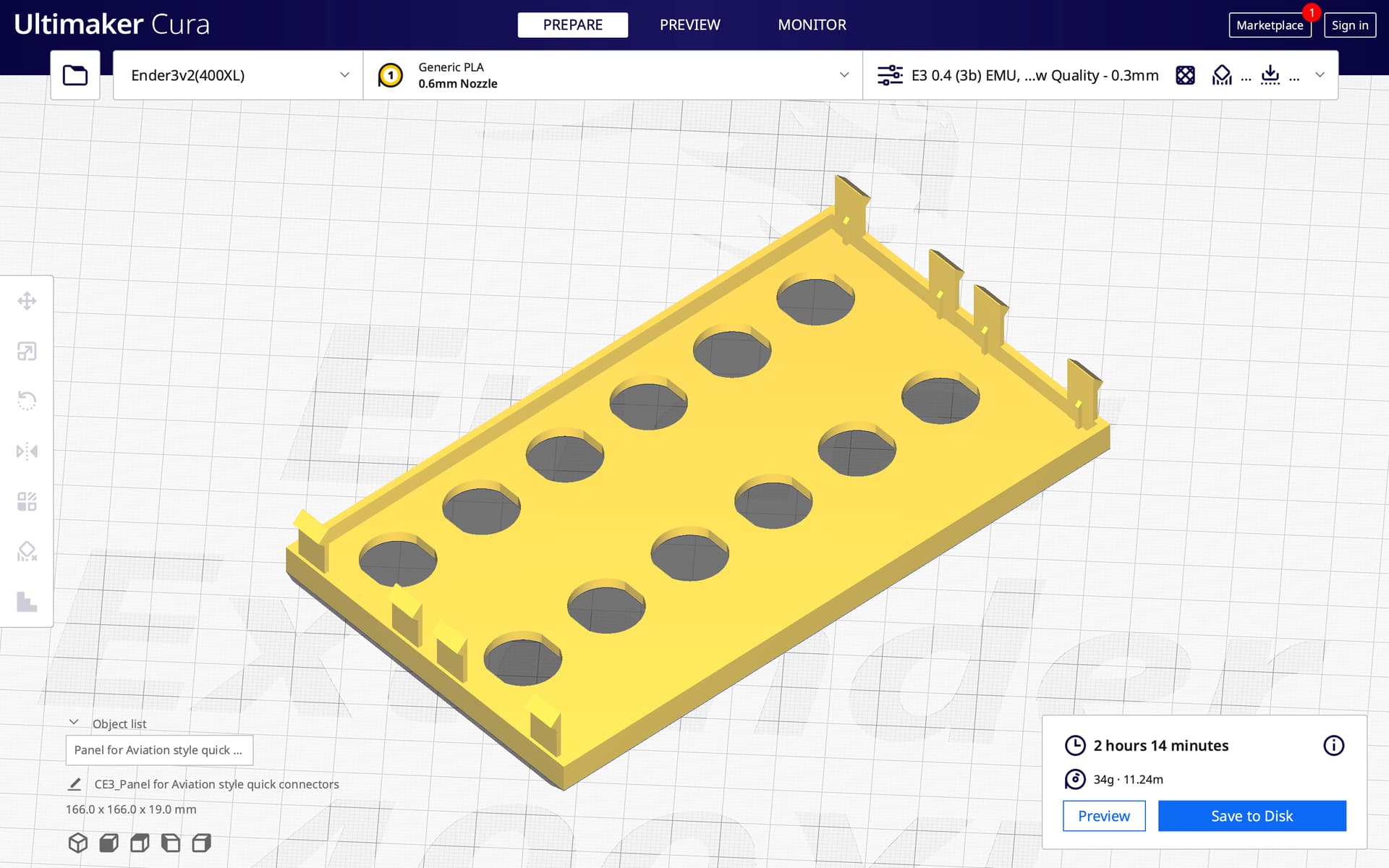
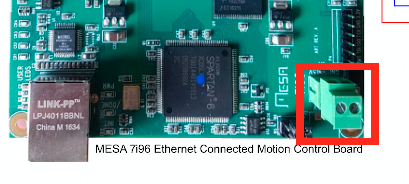
Hey, I could not get the MESA 7i96S to accept power in the 5V & G slots indicated in your wiring plan, and instead had to use the slots in the corner that I saw used in quite a few videos.
Here’s a screen shot of where your wiring plan indicated to bring the 5V power:
Cool. Thank you for the clarification and all the amazing help!
I’ve got quite a bit more soldering to do on getting my aviation style quick connects done and my wiring finished. I’ve been trying to get a head start on the Linux install along the way. I’m learning a lot. There’s quite the load of learning curve here!
I dread soldering those aviation connectors, my soldering skills are crap.
That learning curve is particularly brutal. I made the guide to help get people up and running asap without having to suffer information overload but it’s all different now that qtplasmac has replaced plasmac. The official qtplasmac user guide should get you going though.
Ive been tinkering in Linux and various programming languages for over 20 years, linuxcnc’s HAL has been one of the more obscure to get my head around. But once it clicks it’s pretty simple. I had to stop thinking in terms of scripting/programming and think of it more like wiring up electronic components virtually.
I had seen both names and I had mistakenly thought they were two ways of referring to the same thing. I wonder about the differences, although I assume the newer is better than the older. I guess the newer is the one with that black and yellow skin for the interface?