I usually have a theory about what is going on with a given problem (which is often wrong), but I don’t even have a theory at this point. If it was my problem, my next step would be to plug in some Dupont wires in place of your current wiring and endstop switches, and manually short the wires and run an M119. You need to be absolutely sure you are using the signal and ground pins and not using the VCC/3.3V pin when plugging in to end stops connections.
I might also check the voltage of the signal pin. It should be pulled up to 3.3V. If it is more like 1.5V, then it is floating and it should not be.
I assume you are using just bare switches, not the switches that come on little circuit boards.
I am using the two pins furthest from the stepper motor drivers like it shows in the SKR Pro setup guide. And I am using bare switches, no PCBs on them.
I just tried again using Duponts and manually shorted it, same thing. It will show triggered until I short it, then it shows open but will not return to triggered when the wires are separated.
I checked the signal pin voltages, and they all are reading 2.02V.
I’m just a hobbyist when it comes to electronics, but to me, the 2.02V reading is wrong, indicating the pin is floating rather than pulled high like it should be. At this point, I would be looking at exchanging/returning the board. If you are an electronics hobbyist also, you could do one further test. You could run a 10K resistor between the signal pin and the ‘+’ pin, and then rerun your test.
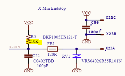
I could not find a schematic for the Skr Pro, but the schematic for the Rambo board clearly shows an external 10K resistor pulling the pin high:
Plus, microcontrollers I’ve used typically have a way to enable an internal pullup resistor.
I concur with Robert, sounds like the internal pullup resistor is either not enabled, or has failed.
There should be a section in your configuration.h that looks like this:
// Enable pullup for all endstops to prevent a floating state
#define ENDSTOPPULLUPS
#if DISABLED(ENDSTOPPULLUPS)
  // Disable ENDSTOPPULLUPS to set pullups individually
  //#define ENDSTOPPULLUP_XMAX
  //#define ENDSTOPPULLUP_YMAX
  //#define ENDSTOPPULLUP_ZMAX
  //#define ENDSTOPPULLUP_XMIN
  //#define ENDSTOPPULLUP_YMIN
  //#define ENDSTOPPULLUP_ZMIN
  //#define ENDSTOPPULLUP_ZMIN_PROBE
#endif
And it should look like that.
If the #define ENDSTOPPULLUPS is commented out, then they won’t be enabled.
If it is defined, Marlin should still not leave those pins floating, the next section should define pullDOWN resistors instead to prevent that.
I’ve had the pullup resistor on one board fail. They’re really low power devices, so it can happen.
The actual value of the pullup resistor is noncritical. I used some 4.7k resistors from a junk box.
Change your endstop plug to a 3 wire type, and plug in a resistor from the (+) pin to the (S) pin. The (S) pin and the (-) pin go to the endstop as usual. There. You have just inserted your own pullup resistor. If the pullup resistor IS working, but it’s just noise… No problem. Worst case is that you have 2 4.7l resistors in parallel, so it’s effectively a 2.35k. The board will EASILY tolerate 470 ohms, (I used one of those on a RAMPS board by accident, misread the colour code. It worked for years before I retired the RAMPS board – which is now in my ZenXY table.)
Anyway, adding in your own pullup resistor is a simple matter, so long as you have something in a suitable range.I suggest between 4.7k and 10k.
I just finished wiring my LR3 and am seeing the similar weirdness that the OP (@chrywo ) is seeing. I am 100% confident in my soldering and wiring. I, too, see the appropriate board SMT LEDs turn on/off when I manually trigger individual switches. I am testing via the TFT touchscreen terminal on the SKR Pro with 2209s.
I’ve done the same debugging steps of removing all of the endstop connectors on the board and then reconnecting them. Once I’m confident in the connections I hot-glued them in position. The board is mounted in the case.
My X endpoint appeared to be working via the M119 command. I homed it a couple of times with success and then it failed and started grinding into the sideplate.
Another oddity, Y2min. If I close the non-rail Y2min endpoint switch, push the reset button and reboot, and execute M119, Y2min registers as TRIGGERED. I release the switch and retest M119, it register open. If I close the Y2min switch again and retest M119, it shows open!? This behavior is repeatable. Booting with the switch closed shows TRIGGERED, but will never show TRIGGERED again.
I am using FW version 513DL from the V1Engineering release on github.
Not sure where to go next. I realize I can use the machine without endstops but this problem is troubling. I’ve spent my career designing/building/testing/producing scientific instrumentation. This build is definitely in my wheelhouse. Something seems very inconsistent in the behavior.
I’ve been following this forum for several years, and the behavior outlined by chrywo is new to me. While it is theoretically possible that this is a firmware issue, since the 513 version of the firmware has been out for nine months and used by hundreds (thousands?) of people, it is highly unlikely the issue is firmware. My best guess is that the pins are the board are bad (not responding to a pullup setting) either due to a manufacturer error, or there was a wiring issue at some point that damaged the pins.
I suggest your first step be verifying this is the identical problem. Carefully check the voltage of each of the signal pins with the board booted. It should be 3.3V. It was around 2.0V for chrywo. Verify (M119) with Dupont wires and direct wire connections if the problem still occurs. This second test takes all of your wiring and switches out of the equation.
If the following two test follow chrywo’s results, a third test would be to wire a pullup resistor between VCC and the signal pin and retest. If the problem is just a pullup resistor issue, adding an external pullup resistor should fix the issue.
There is a fourth thing that can be tried. It is possible in the firmware to reassign endstops to alternate pins. This is something I’ve seen done once for the Rambo board with a bad pin, but I’ve not seen it done on an SKR Pro, but it should work.
Thank you @robertbu. I apologize for my tone. I truly appreciate your thoughtful considerations. The support via this forum was one of the major reasons I decided to build the LR3.
Now to the debug business… i pulled all of my endstop plugs and checked the voltage with a DVM, 1.9999 to 2.03 Vdc on all of the endstop pins at the board! Eureka. It sure sounds like the pullups aren’t there. Apparently something has changed with the SKR Pro assembly process (forgotten parts, bad solder/assembly, cheap parts, etc.) since chrywo had the same issue. Coincidence is unlikely when doing large runs of PCBs.
While I was assembling the other day, I felt using a 2-pin connector in a 3-pin receptacle made for intermittent connections. Luckily I just received at set of crimp pins and housings to make cables so adding a pullup and switching to a 3-pin housing should help.
There’s a 4.7K pullup resistor and a 1K current limiting resistor to the LED. I measured 1.7V across the LED which is fairly typical for a red LED. Looking at the voltage divider of the 4.7k/1.0K resistor, the voltage for pin 3 (signal pin) calculates to 1.98 V which is pretty much what we have measured with the DVM.
So… the question is what changed? Why does this work for some and not others? Looking at the CPUs input/output characteristics, the minimum voltage for a signal to be considered high, Vih, ranges between 1.7 (theoretical) and 2.3 (production unit testing) volts. hmmm, right where we’re sitting. No wonder we’re seeing odd behavior.
I’m thinking that the on-board pullups are there to keep the pin from floating open but an external pullup (about 1.8k to 1.5K) is needed for real world operation.
I wound up getting another SKR Pro and the endstops on the new board work correctly. I guess the first one was just a defective unit, or I messed up the board my first time wiring it.
I ended up putting 1.5K pullups on the connectors and it appears to be working. I now see 2.5V at this input when the switch is open. Hopefully a crown print tomorrow.
That post with the LED’s reminds me, when i was having trouble with mine first time around (i didnt do anything to those two pins on the driver) the red LED by the driver was always on.
I still dont get why clipping/bending the pins matters, its supposed to be for diagnostics or something, and there are jumper pins there - so a jumper should be enabling them.
Other thing i did was look at one of the pictures on the v1 docs i think it was and make my jumpers all match that. I dont know if Ryan does that with the ones he sends out, I only got rambo from v1 not my skr 1.2
Summary: learn from me and make sure you clip or bend those pins to save a headache :>
Initially bent my driver diagnostic pin, but didn’t like that they were potentially touching the cap under the driver (TMC2209 on Skr Pro 1.2 from V1E shop). Ended up clipping my pins. Can always solder suck and replace if/when the pin is needed in the future.
If the issue is correctly identified, an alternate fix might be to unsolder or cut the trace to the LEDs. Based on the circuit you posted, that should cut one leg of the voltage divider and therefore provide full 3.3V to the pin. Still not sure why the problem is happening given all the successful boards. Maybe the internal pullup resistors are not functioning, and that provides enough voltage drop to cause the problem.
@robertbu I agree that this relatively sudden change in behavior is odd. The observed 2 volt is pretty much what the voltage calculates to be according to the schematic. WIth the pullup value that I used, 1.5K, the signal is now sitting at 2.5V which is definitely a logic high for the controller. I will report back if I see the problem again. I don’t really feel like modifying the board.
The pull up solution is working like a champ. I haven’t seen a single failure since then. I have been able to move forward on the build. I’ve cut three 55 inch truss pieces on my 48 inch table by using locator pins, nice plywood yz plates, and 0.25inch aluminum xz plates without issue. I’m glad I installed the endstops and got them working.