Would swapping any troublesome boards to Normally Open help? It mentions sustained voltages. On the SKR that is a very easy fix to flash a new firmware.
The Pro is set to end production next month. I do have a feeling all the other boards are set up similar, though.
When Open drain with external pull up 5V is used
• Hi-Z behaves High output, external pull up will define the output voltage (5V).
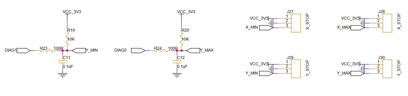
I don’t have issues with endstops not triggering on mks boards that also have a STM32 mcu. The endstop io pins are set to 5V. I don’t have a skr board to experiment with, but in looking at the schematics for both boards, it appears that bypassing the led by connecting to ground through a 0.1uf cap would raise the io pin to 5V.
I’m having the same endstop error. I’m a laymen when it comes to basically this entire discussion. I’ve successfully done the crown test, but am unable to home due to non functional end stops. I’m hoping I just have the ground and signal wires flipped and that will solve the problem. If it’s not the solution, can someone post a more laymen’s guide to solving this problem with pictures.
Ground and signal wires are the same for endstops. Can you make your own post and post pictures of your electronics and endstops? It is probably an easy fix.
I think I may be having the same problem. Z1 Max works. Z2, Y1 and Y2 are always reported as open by M119 regardless of the switch position. Can I provide any additional info? I may have a have some resistors of an appropriate value. I’ll have to look.
What board, what firmware, where did you get it, what endstops, and can you show us a picture of how you have them plugged in on both ends, the board and the endstops.
My bad. I mis-read the line “All the pre-compiled firmware has this disabled so you will need to bend the pins out of the way.” to mean as it disabled in firmware, you will not need to bend… Read the words on the page! Z is now working. The reason that my Z1 worked correctly is there was no driver in the 6th position so that “pin was bent”.
Sorry, I just saw your post/question. Based on that schematic, the endstops should work better. Nothing is running in parallel, e…g, LED, so when the endstop switch is open the voltage at DIAGx is the full VCC and when closed the voltage should be GND.
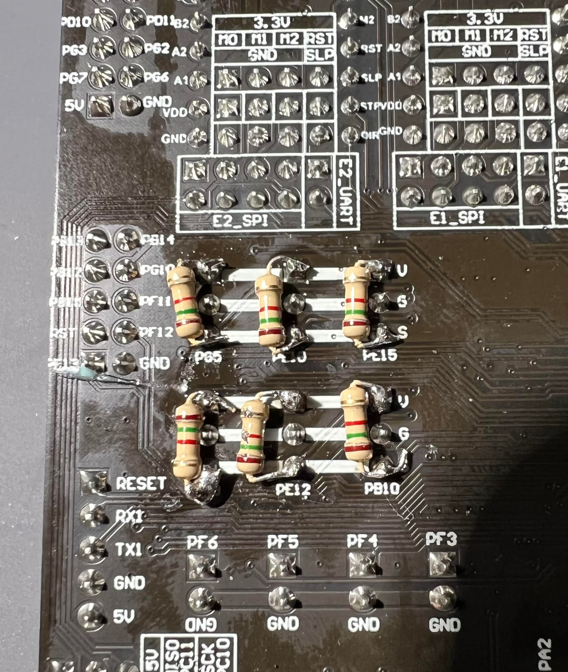
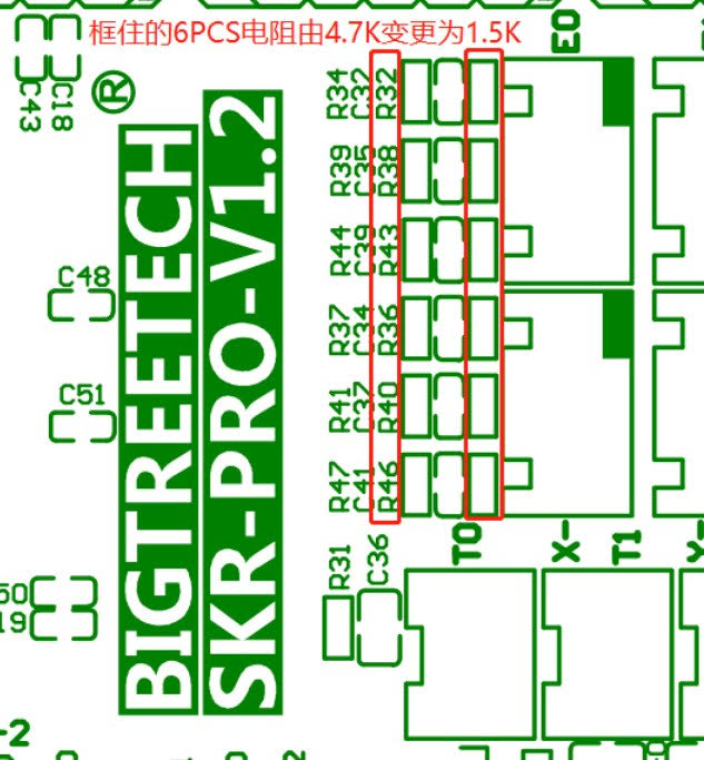
I noticed an issue with homing but I never really used the home feature I guess. Since I have my SKR Pro removed from my Lowrider while I test the JackPot that I just received I decided to add the 1.5K resistors while it’s on the bench. I hope this is correct including a picture. I don’t think I’d miss the homing feature anyway, but might as well fix it while it’s out of the router.
To be honest It’s been awhile and I have just now been able to get back to the Lowrider but I usually set home in my Cut files to the center of the workspace, which always changes. I think I noticed back at the beginning of the build that the Home switches were not working properly and after confirming everything was plugged in properly. Now that I have made the changes with the 1.5K resistors I will retest this afternoon and give and update. Maybe I will start taking advantage of the homing as well.
If you use estlcam and Ryan’s start G code everything works great. I home the machine first thing. then I move it to where I want x0y0 to be for the job. Then once I start the job it will probe the top of the work piece. Really a nice setup and holds everything square and level. That’s if you took the time to do the X gantry leveling and the squaring the machine.
Yes I will try that. BTW, just verified that all axis are homing now with the added 1.k resistors with the SKR Pro! This is why I built the Lowrider 3 and parts from V1 Engineering because of this forum!
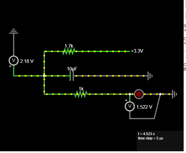
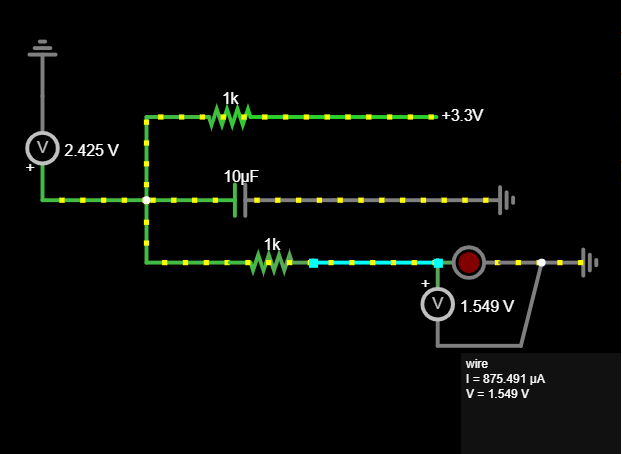
So this new setup gets us from 1.7 to 2.2V but don’t we want to be above 2.3? So a 1K resistor would have been a better solution to get us to nearly 2.4V??
I was thinking it had something to do with the LED voltage, but my crude Web test circuit claims not much voltage difference (I haven’t done circuit analysis in 20 years…don’t judge me)