Sorry I meant actually plug the x steppers into the Z wires and Z steppers into the X wires. Making them go the other way doesn’t narrow it down. So to make it move you will tell it to move 500 in the Z direction but it will actually drive the X.
1 Like
Plug in the steppers as a single plug, or each one into one of the ports on the board?
Without serious mods to the firmware, this won’t drive them the same and if it does, then you’ve duplicated series wiring.
I don’t see how anything in the controller or driver could cause this in series wired motors. I am still skeptical of the belts. Unless something is skipping steps.
Can you count the number of teeth (and generally inspect them) on 200mm of each belt?
Sorry, I haven’t listened to any videos. I have been reading this topic in bed, and I don’t want to wake anyone up.
There is another thing I’m seeing that is perhaps interesting. First a summary of the measurements:
Video 1, move 600 mm from hard stops
- right side measurement 21 1/8 inch or 536.6 mm
- left side measurement 20.5 inch or 520.7 mm
Video 2, move 500 mm from hard stops
- right side measurement 17 3/16 inch or 436.6 mm
- left side measurement 16.75 inch or 425.45 mm
The measurement distance is not equal to the command amount because the measurement point is not made between the points that contact at the hard stop. This is perfectly fine, it just has to be included in the model for what’s happening.
Observations:
- Right side measurement is exactly 100 mm shorter between video 1 and video 2 when the movement is supposed to be 100 mm shorter, which suggests the right side is moving the exact right amount and the left side is the problem
- Left side measurement is 95.25 mm shorter when the movement is supposed to be 100 mm shorter, which would suggest a 4.75 mm error over 100 mm if it were perfectly repeatable. This is larger than the 2.25 percent error estimated before. The magnitude of the error can be helpful to hint at the source but I’m not seeing a smoking gun yet.
- The measurement references being different from the hard stops is not a problem but if the difference is not the same on left and right it can introduce a phantom error or skew the measurement of the actual movement error.
Each side has some amount of overlap between the measurement points when pressed against the hard stops, i.e. at the hard stops the distance measured would be about negative 63.4 mm on the right side. On the left side I’m not sure but one would hope it is about the same. This should be easy to check. Hold against the stops as before and then move just 70 mm. See if the distance from the carriage to the belt block (like you’re currently measuring) is the same on left and right. I would expect it to be about 6.6 mm on the right, and on the left maybe it’s a different amount?
Another thing that can give more information is to install a pen and move the tool to the left edge (which I am suspecting to be the bad one), and draw a ruler just along the bad axis. Longer is better but 250 mm should be enough and fits on one sheet of paper. This will tell you if you have backlash and if the movement error is uniform or if it is lumpy. Backlash has been eliminated as the sole problem but if it occurs together with another problem then it can make things harder to pin down. Lumpy movement error could mean… I’m not sure what but the spacing might point to something.
You can also start physically switching motors around but that’s more work so if it were me I would start with something easier.
1 Like
Thanks for the feedback guys. I am at the in-laws for a few days but when I get back here is my plan:
-
Move out 300 mm, 600 mm and 900 mm and measure at each from hard stop to vertical tube with my metric tape measure to see exactly how far it is moving and if it is proportional and matching the commanded distance. My guess matches Jamie and the right will be correct and left will be proportionally short.
-
As Ryan suggested, plug the y steppers into the wire harness for the Z. Test.
-
Is it possible to use parts of my series wiring harness to run each stepper off of a different driver (if I only use 1 of the plugs on a series harness will still work, or does it need the loop of both motors)? I was thinking hooking 1 up to the y and another to the x and run a G0 X300 Y300 command then measure. This would remove the wiring and drivers from the list of possible problems.
If the 3 above mean the left side is proportionally short I will disassemble and check the gears on both to make sure they are the same and switch steppers from side to side.
1 Like
With current wiring (ran twice, the difference was with 1mm on each):
Y100
Right Side: 100mm
Left Side: 98mm (2mm over 100mm)
Y200
R: 200mm
L: 196mm (2mm over 100)
Y500
R: 500mm
L: 484mm (3.2mm over 100)
Y1000
R: 1000mm
L: 944mm (3.6mm over 100)
I got an individual wiring kit from Ryan/V1. I wired the right stepper to the X driver and the Left Stepper to the Y. I repeated the below moves 5 times, numbers were the same each time.
G0 Y200 X200
Right Side: 197mm
Left Side: 195mm (1mm per 100)
G0 Y500 X500
Right Side: 497mm
Left Side: 487mm (2mm per 100)
I think I am going to flash the board to current firmware to eliminate that since the difference changed with the thicker, shorter wiring, and it would be nice to have the Z speed limited better from the new firmware so I don’t have to set that each time I connect to the board with cnc.js.
Updated the firmware. Put the wires back to series and got the same results…off by 2mm per 100 over 400mm and over 500mm (separate tests).
Tomorrow I am taking it apart and switch the y stepper that is giving me problems and x stepper (which is right on).
1 Like
I’m not experienced with stepper motors but am experienced with troubleshooting things in general. And being new here, I don’t want to present myself as an expert.
Since the left is lagging behind what it is supposed to be, my first suspicion is slippage of the pulley. But assuming they are tight, I would put marks on the pulleys when homed and run the gcode to move them. If they end up in different positions after the move, then I would remove the belts, remove the pulleys and tape a flag to each shaft and turn the steppers so the flags are in the same position. Then I’d run the gcode to make the steppers spin. If they don’t end up in the same position as each other, then it’s electronics issue (maybe bad stepper) but if they do end up in same position, then it’s mechanical.
3 Likes
I think madgrizzle has it. Your error is not doubling with double distance so it is not a firmware issue it is hardware related in some form and loose pulley is far and away the #1 issue on all builds.
1 Like
I feel like a chump. It was a loose pulley. Ryan was right!
2 Likes
Well besides getting your build dirty finding a loose pulley is the next major milestone in any good person on this crew!
1 Like
Never seen a solution tag in this forum, but I think that tag shouldn’t be on my post but on @bcdcmcnamara’s who suggested it first…
3 Likes
Somehow it’s always a loose pulley. Lol.
Sneaky buggers…I think we need a loose pulley shirt but the only things that come to mind are not family friendly.
2 Likes
Dear Abby,
Recently my sister’s boyfriend has –
Let me stop you right there. You have a loose pulley. Check for a loose pulley.
6 Likes
<ShowAge>
Dr. Ruth,
Lately, I’ve had this issue with my…
Iz loose pully! Iz alvays de loose pully! Tighten zat sucker up, und haf FUN!
</ShowAge>
You young 'uns: Dr. Ruth was the Jewish grandma we all wanted, but no one deserved… Google her, and see if you can find some footage of hers. At home, as her better stuff is NSFW (usually audio-wise, I don’t recall many visual aids).
I too have suffered from loose pulley. But with rehabilitation and the right medication I have recovered.
2 Likes
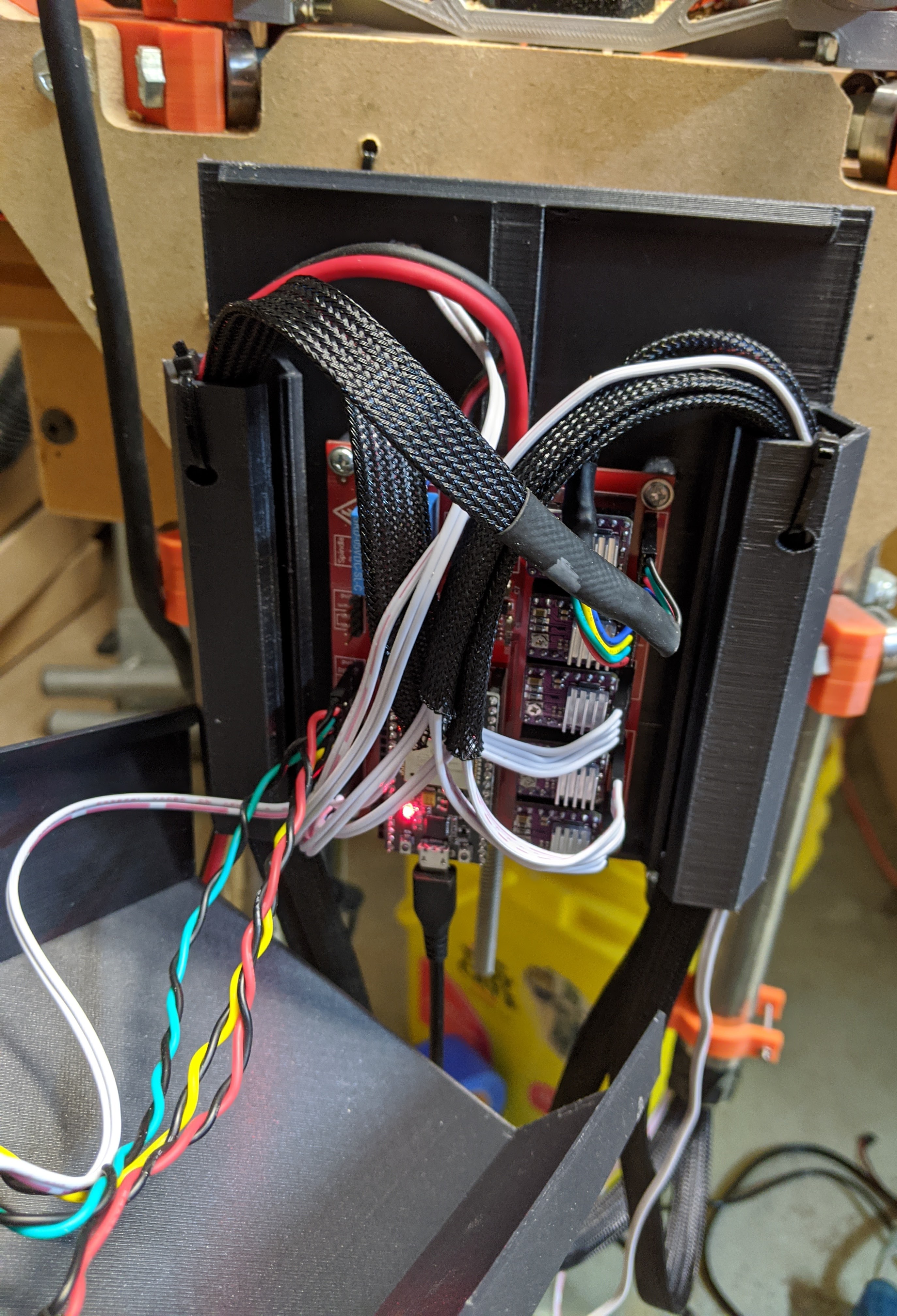
It has been awhile, but I am getting back to this. I wanted to get this running on GRBL (and with endstops) as Marlin felt clunky for CNC work. GRBL also looks to be a better fit for the laser I want on it. So I got a MPCNC ESP32_GRBL board to run it. Board and features looks awesome, but I have not had it completely running yet as a bad driver burned out on it and I need to order another…grr. Anyways, I am going to stick with this board and I needed a case for it. I played with using the Mini-Rambo case from Ryan with new mounting holes for the SLIGHTLY larger board, but the case is just too tight with all five drivers and cables, so I designed a new one (tickercad special, I really need to learn a grown up cad program…). Printing tonight for a test.
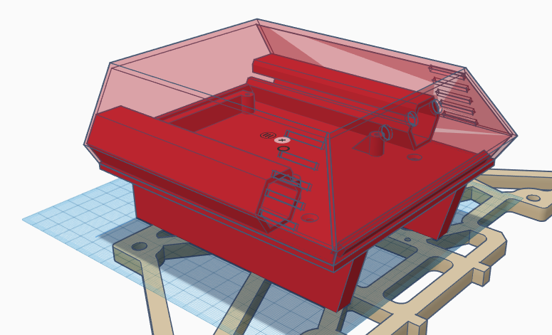
2 Likes
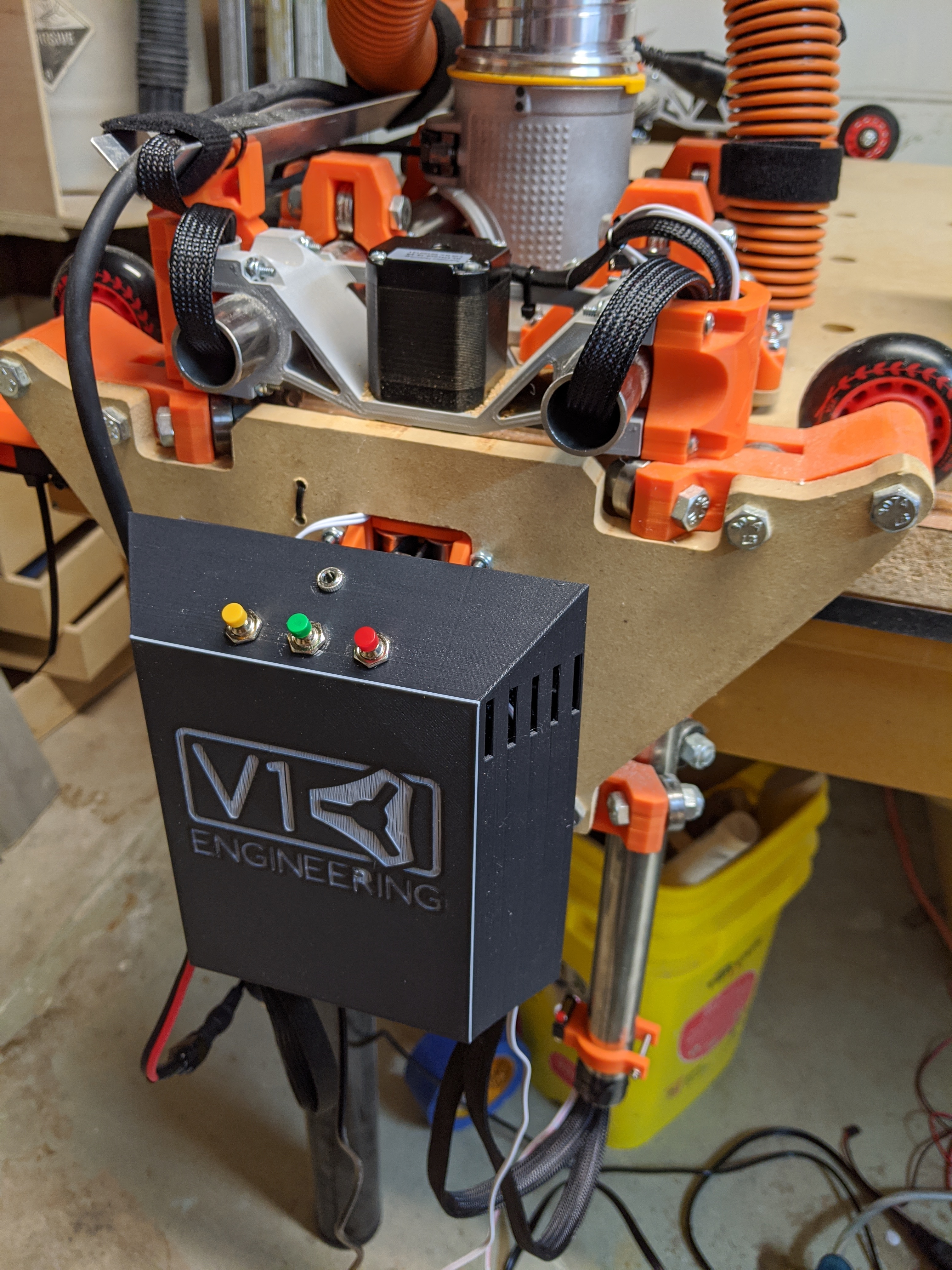
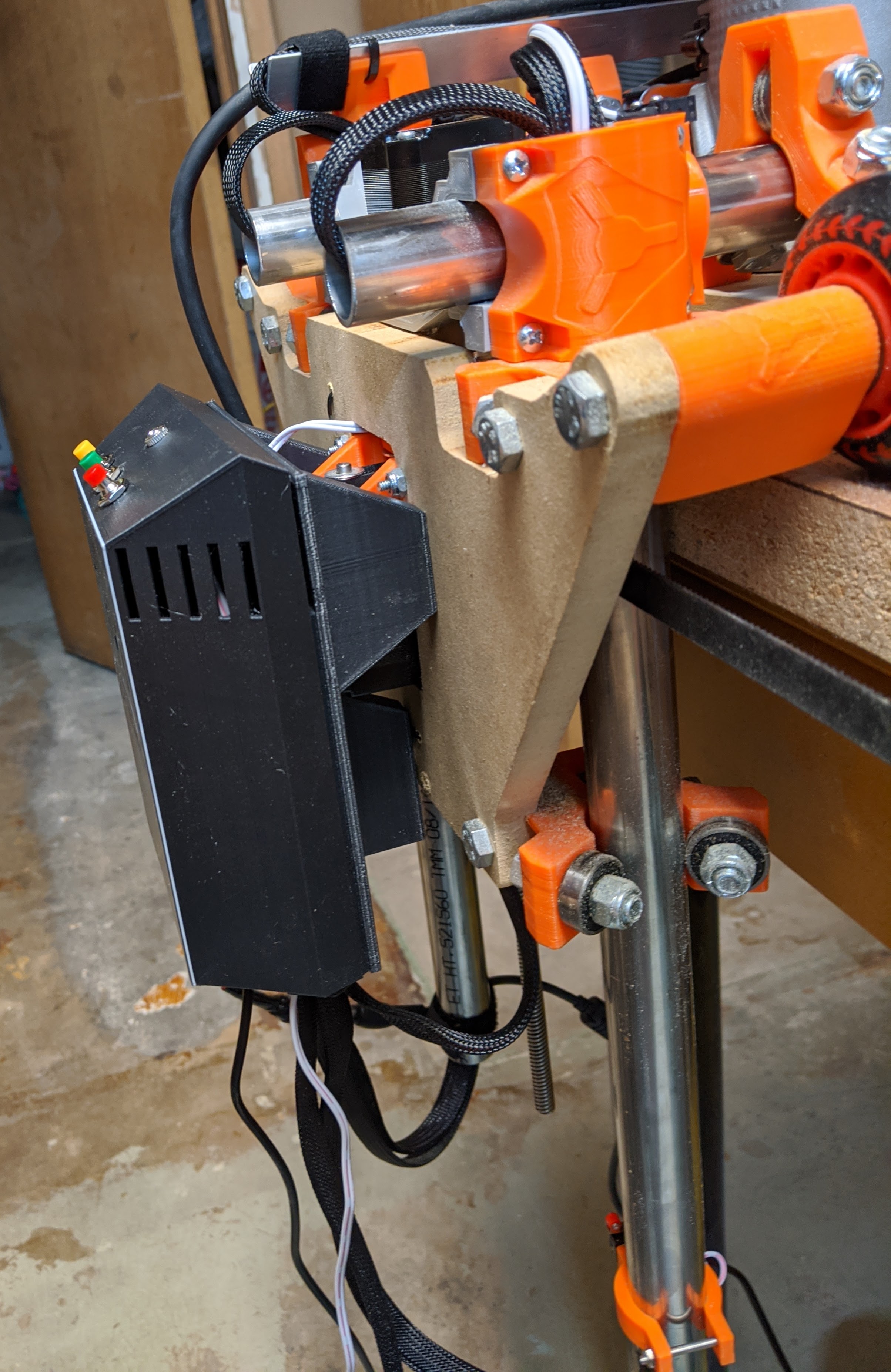
The case turned out great (I think) for a tinkercad special. The buttons on the top are Hold, Start, and Reset for GRBL. Above that is a stereo jack for my touch plate. I think I am going to make the cover a little stiffer with some internal supports and remove the reset button as I don’t see me using it (and I don’t want a button that will complete nuke a job). I love how the case sits on the end of the lowrider.
On my todo list is getting my 7w laser running on it and maybe get the spindle relay setup.
8 Likes
Here are the files for the case if anyone wants them. https://www.thingiverse.com/thing:4531745
4 Likes