I managed to run the z down too far and permanently stretched out one of the z couplers. Ill reseat the lead screw to contact the motor shaft but how stretched is too stretched?
1 Like

Nope, I have a few that are worse than that. Over the years I have really tortured a few, on on the lowrider and one a few on the printers. I just re-seat the screw and keep going.
1 Like
Finally got it temporarily wired it up for some testing. It’s a start!


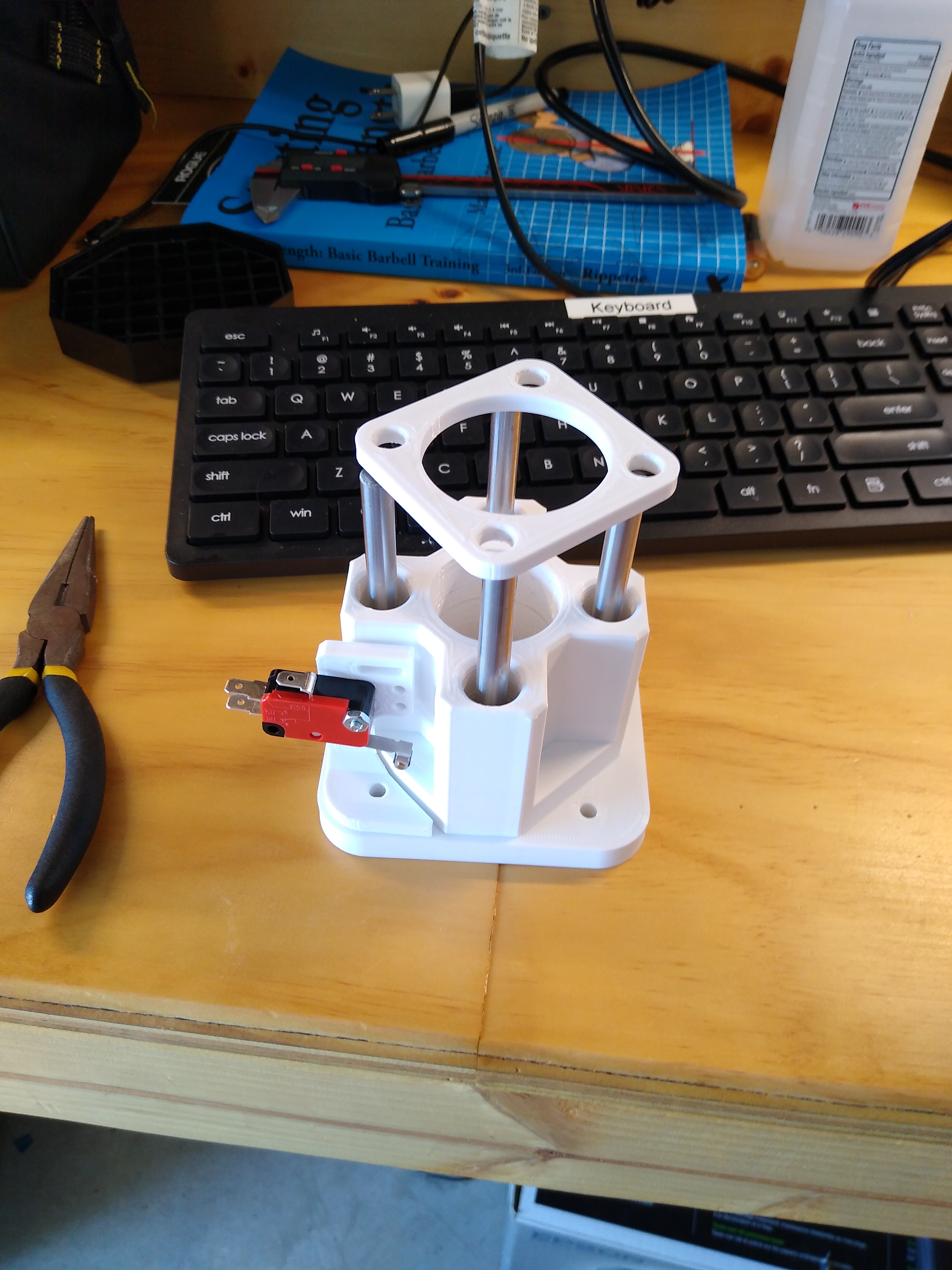
This pen mount from thingiverse is pretty slick but there’s some room for improvement.
[edit]
For anyone following along re linuxcnc, you’ll notice in the pics that the pen cut some corners and rounded them over instead of being sharp. This is partly because the pen was wobbling in the pen mount but mostly because the linuxcnc trajectory planner, a “feature” called path blending. To fix the issue I’ll need to put the G64 gcode at the top of my gcode files.
http://linuxcnc.org/docs/2.6/html/gcode/gcode.html#sec:G64
5 Likes
I stretched my first set of couplers out WAY more than that. I did replace them. Thankfully Ryan sells them cheap. Discovered it’s important to note whether you’re in G20 (inches) for G21 (mm) mode. Bad things happen when you try to jog the Z down 25mm, only to realize - Too Late - that you’ve instructed it to jog down 25 inches.
Thanks for documenting this so thoroughly. This approach is more affordable than I had realized. I’ve noticed that open source CAD/CAM options seem to support LinuxCNC better than other control mechanisms. While I won’t do so soon, I may follow your example at some point in the future.
2 Likes
It can be cheaper still if you find an old computer with a parallel port and use a parallel port breakout board instead of the ethernet break out board and/or use the drivers off of a arduino cnc shield instead of the tb6600’s that I used. @dkj4linux has a write up on that here: Inexpensive LinuxCNC interface for MPCNC
That said I like the mesa card enough that I’ll probably be buying them again for future projects.
Hello. I’ve been reading your post for a while referencing this thread for my project. It’s been a lot of help and I thank you for that. I was wondering how things are holding up, and if you have a complete wiring diagram with all your components included?
3 Likes
Sorry for the late response. My project had been put on hold for a while now. But we just moved into a new shop and I’m getting back into it. Right now I’m trying to figure out how I’m going to implement a down draft system.
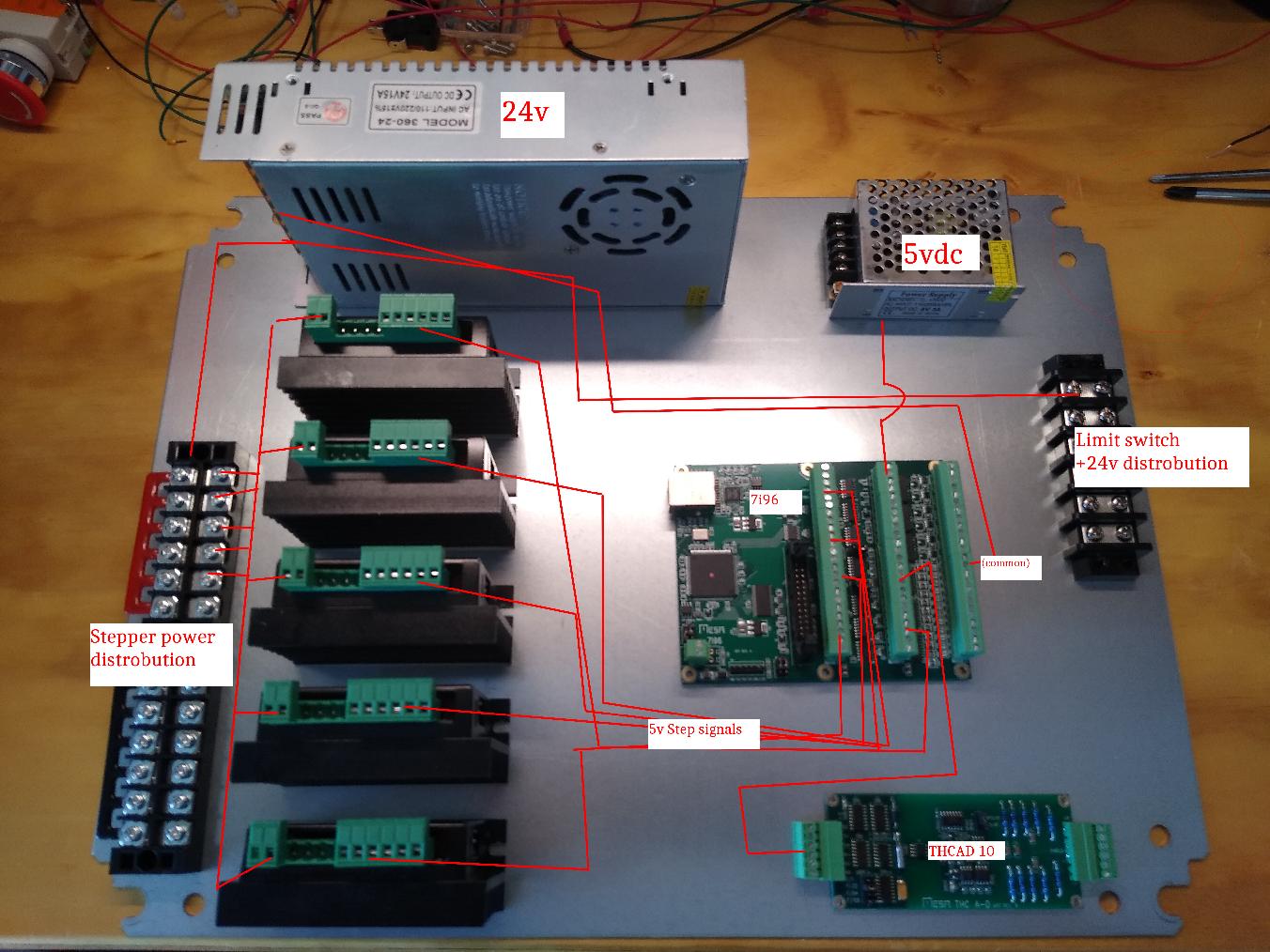
I’ve also picked up a new NEMA steel enclosure I’ll be moving the electronics to. My wiring plan won’t change much from what I’ve shown above. I will be adding 12 vdc for a computer fan and I may use a relay instead of the fuse when wiring up the plasma cutter… We’ll see.
I assume there had been a lot of updates to linuxcnc plasmac so I’ll need to play catch up there too.
New hypertherm should arrive this week!
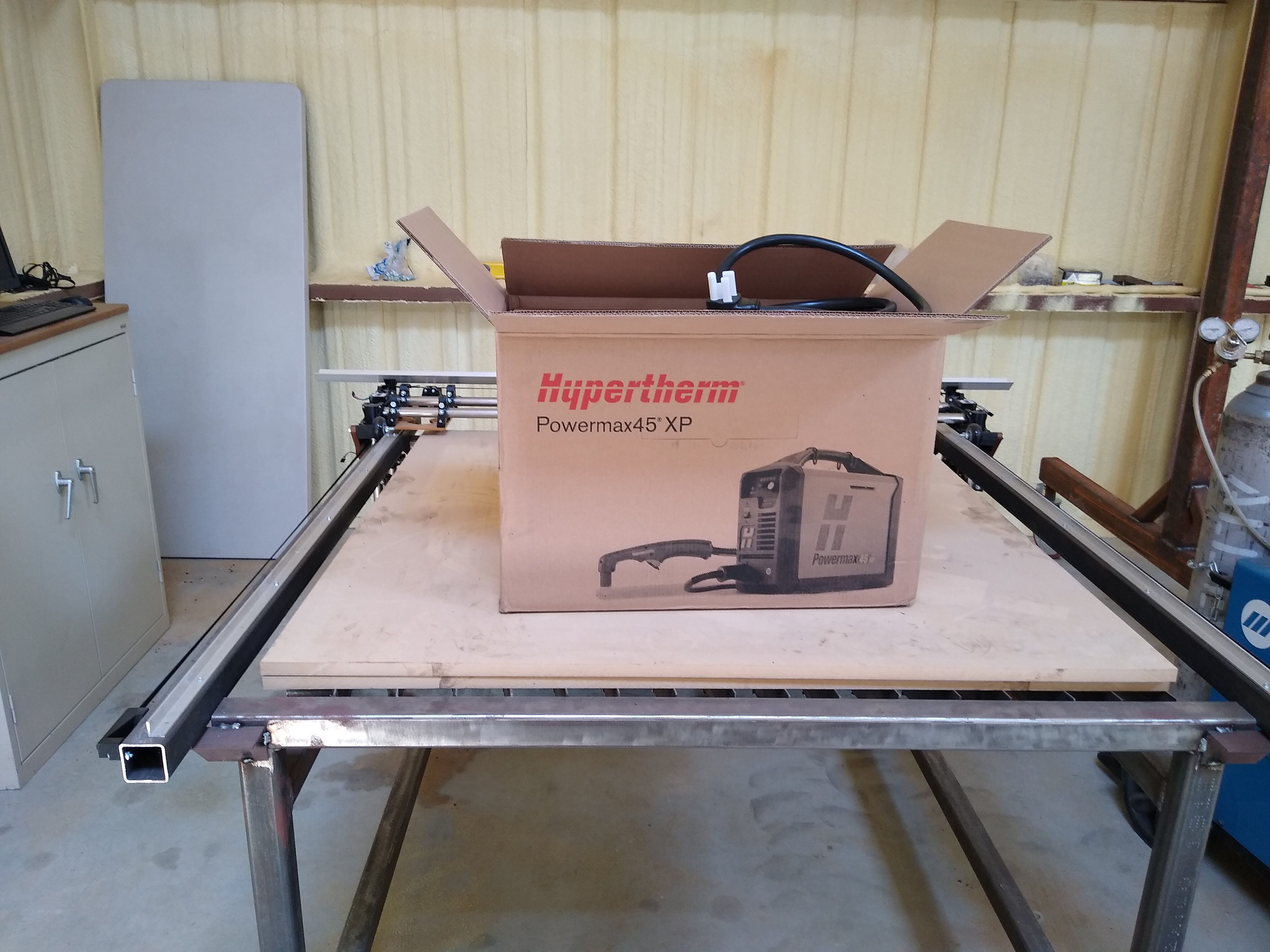
I am very very interested in how this plays out. Did you buy the straight torch as well?
That is going to be hard on the wood spoil board but o so kool. I have wanted to do this for a long time just @forcerouge had so much trouble but maybe it’s time for round ? And to get my garage cleaned and ready
1 Like
Yeah but if I remember correctly I think his emi issues were rooted in the particular plasma machine he was using. People have reported good results with this specific model so hopefully I won’t have as much trouble as @forcerouge did. Knocks on wood
2 Likes
I will watch I don’t really need one not sure what I will use it for but is sure is cool if it does work like thay say maybe I’ll find a good use😀
(Cross posted here: https://forum.linuxcnc.org/plasma-laser/36734-lets-talk-wiring-and-emi?start=20#177702)
I’m trying to be very careful about EMI but I aint no electrical engineer. Anyone have any opinions on this control box layout? This will be mounted vertically with the stepper drivers up top and the motor and signal wires coming up through the bottom of the box (right hand side of the photo)
1 Like
If the control box is metal, and grounded, there won’t be any emi going in or out. It will act like a faraday cage. The fact that it looks anodized or painted makes me think it might have trouble being grounded, so you might want to grind off the area around one of the screw holes so the case and the door can both be at ground, and then ground the whole thing with a screw or to the power supply case (which should be ground, unless the manuf. are jerks).
IIRC, Dui’s biggest takaway from his mammoth grounding project was to put the motor cables in a shielded cable and then ground that shield on one end (the controller end, presumably).
There shouldn’t be any significant EMI inside this case.
2 Likes
What 5VDC power supply is that? Is that from the 24V, or from A/C? I’m just curious because I’m not happy with the DC to DC converter I have in my printer for the raspberry pi.
1 Like
It’s a bonafide steel NEMA enclosure! The mounting plate in the photo is galvanized steel. Both power supplies are 120vac input.
I do plan on grounding the mounting plate to the enclosure’s grounding post. Actually, the first thing I did when I got this thing in the mail was poke around with a multimeter for continuity and discovered that the mounting plate is isolated from the enclosure. I haven’t figured out of that was intentional or simply due to the rubber washers used to mount it to the panel that are for water proofing.
It can be dangerous, especially if you’re running A/C close to it, because that can arc. But you can short stuff that way anyway, so you might as well ground it.
2 Likes
To both ends actually. What I found out worked was to ground the motors casings, once they were grounded it worked like a charm. I’m not sure I even needed to shield the motor wires, but I used the shielding to achieve both, connectin the motor casing to one side and the earth ground of the electronics bo to the other.
@OP If this explanation is not clear just let me know and I’ll make you a quick drawing.
4 Likes