A-Z -Where to find the latest info on setting up the Rambo 1.4 firmware. Wiring for the Rambo 1.4 board for the Z max switch? By looking at the pic of the Rambo 1.4 board on the doc page I can see the X1 X2 Y1 Y2 is the next set the Z box’s. The Rambo board was purchased from Ryan.
Wiring info can be found here. Pay attention to the table of connections on this page. A common mistake I see on the forum is to attempt to use the second Z plug rather than the second extruder plug for the second Z stepper. The two Z plugs share a driver, so using them will leave your Z axis underpowered.
The latest firmware can be found here. The “V1CNC_Rambo_DualLR-2.0.7.2-src.zip” file is the one you are looking for. Note the “LR” in the name. Also if you purchased from Ryan and included dual end stop wiring with the purchase, you likely already have a version of the firmware that will run dual end stops on the Rambo board. If you look at the LCD when the board boots, or if you send an M115 from Repetier-Host, you can see the version number. Dual end stop versions will have a ‘D’ at the end.
On this page https://docs.v1engineering.com/electronics/dual-lr/
It says to wire the switch N/C

Then on the same page it says
So my question: Is the switch wired N/C or N/O I am thinking N/O
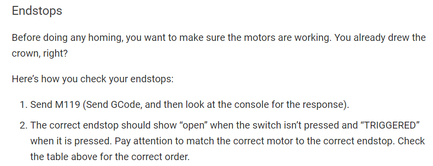
Question 2: In Repeater Host where do you type the M119 command to test the endstop switch. I typed it under the tab Manual Control and press send and it does and shows nothing. Is this right?
N/C is correct
Make sure the Log button is checked. Top left hand corner next to the Kill button.
V1/Ryan selected NC switches so that if there is ever and end stop failure like a broken wire, homing will result in no movement rather than crashing against the end stop blocks. This default can be easily changed in the firmware.