The recipe I followed: Bid farewell to LR2 without getting too emotional Scavenge for usable hardware, electronics and feel good about saving some money for the new build Fire up the 3d printer and MPCNC to generate the desired parts Follow the instructions from Ryan and see the LR3 magically come to life
Next step is to draw the crown and follow it up with some actual cutting.
@Ryan Here are some observations from my own LR3 build. These are not meant to suggest changes in any part of the existing design or documentation since everything on your website is spot on.
I noticed that the available work area has reduced compared to LR2. I understand that it is for a good reason but if someone is willing to live with the constraint of not being able to push their table against a wall, then they may be able to gain almost 100 mm back by just mounting the belt brackets on the side. So, an optional part which can make it backwards compatible w.r.t mounting may be nice. I designed one for my use but if you don’t see any merit, pls feel free to ignore the suggestion.
I found the adjustability of the z endstop a bit limiting. Had to come up with a more adjustable endstop that could be mounted on the XZ plate.
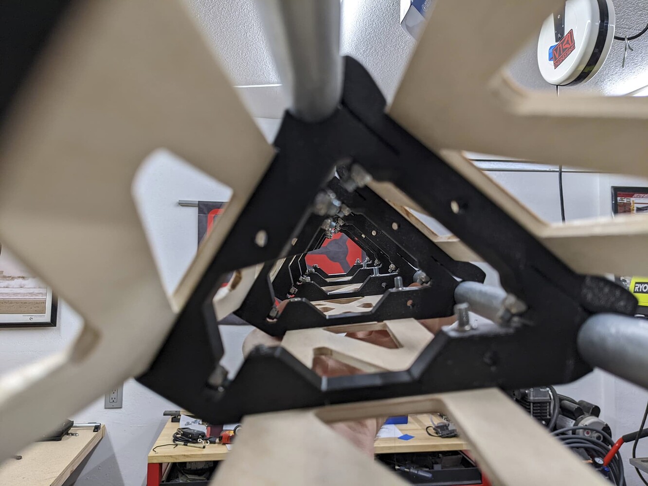
If someone choses to have beefier YZ plates, then one of the zip tie holes on the Z drive gets obscured which may impact the wire organization.
Again, none of the above are a deal breaker as one can always find a way around them. So you may just take them as an FYI.
Great job! I concur with the various observations. Check out my build thread for the 3-D printed end stop/tensioner holders that I came up with that allow me to have the belts suspended away from the side of the table so that I can still have close to the same cut area that I was a accustomed to with the LowRider 2. Also I did indeed use a beefier 3/4” MDF for the YZ plates, and I used a Dremmel tool with a toothy gnawing bit to chisel out an area so that I could still get access to that zip tie port that gets half covered up. I also had to whittle a little area for the Z couplers but it was not hard. MDF is easy to whittle on.
This seems to be how @DougJoseph is doing his, but Im pretty sure that this is only an issue for upgrading from LR2. I will say thay Doug’s work has me wishing that I could have had Superstrut on my table… but it isn’t available here
Weird, i can’t quite get mine entirely level, but it should be easy enough to do in software (M666) and it should allow almost as much motion as the YZ plates and linear rails will allow, maybe 1-2 mm more at most is possible. If you are more limited than that, I’d think something is wrong…
Beefier YZ plates, yeah. 12mm thick ought to be enough, but I’ve already seen several builds using 18mm. I wouldn’t have anticipated that. I’d personally rather go to stiffer material and keep the thickness down. 1/4" steel would be amazing…
I wouldn’t say so. The printed XZ parts are fine. Plenty rigid enough, just they do allow a little bit of room for imperfect alignment. Milled metal plates offer improvement there and of course are also extra rigid, which doesn’t hurt, but the printed parts seem to be about as rigid as plywood or MDF, which is enough not to be a problem. Of course metal is more rigid.
The YZ plates basically have steel reinforcement beams (The linear rails) bolted to them, so they’re going to be plenty rigid in 1/2" plywood no matter what.
Here is the first test… the illustrious crown and the (gantry) head in all its glory… Recommend playing it at 2x if you don’t want to get bored to death
Using an LR2 table, yes. But the overall footprint of the machine has been reduced for the same amount of cutting area if not coming from an LR3.
This is coming up a couple times now. The travel of the printed part is 2mm or so. That is not much but… You can bend the tab on the microswitches like a full 12+ mm. There is absolutely no issues with that. The force of homing will not band them back. I was not going to put any adjustment in the parts because we use M666 to actually adjust them. The only reason I actually made them adjustable was to account for roller and non roller switches.
I guess it seems weird for some to bend the tabs but this is how we used to do it on printers, for a while.
So does the Coupler. Above 13mm you need to make manual adjustments. So instead of going thicker, I highly suggest just using more rigid material. At some point there has to be a limit, right?
It was originally designed for MPCNC but you can use it anywhere as long as you can find a suitable way to attach it - screw or tape or whatever works…
Good observation but no The board is 5 mm thick. I cut an extra set in case I decide to double up for extra strength. However, I just tried doing a dry fit a few min back and I am not sure if there is enough clearance there. So, I guess I will just leave out the extra set.


 The board is 5 mm thick. I cut an extra set in case I decide to double up for extra strength. However, I just tried doing a dry fit a few min back and I am not sure if there is enough clearance there. So, I guess I will just leave out the extra set.