So just for clarity sake, these images are correct, that show the nuts on the same side as the XZ plate?
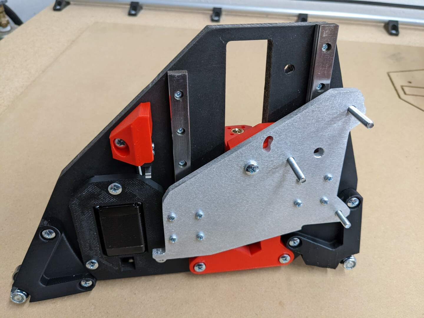
… And show the bolt heads on the same side as the stepper motors?
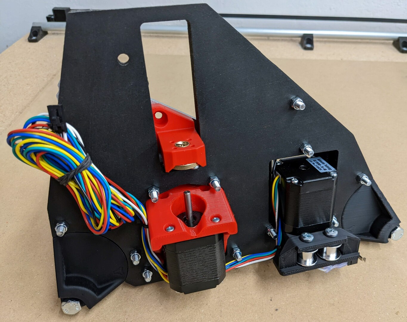
That seems to me like screw heads facing out, rather than in.
So just for clarity sake, these images are correct, that show the nuts on the same side as the XZ plate?
Sorry axle bolts, not the M5’s
I was focusing on the axle bolts. I’m still confused. The wording and the pics don’t seem to match. The side with the stepper motors showing I’m calling outside, and the side with the XZ plate, I’m calling inside. The pics show axle bolt heads facing out (if I am right on what is out), and nuts facing in. Yet if I am not mistaken, that is the opposite of the wording. I’m quite possibly wrong. Just trying to get clarity. 
Just like the picture shows. This statement “Wheels installed, Heads in Nuts out. Snug these four screws.” is referring to the M5 screws. Heads in towards the center, nuts out like all the rest. Would that be a better way to word it?
Ah got it. I guess we were talking past each other.
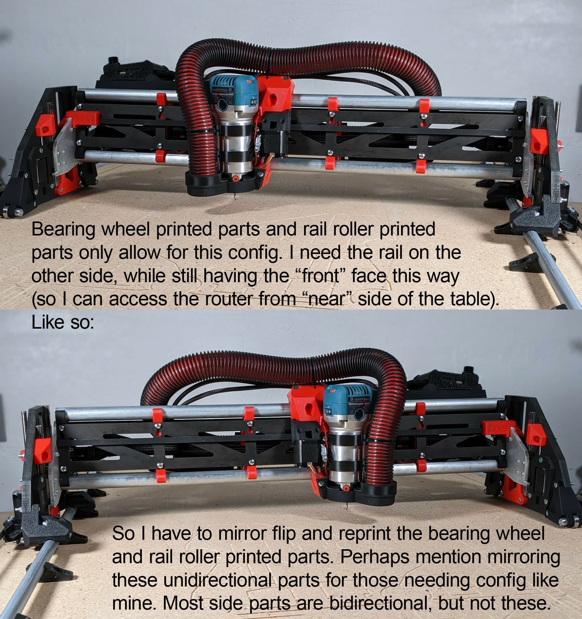
Also, one idea/suggestion: See pic below for gist of it.
I thought I had that listed somewhere near the parts list already. I will double check and add it if necessary.
I had 9 pages of notes, I could have missed it. I’ll check in a bit.
This:
- Side Plates are done!
- Roll them around on your table making motor noises to make sure they work right.
… is hilarious!
From LowRider CNC V3 - V1 Engineering Documentation
…And this too:
- Best practice is to make robot noises while you move it up and down (feel free to tag me in your video when you do #V1LR3).
Culminating in:
- You nervous yet? It is time to fire it up! No need to make your own noises anymore it will do it for you. See I thought of everything.
From just before: LowRider CNC V3 - V1 Engineering Documentation
Ahhhhh lots of coffee and I do weird things. By that, I mean make random noises while I play with prototypes. 
Hey, are the Y belt tensioners designed with some easy way to remove them when not in use? If so, how does that work?
Yes. they’re designed in 2 parts, the top part (with the belt) can be easily removed. 1 5mm screw on each side
Idea / suggestion: the two screws for the XZ plate that have to be inserted before attaching the XZ plate to the YZ plate, and which have “tool access” holes drilled into the YZ plate:
If those “tool access” holes were a little bit bigger, the screws themselves could be inserted (and/or removed) though the holes while the XZ plate is already in place, and it would simplify the build.
It would also simply things if the screws ever have to be replaced for “some” reason.
I had to replace those screws with longer ones, even though they were already in place and my XZ plate was already attached to my YZ plate. (Reason: I’ve been using 25mm M5s for the whole build, as I had a bunch of 25’s, and no 30’s, and I’d gotten away with it all the way until that point.) Full disclosure: I already drilled the holes out larger (used a 1/2" bit) and replaced the screws without disassembling things. If there is an engineering reason why that ought not happen, it’s too late for me, as I’m not redoing it.
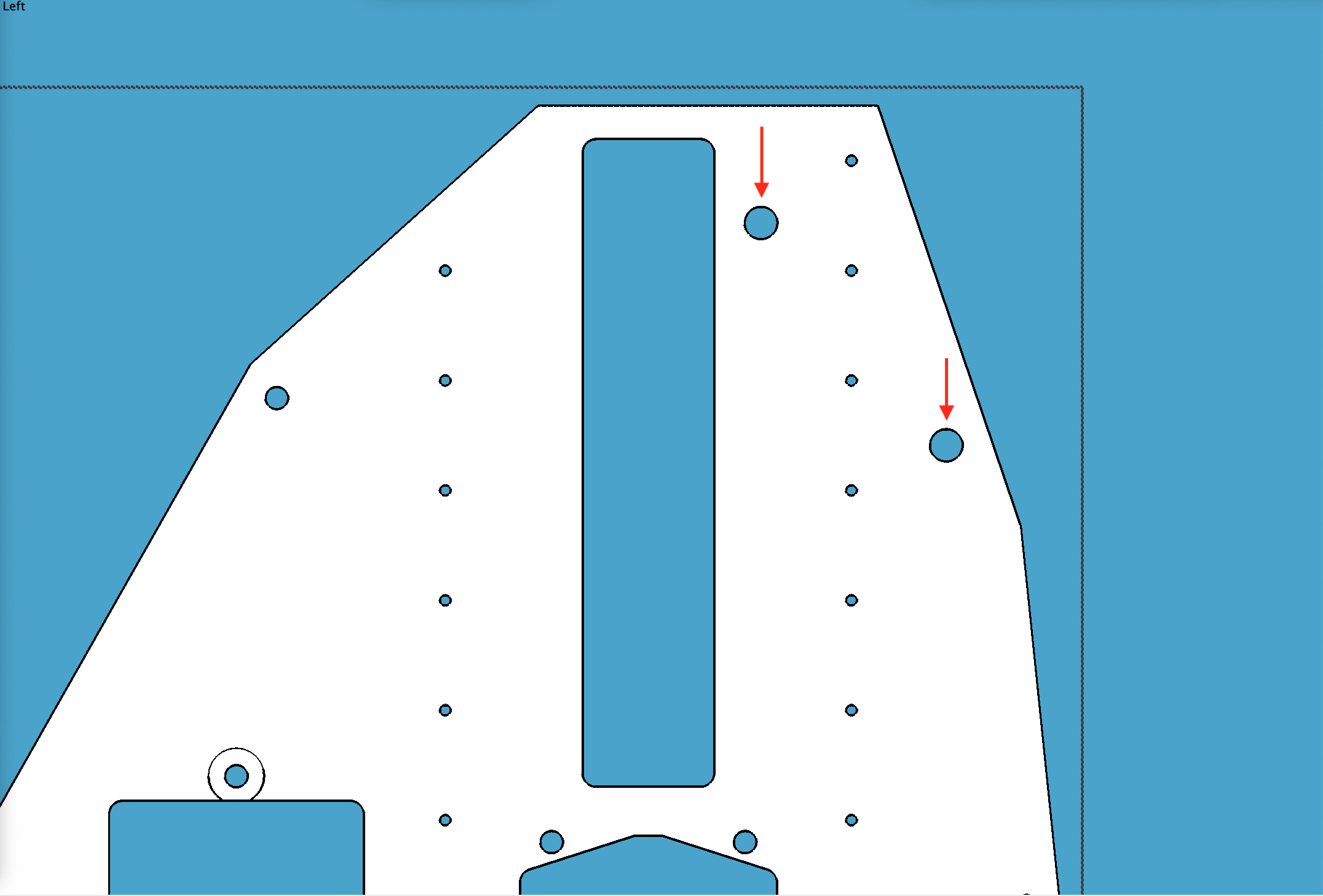
Before:
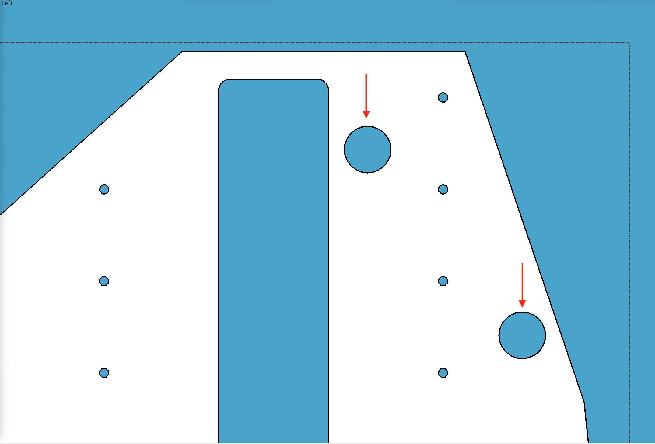
After:
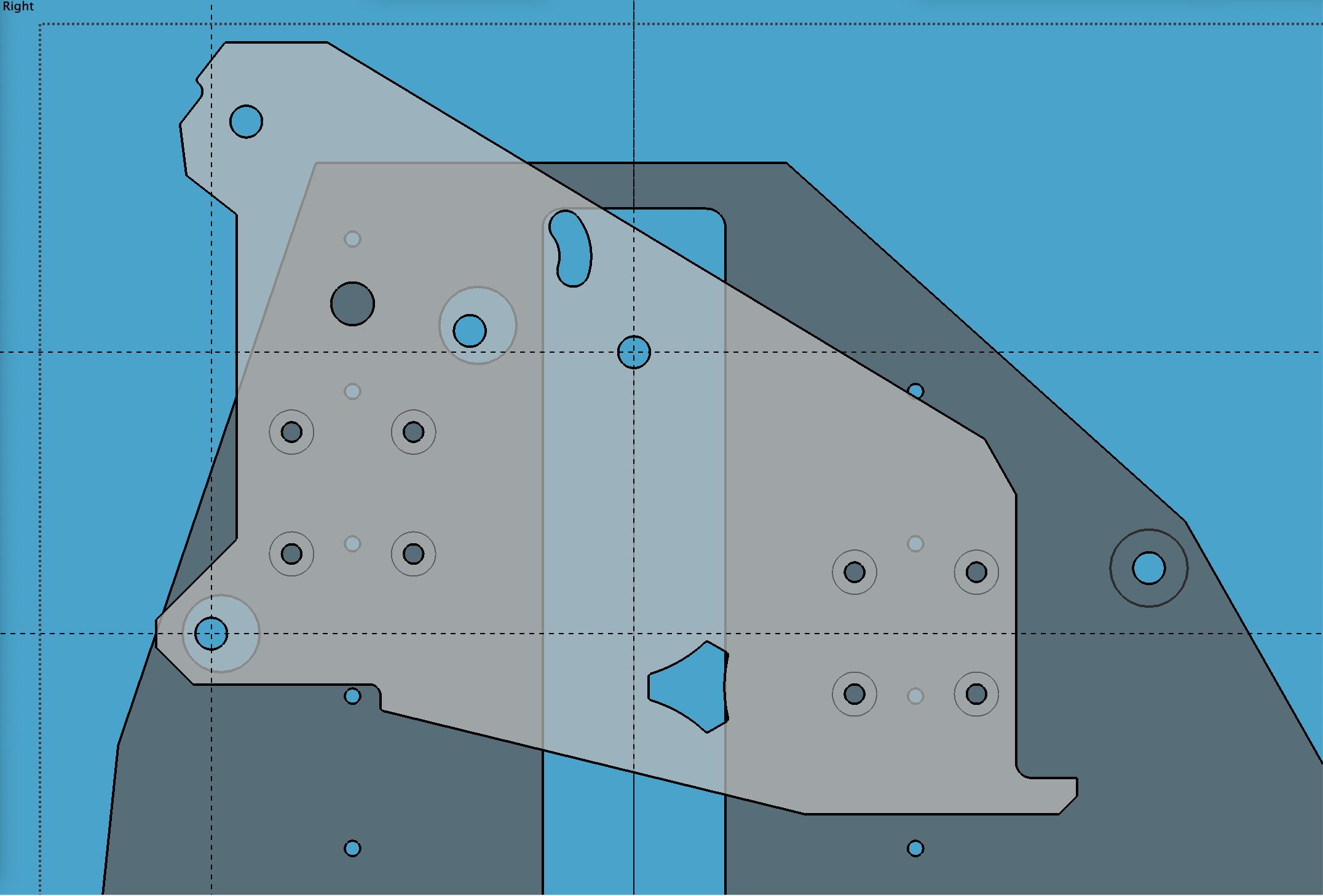
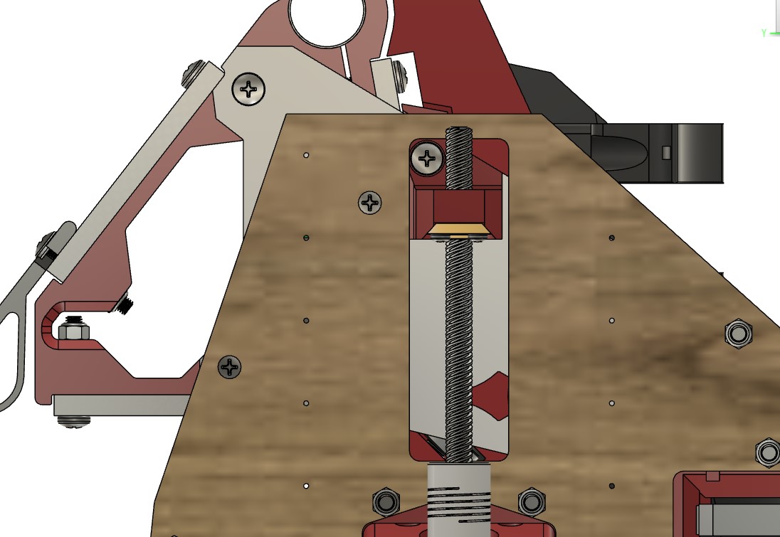
Also, you probably already know, but the “tool access” holes in the YZ plate don’t seem to line up exactly with the their corresponding screw holes in the XZ plate. This overlay illustrates it.
(This is showing Dan’s “tall” YZ plate, but the same holes on it are moved up by the same set amount as the rest of the plate part. It’s also showing the tool access holes already drilled out larger, as mentioned above.)
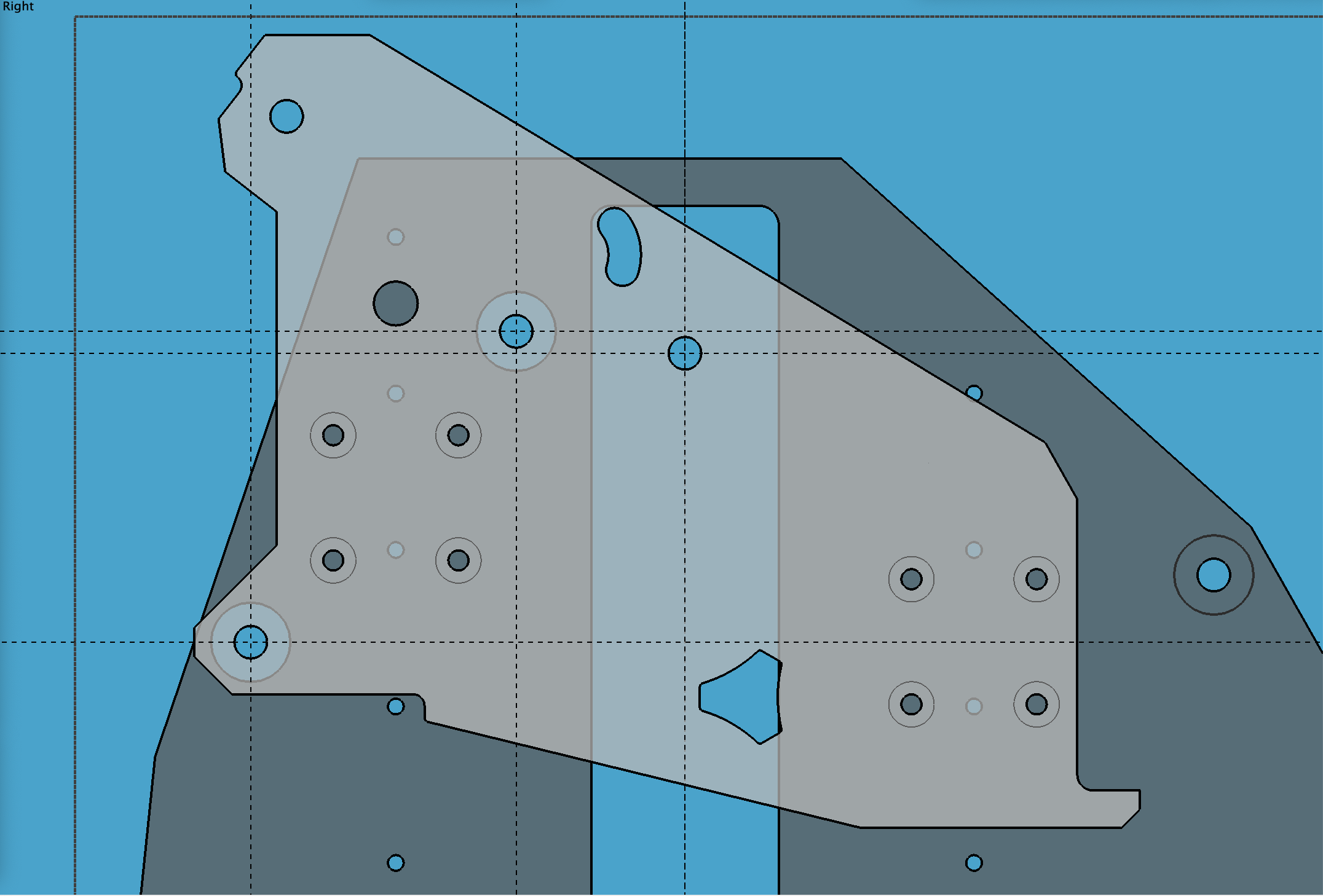
Finally, this revised overlay shows the tool access holes in the YZ plate, nudged to correspond to the screw holes in the XZ plate, as well as drilled out larger (1/2") for allowing screw insertion/removal.
I I can make the holes larger but I will also move them down a bit, great idea.
My models and assembly show centered holes.
I have used mine and they seem to be centered on the screws. My 3mm bit driver is a tight fit in those holes.
In my overlay “research” only one of the needed moved down. One was spot on from left to right. Both need moved to the side a bit to line up.
Hmm. Previously I created a vector based overlay showing original DXF and Dan’s DXF, and Dan’s holes seem to be aligned (horizontally) with the original holes, only moved up vertically.
I used Dan’s file to CNC cut my YZ plates (with only changing one profile line). I bought V1’s aluminum XZ plates. I used the drawing from Dan for the above overlay (YZ) (with only changing one profile line), and a downloaded V1 DXF (XZ) for the overlay. The downloaded V1 DXF was from here: https://docs.v1engineering.com/img/lr3/XZ%20Plate.dxf
… as linked from here: LowRider CNC V3 - V1 Engineering Documentation
(If I recall accurately.)
Use the linear rails small holes and the bearing block m3 holes as you fixed points to see if that fixes it for you. DXF’s can have odd points and the bearing holes are a good way to double check. Like I said I checked the CAD and the assembly, no issues at all.
I would move them down if I make the holes bigger to give the walls more meat.
.jpg)