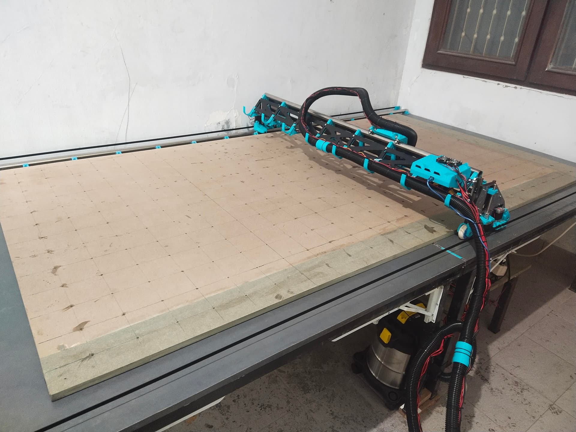
Finally got my LR3 hardware and table setup with few modifications, i’m using klipper and managed to make the XYZ axis, endstops working for now. With spindle and vacuum triggered by SKR Pro using SSR relay.
300 cm x 160 cm foldable table (mdf epoxy resin coated) with full sheet spoil board.
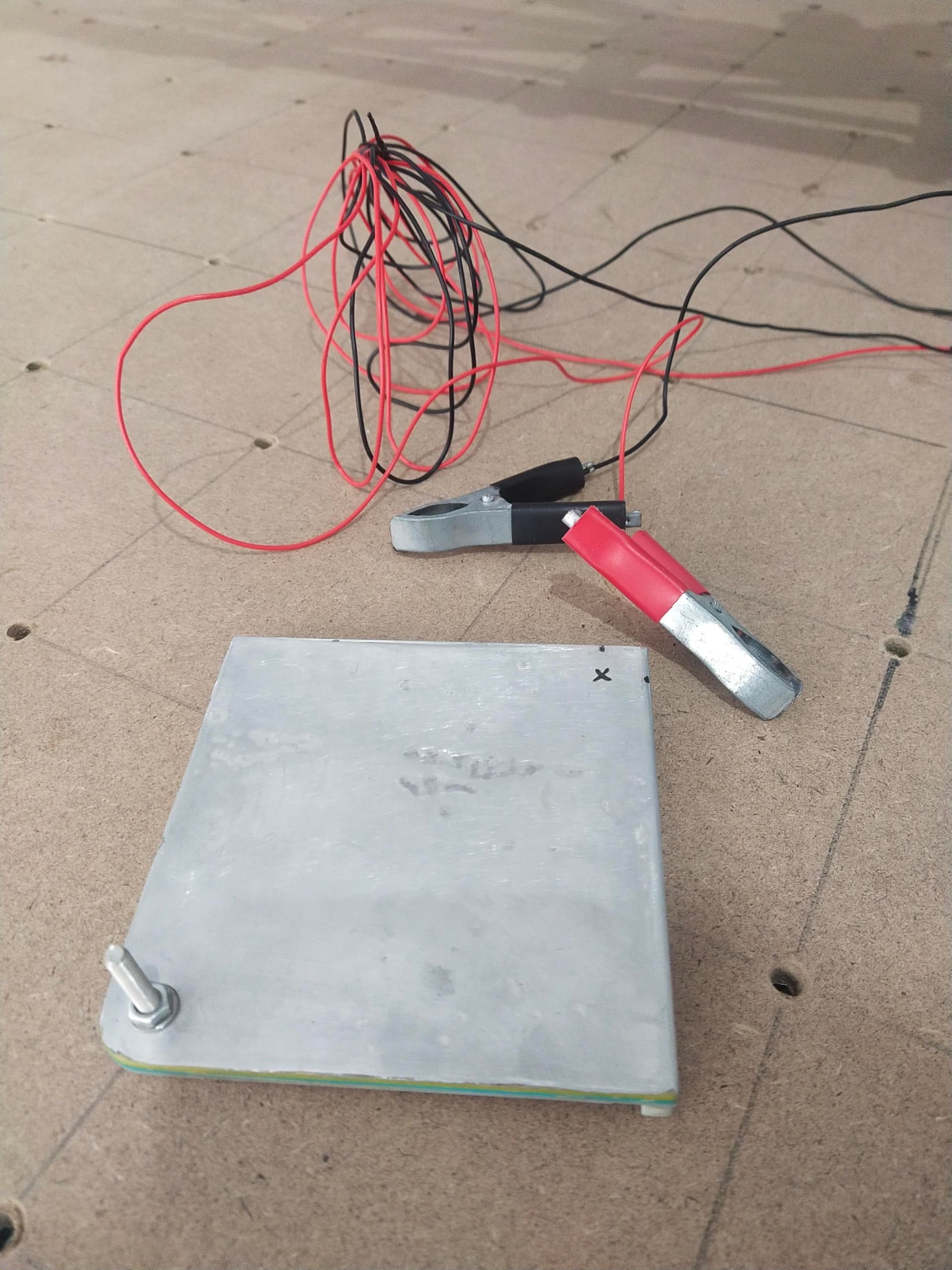
I haven’t tried milling anything yet, and am trying to figure out to the last part to add XYZ Probe and created a simple 3d printed XYZ probe plate coated with alum sheet. Wired it to and it works, i just cant figure out how to get the XYZ probing to work with klipper.
I saw some videos of people successfully using klipper in MPCNC, and it will be great if anyone experienced can share how i can get these working.
Now in case you wonder why i use klipper as opposed to marlin, i’m quite new to 3d printing and had only started one year ago, and started learning it in klipper so more familiar with it. I’m running 2 printer simultaneously with 1 Pi 3B, and trying to run LR3 using the same PI. (In case you wonder if it works, long cable pulled from next room, it worked but i think its not enough to run 3 machine at the same time)
I have few questions if anyone can help:
For the Z axis, the endstop is at the top. I’m abit confused as i’m used to 3d printing. I got z height of say 70 mm. Should the top endstop be 0 or 70mm? Because i’m trying to figure how it works when we have gcode run thought it and afraid may make the mistake and ruin my gantry.
a) If it’s 0 at the top, and 70 mm bottom, does that mean when we mill, it goes say from 0 to 10 mm progressively down?
b) If it’s 70 at top, and 0 bottom (i setup like this now), does that mean when it mills, it goes say from 70 to 60 progressively down? Which one is correct a/b?
Because in 3d printing, i got both setup, Z stop at bottom=0 (cartesian) or Z stop at top=0 (corexy). But milling is opposite of 3d printing as it mills from top, meanwhile 3d printing layers from bottom. sorry for these questions, i havent started in marlin and cant understand how it works.
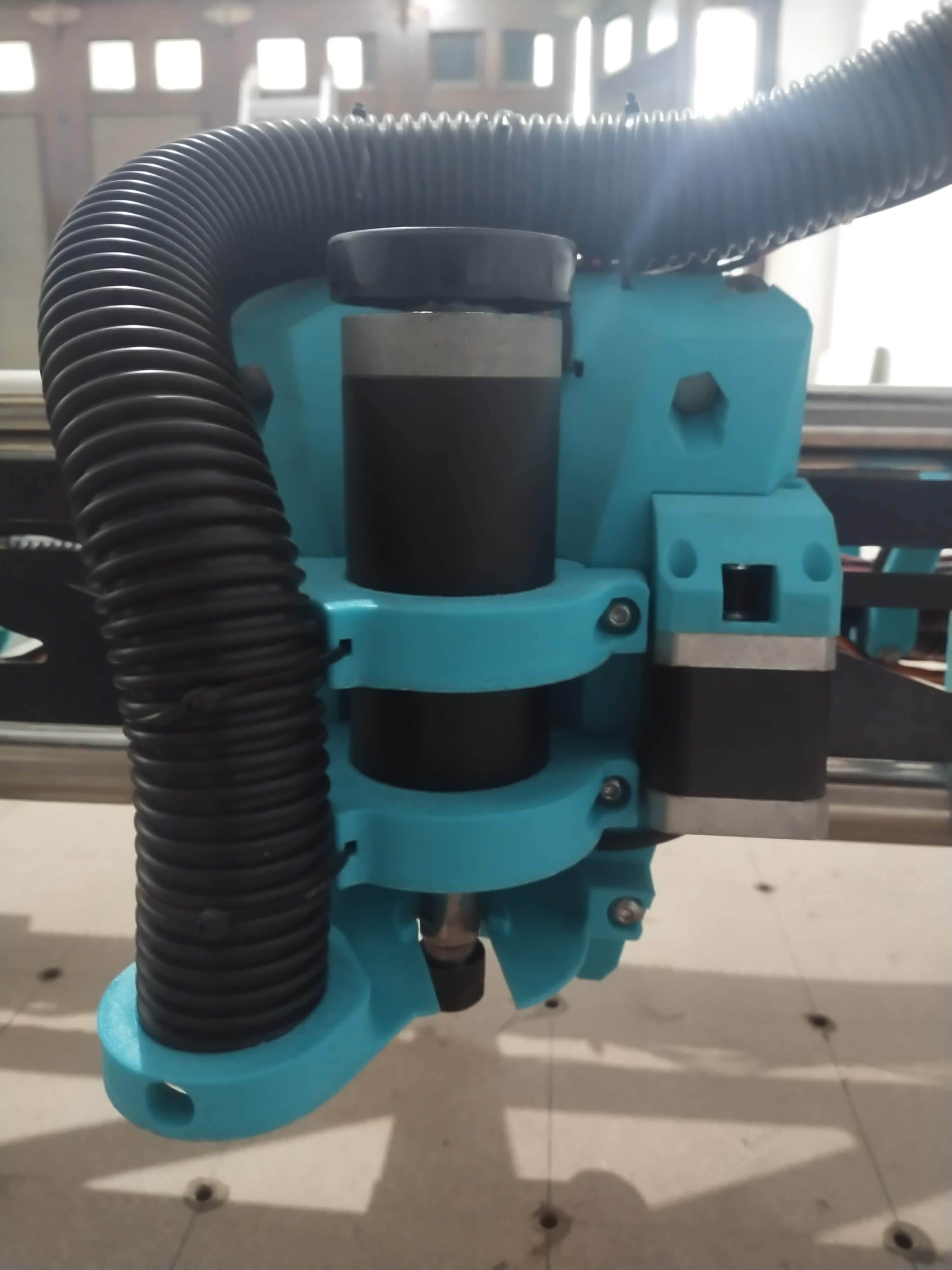
Please correct me if my understanding is wrong. For spindle, I have 48v rated spindle, and SKR Pro can only go for 24v. I can setup PWM directly to the spindle, but it can only go for max 24v? I cannot seem to find a way / device to trigger 48v using 24v pwm, so i resorted to simple analog switch using SSR, and using dimmer to control the spindle speed manually. Is there any device that is able to switch from 24v pwm to somehow control the 48v spindle speed using the SKR pro? Or only GRBL able to do that?
My last option is to go for Marlin and the pre built V1 firmware. (that means an LCD that i havent bought, and learn Marlin), but i really hope i can find someone that has got Klipper running that can help before i give up on it. Here are a few things i may need to solve:
b) Amongst those, to get the XYZ probe i need G38.2, but it does not seem to work and it links to other macros from the klippy-cnc (i don’t understand the coding inside the G38.2.cfg, only understand basic gcode macros and configuring the firmware configs)
Lastly, for the current V1 Marlin firmware, can we use the XYZ Probing? As i read so far its mostly Z probe. If anyone has done it and can share some guidelines / tutorials that will be great.
Sorry for the long post, i guess this is my important last hardware / software aspect i need to solve / decide on, before moving on to probably learning the cam software. I hope anyone experienced can share their experience before i discover deadends. Thanks you everyone
In Marlin, we have lower Z go down. The homing operation goes up on the LR. Marlin thinks the top is Z=200mm (which is wrong). But that is ok, because we force Z=0 later with a Zprobe, or manually with G92 Z0. I usually want Z=0 to be the top of the workpiece, but other people like it to be the top of the spoil board. You can decide for yourself, but make sure your CAM knows what you want.
b) My setup is zero at the top of the workpiece. If I am cutting 12 mm stock, I cut to -12.5 or so.
This depends on your spindle. Some spindles can accept a 5V pwm signal as control. There are level shifter circuits (and it would be a good idea to get an optoisolated one) if your spindle can’t. Be aware that the skr 24V fans and heaters don’t switch the 24V side, they switch the ground side. But you can use any 5V pin with a level shifter. Do your own research though. I don’t know your spindle.
I haven’t used Klipper for CNC. But I can say we don’t use most of those. A lot of those are to make it more like grbl. Most gcode is easy to read. It has some setup, it has a bazzilion G1 commands, maybe some special code for bit changes in there, and some finishing commands. You can look at the gcode in the test crown for example, or do some of the estlcam basics and see what that ends up as.
G38.2 is tricky. Because we use that in Marlin for the low rider. In our Marlin setup, that probes down, until the Z touch plate closes the probe endstop. Then backs off 5mm (IIRC). You can combine that with G92 Z5.5 to set the Z height to the top of the workpiece. You can spend as much time as you want working on macros. They are a fun part of klipper, IMO.
You don’t need any of that though. You can cut right away with G92 to force the Z to be zero while the bit is touching the surface.
You also don’t need the screen to run marlin. My current setup is octoprint and an skr running marlin.
Nope. Only XYZ homing and Z probing. XY probing isn’t that useful, because you still have to align the workpiece, or probe multiple points on an edge to adjust for twist.
An easy workaround is to use the CNC to cut some dowel holes in your spoilboard and then use the dowels to align the workpiece. It will be square and a known distance from the endstops.
Thanks Ryan. A lot of people may find it harder than Marlin, i guess because they are used to Marlin. I find klipper easy to use, as i have a fresh start. Kinda like how it is monitoring my prints with timelapses wirelessly thru phone.
And the best experience i had was that i turned my 10 year old crappy printer that was using Marlin that i gave up on, and manage to run it on klipper almost as good as my new coreXY Ender 6 only running on ramps mega.
Its cool that so far i only find V1Engineering using Marlin for CNC, and thats what actually got me started as its not too far from my basic understanding of 3d printing. When i read about it first time, i gotta build one for sure. If it was GRBL or Mach3, i think i would have passed.
Hopefully there may be addition to people who may use klipper on MPCNC or LR3 who can share as i saw some people who have done it.
Thank you so much Jeff for the clarification. That clarifies most of the things i have problem with.
So it shouldnt really matter i guess, i can easily switch it. Will test it out.
Ahh ok. I think my spindle are the basic cheap ones so shouldnt have that. But cool, will find out what are level shifter circuits.
Oh cool, so not really needed. Am not trying to make it like GRBL. Just probably some useful Gcodes i may need.
Z probe should be easy, not much different as using BLTouch etc. I dont use Octoprint as i think it may be heavy load on the PI after reading. So im using both FluiidPi and Mainsail in the same machine that i can switch whichever interface i like, to control as many device as i can. I had to figure that out the hard way as not much tutorial but work like a charm running 2 prints on budget.
Cool, thanks for letting me know, i just saw that XY probing looks cool and never tried yet so may proceed without that.
Thanks a lot for the ideas and clarification. I guess i should start without the G38.2 on manual for now to test how it goes. G38.2 is something cool that probably saves a bit of time for me to setup initially (like… after using BLTouch, never again im going manual levelling)
Thank you for the answers. If anyone interested in the configs to test do let me know. In the mean time, im gona try manually and hopefully have some other who can help with the G38.2.
There is some weird thing where the klipper fans (not really core klipper, mainsail and fluidpi fans) attack octoprint. But it isn’t slow or a heavy load at all. I run octoprint with my klipper and it is super reliable. It is a shame that they attack octoprint. They can do a lot more working together.
Oh i see. Octo have many useful plugins but i didn’t get to try them cause started on Fluidd and Mainsail. Not a hardcore fan myself, just reading and deciding on what to use early on. May want to try Octo later.
How do you setup octo and skr running Marlin at the same time btw? The firmware is Marlin right? Then what do you use Octo for if klipper not installed?
Is the G38.2 prebuilt into Marlin or you programmed into it?
Octoprint sorry of replace the screen. It holds the gcode files. It has controls to jog the machine. You can send clans and read responses on the terminal/console. You can set up macros.
Jamie made a cnc gcode preview plugin to make the gcode preview work for cnc gcode.
Marlin still does the heavy lifting. Klipper alone (the mcu and host code combined) is similar to marlin.
Octoprint and marlin are separate projects. I have one octoprint on my klipper printer and one on Marlin. They aren’t coupled like klipper and mainsail are.
It is built into the marlin firmware. We had to turn it on. The firmware at MarlinBuilder releases has it enabled (on the DualLR, at least)
My latest “revive” of the lowrider uses an skr pico with a raspi 3 running mainsail
Mainly because all my other controllers are dead -_-
The cnc support of klipper is very poor
No workspace support, custom homing IS difficult.
A lot of security features/functionnality orientations are heavily geared towards 3d printing
Moreover the dev team is not really interested in adding CNC features or even merging pull requests towards those functionnalities
Kevin isn’t interested in adding any functionality. He’d a very stubborn dude. I know a couple guys trying to get changes made to klipper’s pid tuning because it’s mostly crap. He doesn’t see the need to change it.
Hey hug3tz, I actually just finished building my MPCNC using klipper last month, so a bunch of this is still fresh in my memory
Here is my printer config that uses a touchplate for Z homing. Having a massive + and - on min/max for each axis is important since we are using a G92 to set the workspace offset. Also notice that the homing_positive_dir parameter. If this is not done, your z axis will want to move up to home instead of down.
I home at X=0 Y=0 Z=0 of my spoilboard because in my fusion 360 CAM setup i specify the size of the stock. I use the MPCNC klipper post processor for fusion360 found by going to github and searching for cristianku/mpcnc_config (new fusion 360 post processor folder).
In fusion 360 i made sure i specified my stock size and set the start position to the bottom left of my stock (not the workspace)
My standard workflow looks like this
home xyz to 0,0,0
jog router up and to the bottom left (x,y,z =0) of my stock
use G92 to set the workspace origin
run the program
hope this helps! let me know if you have any questions and i’ll try and help the best i can.
For anyone interested, this is my Klipper config for LR2 with SKR pico
Using a switch endstop for Z, and sensorless homing for X/Y
E0 output is mapped to Y2, and using the dual z motors in parrallel…
# This file contains an example configuration to use a PWM-controlled tool
# such as a laser or spindle.
# See docs/Using_PWM_Tools.md for a more detailed description.

[output_pin TOOL]
pin: gpio20
pwm: True
hardware_pwm: True
cycle_time: 0.001
shutdown_value: 0
#maximum_mcu_duration: 5
# Default: 0 (disabled)
# Amount of time in which the host has to acknowledge
# a non-shutdown output value.
# Suggested value is around 5 seconds.
# Use a value that does not burn up your stock.
# Please note that during homing, your tool
# needs to be in default speed.

[gcode_macro M3]
gcode:
    {% set S = params.S|default(0.0)|float %}
    SET_PIN PIN=TOOL VALUE={S / 255.0}

[gcode_macro M03]
gcode:
    {% set S = params.S|default(0.0)|float %}
    M3 S{S}

[gcode_macro M4]
gcode:
    {% set S = params.S|default(0.0)|float %}
    SET_PIN PIN=TOOL VALUE={S / 255.0}

[gcode_macro M04]
gcode:
    {% set S = params.S|default(0.0)|float %}
    M4 S{S}

[gcode_macro M5]
gcode:
    SET_PIN PIN=TOOL VALUE=0

[gcode_macro M05]
gcode:
    M5

[gcode_macro SET_ZERO]
gcode:
    G92

[gcode_macro LASER_POINTER_ON]
gcode:
    {% set S = params.S|default(1)|float %}
    M3 S{S}

[gcode_macro LASER_POINTER_OFF]
gcode:
    M5
Wow, this looks fun. I just made both printers klipper. I may have to try my cnc now! I have klipper runing on an old dell so plenty of room to add it!!
So @jeffeb3 I am putting some thoughts in my head. If a cnc is klipper enabled, can the heightmap make a cut on a roundish object? If say a cnc had a height probe like a long bl touch? How much can the heightmap measure for bed mesh? Wow, i hope all that came out correct!
Did you get it working? The macros are all there and I think next weekend, I may try this. All though I am hesitant as I am running Ramps and not sure I really want to try the ramps board and Klipper.
Those CNC macros look like it would make it work well.
I would really like it if I could easily take a gcode file and generate the correct probe command to make a mesh that covers that area alone. Then that mesh would just be the top of the workpiece. I would use it every time.
So headed to mrrf this weekend, but I am running a ramps 1.4 board, any pointers on where to find a klipper cnc profile for the mpcnc? I may just have to try it and see where I get.
