Are you running the T8 lead screw, or a threaded rod? Can’t tell for certain from the picture above, but if you are running the threaded rod with the T8 firmware, your steps/mm will be way off and the Z will likely look like it is not moving at all during a lift and cause the exact problem you are having with the bit dragging through the material instead of lifting and lowering to start the cut.
1 Like
i buy everything on December 29, 2016 (vicious shop)
because labor issues this last month I could have more time and finish my MPCNC. I think my firmware is the old one, MPCNC813_GLCD , is the one that I just installed.
Apart from the repetier host, there is some more program
CAM, to control the machine, like the mach3.
now I will keep trying to make it work soon.
Stick to the recommended software until we get you working correctly. Try to go out on your own using other software will only frustrate you as I will not be able to help.
1 Like
OK. Be sure, as in your earlier post you said you installed the T8 firmware, which would cause the Z issue you described!
1 Like
Sorry, copy and paste problems.
What I meant was that my Firmware was the new one for the T8 screw.
But in reality, the one I need is the old for my “5/16” Leadscrew "
Which I already have installed and running, fix the problem.
Now I’m focusing on fixing the cables a bit and improving the aesthetics of my machine.
In shortly i will upload a copy of my G code for a file I want to try to run.
ok, this is the file I’m trying to recreate, design and export from Corel in DXF. 30 x 30 centimeters.

Here is the G-Code
CUADRADO.gcode (55.1 KB)
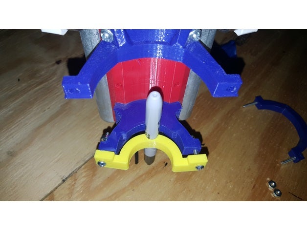
I placed the sharpie’s point, right where the purple X is, once started it moved to a corner, then it came back and started to run.

How did you make the gcode? The problem is definitely in the gcode.
G00 X0.0000 Y0.0000 Z0.0000
G00 Z1.5000

;No. 1: Engraving 2
G00 X482.7307 Y453.1098
You’ve got your origin set to the lower left corner, and you’re drawing way over at 482,453.
The process I normally take (and I assumed you were taking, because it’s pretty common) is:
- Make the lower left corner of the thing you’re drawing 0,0 in CAM
- Go to the place on the workpiece (in this case the paper) where you want the lower left corner
- Reset the home offsets (or just power cycle the arduino) to make the current location 0,0,0 in the firmware
- print/run gcode
If you want to do it they way you are (where the gcode defines where in your CNC workspace the paper is) then just remove the line G00 X0.0000 Y0.0000 Z0.0000 from the gcode.
The reason you would want to draw at 0,0,0 and reset the origin while at your workpiece is that it’s much easier to locate the paper in your workspace.
1 Like
Thank you very much for the help of all, it is already working correctly.
I have a small Z problem but it is because of the bed or the legs of the machine.
But it works. 
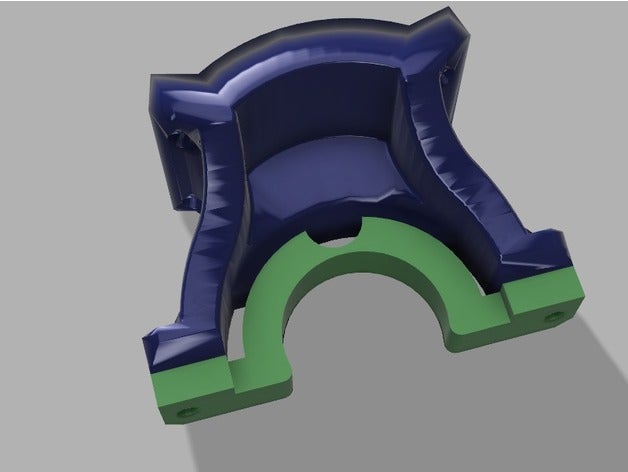
During the test, i design a sharpie mount that is a bit more easy to use and put on.
It goes on top of the “Ryan” Dewalt Mount 660.
Thanks everyone for your help !!!
shortly I will continue bothering haha …
Marcos

The pen mount I made has a built in spring to ease the use of a pen on an non-perfect bed, and won’t mash the pen tip. That should take care of your issue.
1 Like
Hello, Today I finally try my first cut, I already have my machine pretty clean visually and fixed.
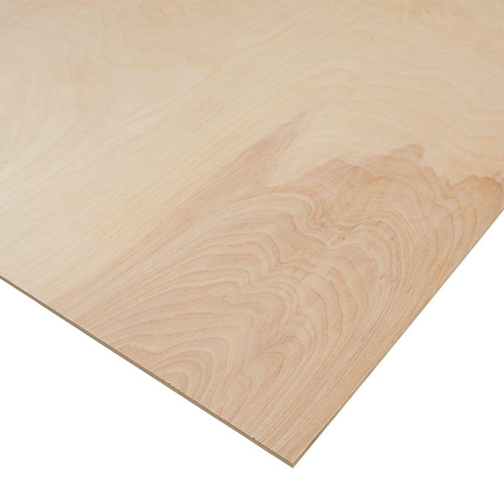
I bought these bits and Plywood
HQMaster 1/8" Shank Single Edged 1 Flute End Mill CNC Cutter Spiral Router Bits Cutting Milling Set Tool Carbide Tungsten Steel Upcut Bit 17mm CEL
- 1/4 in. x 4 ft. x 8 ft. PureBond Birch Plywood
but everything ended very badly
This was the drawing I wanted to make.
https://photos.app.goo.gl/9QT1AGh0Z30Qkc0P2
G-CODE
Project podstavka
;Created by Estlcam version 10 build 10.047
;Machining time about 02:01:28 hours
G90
M03 S24000
G00 X0.0000 Y0.0000 Z0.0000
G00 Z1.5000
;No. 2: Engraving 7
G00 Z0.5000
G01 Z-1.0000 F180
G01 Y82.9662 F480
G01 X89.2823
G03 X61.6083 Y53.2829 I2.0826 J-29.6836
G01 X61.6119 Y52.8154
G03 X121.0000 Y50.5912 I29.7532 J0.4673
G01 X120.9534
G00 Z1.5000
G00 Z-0.5000
G01 Z-2.0000 F180
G01 Y82.9662 F480
G01 X89.2823
G03 X61.6083 Y53.2829 I2.0826 J-29.6836
G01 X61.6119 Y52.8154
G03 X121.0000 Y50.5912 I29.7532 J0.4673
G01 X120.9534
G00 Z1.5000
G00 Z-1.5000
G01 Z-3.0000 F180
G01 Y82.9662 F480
G01 X89.2823
G03 X61.6083 Y53.2829 I2.0826 J-29.6836
G01 X61.6119 Y52.8154
G03 X121.0000 Y50.5912 I29.7532 J0.4673
G01 X120.9534
G00 Z1.5000
G00 Z-2.5000
G01 Z-4.0000 F180
G01 Y82.9662 F480
G01 X89.2823
G03 X61.6083 Y53.2829 I2.0826 J-29.6836
G01 X61.6119 Y52.8154
G03 X121.0000 Y50.5912 I29.7532 J0.4673
G01 X120.9534
G00 Z1.5000
https://drive.google.com/open?id=1_WevulOhapt07O0KFQQBts2eO2RqDd5z


I can’t access your gcode, you can just upload it here.
You built an absolute monster of a machine your gcode is going to need to be pretty perfect. That looks to be double the recommended size in the X, Y, and Z axis.
In the beginning until you really know what you are doing you should start with drawing it with a pen, then try the exact gcode in High Density foam, then to wood if it is correct.
Also stick to the corners when possible on such a monster build.
How did you generate that file it is not correct.
It has no info header and it has no rapid feed rates set. It will never work. I can;t help without knowing what you used to try and make that file.
1 Like
Ok, I understand that 4 x 4 feet too much, I was looking for a machine to do some work in my house.
I upload the settings I have in the Estlecam.


I wanted to do some work similar to these sizes and designs.
In your experience, if under the size at 2 X 4 Feet? i would work? , would have the robustness.
The Z axis is in 200 millimeters.


4.png - you are using estlcam firmware. That is your issue. I do not support that as too many people have issues. Please use my firmware. Suspect you have not have your settings correct on the 4.png page.
A 200mm Z axis as a router is a bit out of the question really, sorry.
As for the giant cuts I made the LowRider specifically for that.
Here is some info,
I have some size info on the second or third paragraph.
https://www.v1engineering.com/specifications/
This is the more direct size page,
https://www.v1engineering.com/assembly/machine-size/
A little more here,
The gcode you sent me does not look like it was generated by the version of estlcam you have in the screen shots.
You are showing rapids settings but the file does not have them and also does not have the estlcam header either.
1 Like
For example if you wanted a half sheet wood router you will be fine if your cuts are 2D cuts all the way through, to compensate for any loss in Z accuracy just cut a bit deeper . You can go even bigger if you keep this in mind and use mid span support on the outer rails to supplement the rigidity.
I’m not interested in 2.5, only in 2D… I use Stelcam only to general the G, then Repetier to take the G and export it to the SD-Card.
I’m in love with my machine. is beautiful, I know I’m bored, I apologize, I just do not want to throw away my investment.
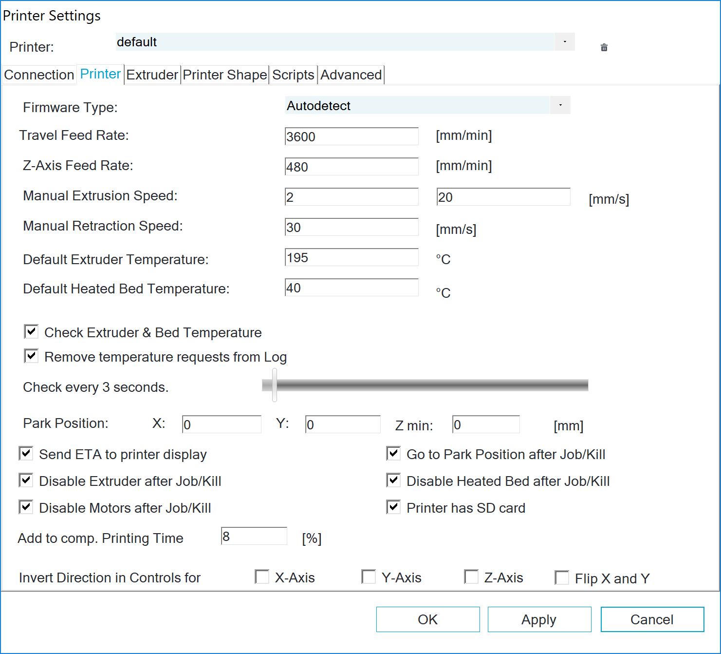
The file you have now cut and pasted above, is not matching the settings you show in 3.png. I would go through my setup one more time and look for any missed checkbox or info. You have to have a speed on every line, the “F” command.
1 Like
Watching that video though, it looks like your about to catch fire and you’ve either got a dull bit, or your cutting waaay to deep. Your gcode is trying to cut 1mm deep, so I think your bit is dull. I don’t think it’s a depth issue. You’d have to get pretty deep to have that big of a mess. I think you need to buy at least one nice bit. If you have a good bit to compare to, you can immediately tell a crappy one. If it’s really wobbly, it’s possible you’re digging too deep, because the bit will try to pull you in.
W.R.T. build size, I agree that you’re starting it the hard way with that big of a build. I think this is a problem you can fix, but after that you might be upset with the precision at that size or you’ll get more failures when you try to go deep. Some alternatives for the projects you posted: 1) Cut thinner templates and trace with a pattern bit in a handheld router. 2) Make your MPCNC smaller, and combine the parts as a template or for the final work. 3) Build a low rider. 4) Shrink the mpcnc and find creative ways to work on the project boards one section at a time, by hanging the board off the side of the table.
In the end, here’s my advice. If you’re having fun, then keep having fun. Buy a new bit. Measure the depth of that cut you made. And if you’re still having problems, try to think about this first setup as a way you can hone this new craft. Shrink the CNC. Learn CAM. Get some neat, smaller projects cracking (the lamp shades can be done smaller), and then expand to the huge size and at least know what you’re getting into.
1 Like