He has helped me but is a busy guy, Has been very helpful with near step by step, if he could have reached over and wired it for me im sure he would have haha.
I have opened up #define SERIAL_PORT_3 3 #define BAUDRATE_3 115200
Matching with:
Serial.begin(115200); //Baud Rate
on Arduino
I have plugged in the UART correctly, it turns on. Ive swapped pins with the rx/tx but what other options could i have with this board to get it to work? originally it was to be plugged in with the TFT but using touch screen. Any other input on it?
I don’t own this board, so I don’t have an answer for your question, but I have a couple of questions. First, why did you select 115200 as the baud rate when the default baud rate for Marlin is 250000? Second, did you do anything to prevent sending 5V signals to the 3.3V pins? I’m assuming the RX and TX pins are 3.3V.
i have tried both Bauds independantly, 115200 / 250000 on the serial port_3 3 and pendant. I have tried swapping the rx / tx in a chance i had swapped wiring, Which i dont believe i have. I was told it doesnt matter with the Arduino and the UART as long as they are matched. It may be the type of Arduino i picked as i ordered wrong one to start with.
You very well could be right about the pins being 3.3v? No i didnt do anything i assumed they were 5v, 5v power to Arduino and same to board. Would 1.7v make a difference? It should work still on that logic, if anything fry the chip or screw the port.
When i plug the pendant into the pc and look up the ide serial monitor everything functions as it should.
When its plugged into the serial Port defined for UART, the pendant powers up but get nothing out of it. All buttons and LEDS light up. No way to check if its sending anything from the pendant to the board if i was to plug in a pc to the board?
The original maker runs his pins 5v to the board (Skr 1.3 ) but to his TFT port. Which is 5v. So what other options would i have to connect this to a available 5v serial pin while using a touch screen, do i need to put a regulator in to go down to 3.3v for UART?
(Dismark that last question, ill leave it here but i see the answer already lol that wouldnt work as not enough voltage to run it im guessing)
So my other option is to open the port serial port_3 6 and reflash config_h to gain a true 5v power supply?
Typically, it is bad to feed 5V to a 3.3V pin. It tends to burn them out. You only need to worry about the TX pin on the Arduino to the RX pin on the control board. If you are reading from the control board, feeding 3.3V signal to a 5V pin on an Arduino has always worked for me. I’m only a hobbyist with electronics, but I’ve used a simple voltage divider circuit when communicating between two Arduino boards of different voltages…just takes two resistors.
I’m a bit confused by all of your testing. Do you have Serial3 up and working or are you looking for a solution? Support for a 3rd serial port was only added to Marlin recently.
It may be the type of Arduino i picked as i ordered wrong one to start with.
So what board did you order to begin with that was considered “wrong?”
Im a novice at most. lol
Well the 5v is only getting power from the board so i guess would be under powered, so its only powering to 3.3v, the Arduino isnt plugged anywhere else for power. Im guessing thats the issue is not enough power to send back and forth.
I’m a bit confused by all of your testing. Do you have Serial3 up and working or are you looking for a solution?
Serial 3 is up and working or else there wouldnt be power going to it?
i enabled it in firmware / recompiled / uploaded to board etc
Well now that you pointed out that the port is only 3.3v that may be the issue. It would be enough to light the LEDS but would it be enough to run it all? im not sure, will need to test more.
I may give the other combination a try to see if 5v is needed, Just a wire jumbo going from 5v bl touch and some from WIFI port. (SERIAL_PORT_3 6 in firmware)
In the IDE software on pc with the pendant plugged into usb it funtions as it should in serial monitor. Would i be able to do the same with my board plugged into the pc with pendant attached to see if its even doing anything at all?
Im not very techy when it comes to this haha.
In the instructions it was called for a Arduino Nano, Some of the code had to be edited to adapt using the board i ordered which was a Arduino Pro Micro - it had less pins then i needed, lost a LED and had to map different pins. So may be the issue also in the coding possibly.
I built my own pendant for my Rambo board using an Arduino Nano. The project had some rough edges, and I never spent the time to smooth them out, so I’ve not published it anywhere. But, when pendent projects come across the forum, I always take an interest. In your particular case, I don’t have a SKR Pro board, and other than reading other forum posts, I don’t know the specifics of getting Serial3 working.
By working, I mean are you able to successfully send commands to the SKR Pro board from your pendant? Having the Arduino powered up does not mean working.
Well now that you pointed out that the port is only 3.3v that may be the issue. It would be enough to light the LEDS but would it be enough to run it all?
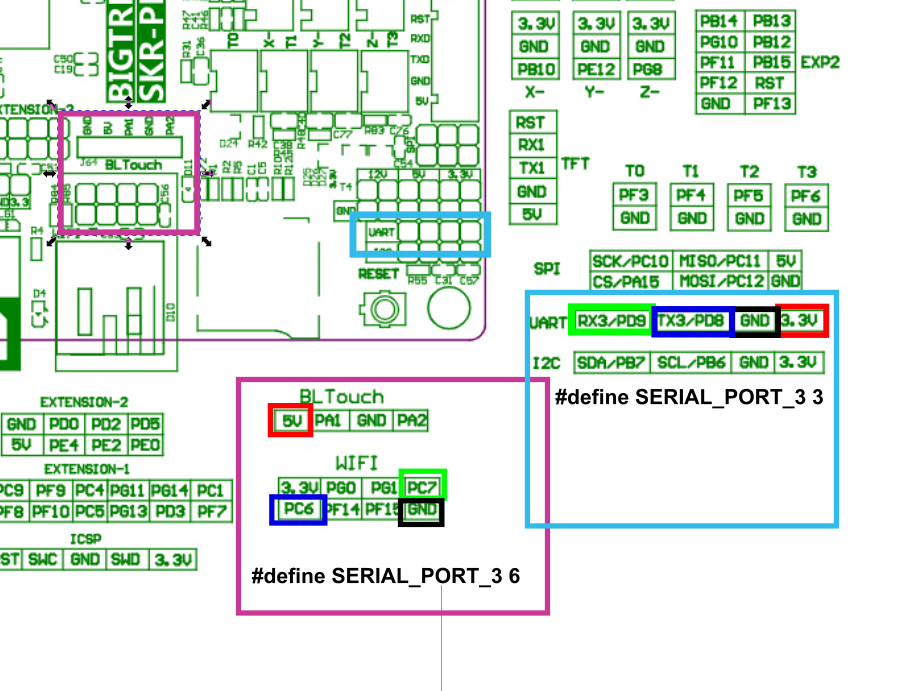
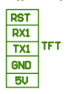
There are 5V and 3.3V pins on the SKR Pro. I doubt your Arduino would power up with 3.3V. I’m guessing some of the pins on the SKR Pro are 5V tolerant, but I don’t know, and even so, I don’t know if they all are. For example, look at this block:
It is a good bet (though not certain) that the RX1 and TX1 pins are 5V tolerant.
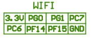
I’ve seen a post on this forum where someone was using the WIFI connection for serial communication (not for a pendant). Looking at that block:
Given the 3.3V in the upper left corner of this block, I would be reluctant to feed 5V signals to any of the other pins on this block. As mentioned in my previous post, if I was trying to communicate to this block, I’d use a simple voltage divider to bring the voltage down, though there are specific (and inexpensive) components called level converters for this task.
If you don’t have it working (as in able to drive the control board), then the place to start is to make sure you have all the firmware and connections working correctly. I would:
Using the Arduino IDE, open the serial monitor and use your pendent. With your board connected to your computer, verify the g-code commands are being sent after your modifications to the firmware on the Arduino board.
Change the baud rate to 250000 and hookup your pendant to the TFT RX1 and TX1 pins and get it working. You know these pins are enabled, since your TFT uses them for serial communication. You can put your display in Marlin mode if you need a screen. In Marlin mode, the cable to the TFT pins are not used. Note that TX → RX and RX → TX between the two boards.
Once the above two steps confirm that you have all the other potential problems solved, then go and explore Serial 3. It is possible that you’ve already burned out a pin or two…or not. You can get some verification that the pins are good by carefully hooking up a multi-meter to each pin and ground and using an M42 g-code command to set the pins high.
In my experience, 3.3V and 5V on a “high impedance” input like a uart is fine. If you were making a board professionally, my guess is most peers would think it was dumb. But for one board, it mostly works fine.
I have also seen a resistor put in series and that was enough to make both chips happy. Any extra voltage would turn into a small amount of current through the resistor and the chips can manage just fine.
When I have done that and been wrong (which is not recently, we live in the future ). The smoke let me know I made a mistake.
The next thing I would do is just use a uart to USB adapter and make sure the port on the skr works.
I didn’t succeed with UART coms when i was trying to debug GRBL HAL for the SKR Pro, but now i think we might change some configuration in marlin i wasn’t able to find.
From what i read Marlin can only handle 2 serial port at a time so activating SERIAL3 would mean to disable the screen or the USB.
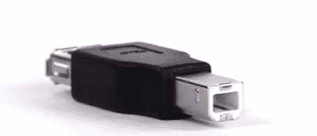
What about uing the uart to USB associated with a type-B usb adaptor(i think the other port on SKR Pro 1.2 is for host usb only like storage usb keys) ?
I figured out the issue. With the nano the serial pins and the USB serial both use “Serial.begin(250000)”, with the pro micro i needed to specify “Serial1.begin(250000)”. This one had me stumped for a few days.
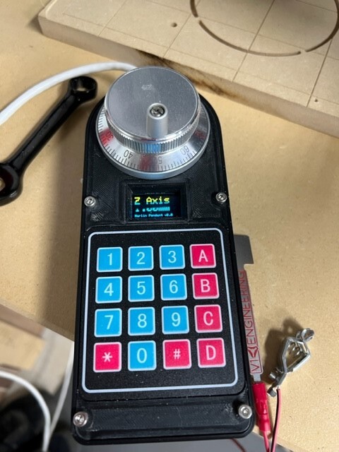
Great pendant, works perfect with the SKR Pro v1.2 board running Marlin FW. I ordered the blue and yellow OLED. So I’ll be changing the code so the yellow and blue OLED looks better. As well I want to add a few custom Gcode macros for my setup.
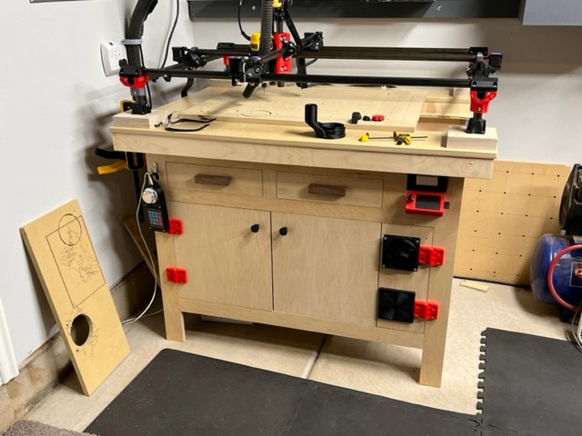
Orob, so by design the build is 24” x 36” (approx 610mm x 914mm) workspace. However the actual cutting area ended up about 22” x 34”. I loose a little with vacuum attachment etc. It hasn’t been an issue so far though. And I could remove the dust shoe and gain it back if needed. So far I have not cut anything larger than 20” wide. The cabinet is made from Maple plywood, drawer pulls are walnut, and table top just under the waste board is mdf. Thanks you.
 ). The smoke let me know I made a mistake.