Ohh I see, yes ofc, I’ve made sure to use 1.5mm2 wire, properly crimping it at the end etc. dw I wont try to power the psu with some 30awg wire lol
Made some PC cables last year and was trying to figure out how to get the thinnest crosssection wire without burning everything, almost went down to 22awg but decided It wasnt worth the risk.
Noted for the psu rails, so just two wires to the 11A inlet of the ramps would be good right?
No need for two directions on the spindle, it will translate to linear motion anyways!
Power rating as in amps? If so no clue, will need to ask the manufacturer, 0 documentation on the motor…
Is it possible to do the 24v and 6v rails thing?
Forget the neopixel then, id rather make my own ring light anyways so ill go with these mounted on a 3d printed ring basically, this way it will be exactly as i want it to be
EDIT 1: Planning to add a small peristaltic pump too actually
Man it sound’s like your building a torture device or something
So let’s see…
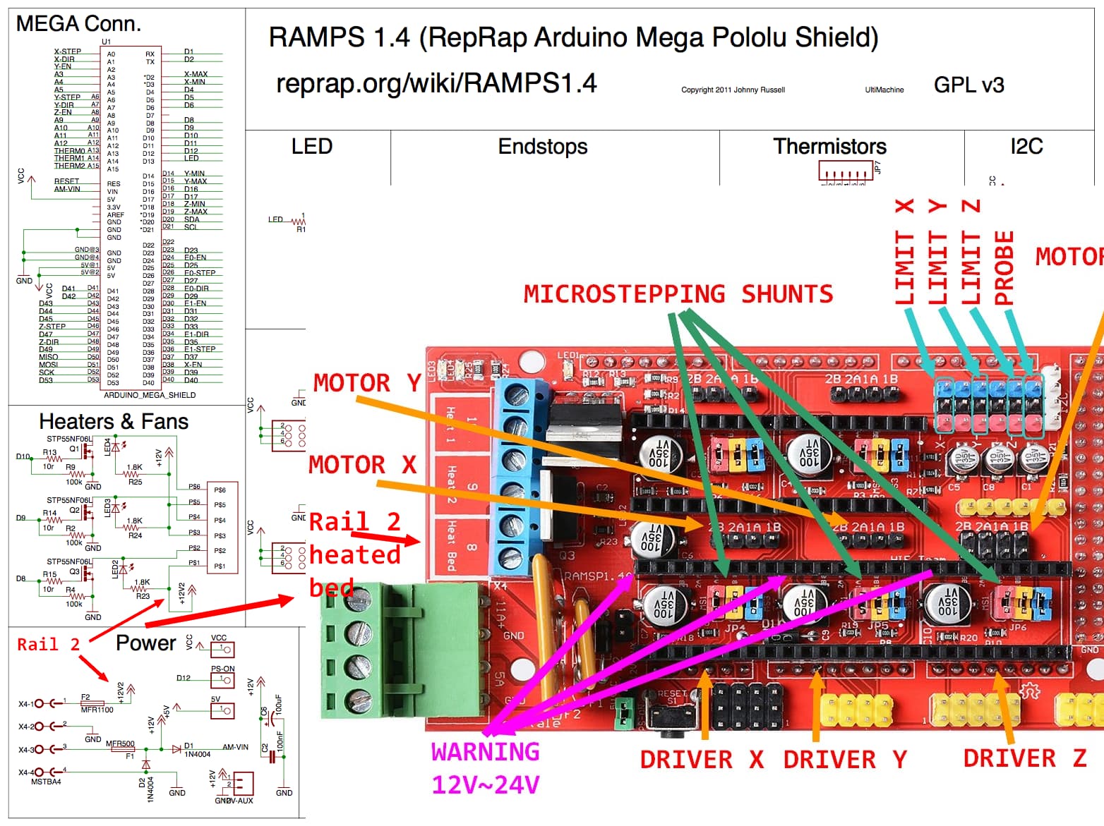
If you account for the 3 stepper drivers you’ll be powering up (that will draw no more than 1 to 1.2A each and not all the time) you can see that your safe.
EDIT: from that same schematic you can also see that the rest of the board is powered by the 12V rail (rail 1). That is the steppers and the heaters 1 and 2.
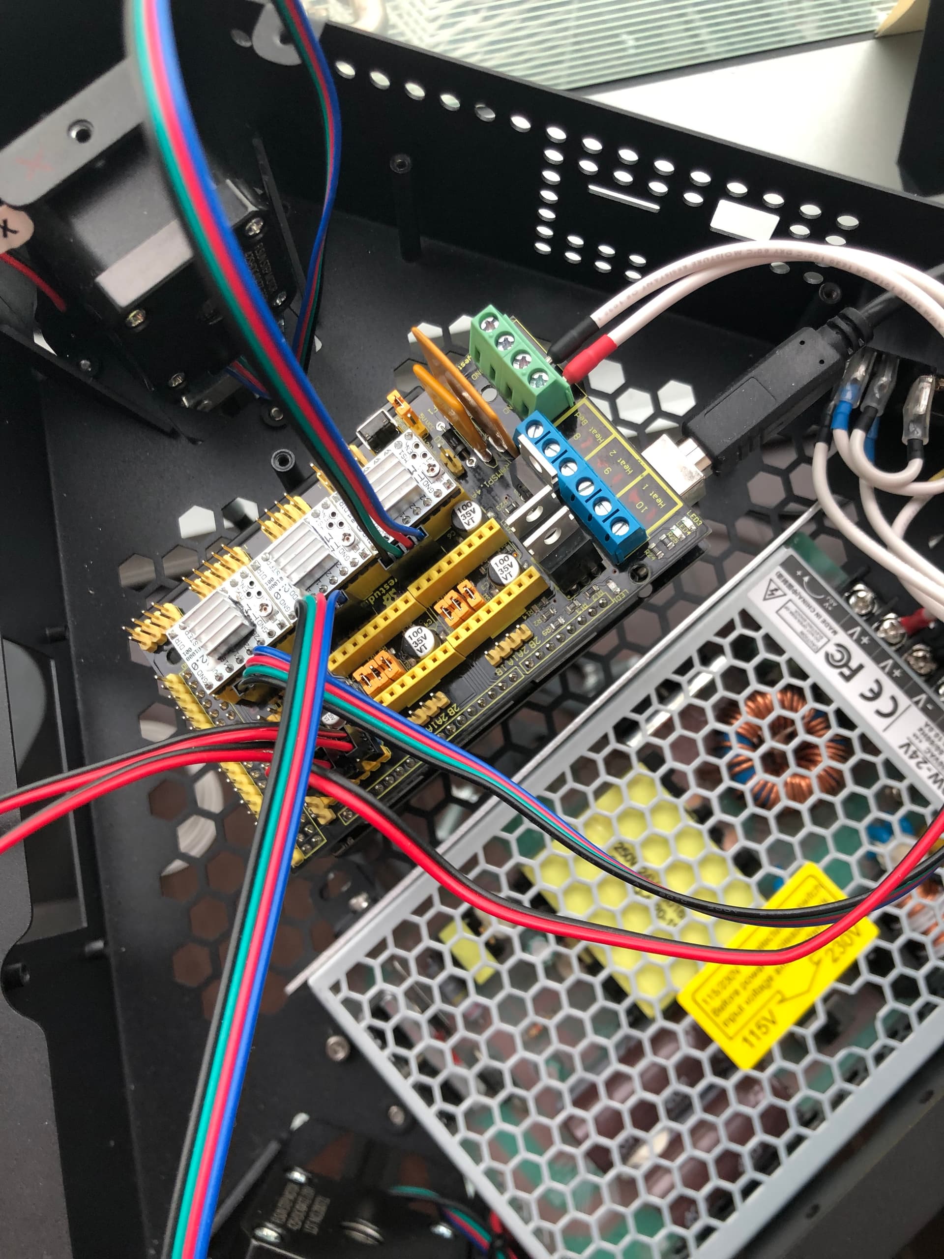
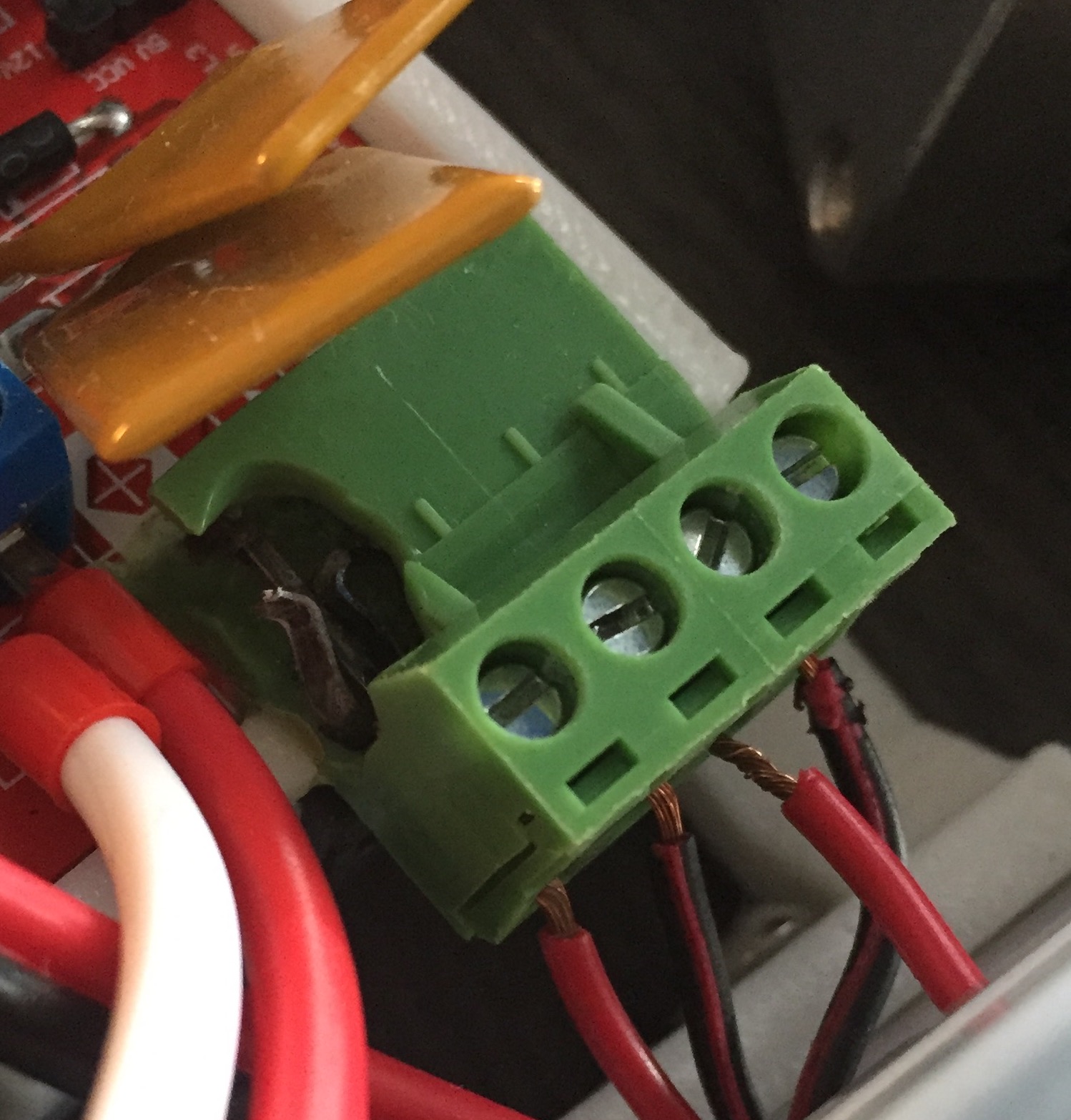
By the way just an advice if in the future you plan to reuse this board on a 3D printer. Replace that green power connector you see in the picture by a better one. That slide connection is pretty crappy and is one of the main causes of fires on these boards. For your current application is just fine since this is all low current stuff. Mine melted and almost got on fire good thing I noticed on time.
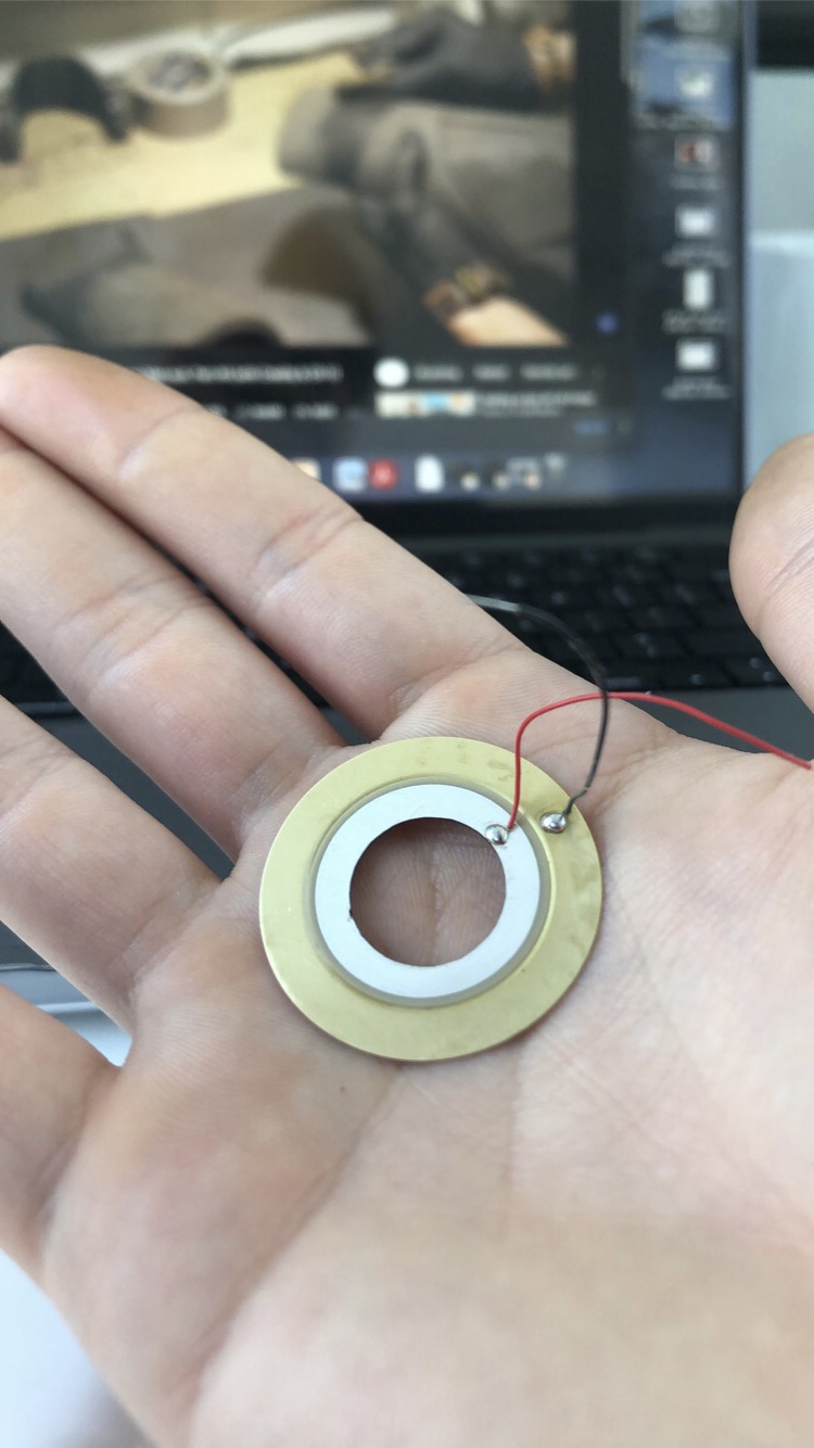
EDIT2:By the way in what type of laser/power did you cut your piezzo discs?
ok cool i see, which means that it will be limited to 6V/or ranging from 4 to 7V lets say through software? or do i need to change some components?
any info on which one? saw that it can cause a mess on some other posts…
itd be good to change it now and forget about it
150W KERN Optiflex CO2 laser, obviously at work as that machine is about as big as my room, without considering the cost…loool. Cut it at about 80% power, 0.7in/sec, fast and easy, centering it was the hardest part. If you’re interested and dont have access to a similar machine I can send you a couple least i could do!
It’s the same thing with the 3D printed. What the firmware does (Grbl, Marlin, µCNC, whatever…) does is send a PWM signal to that power transistor. A PWM is nothing more than a square wave signal with a duty-cycle %timeON-%timeOFF. It’s like flicking a switch on and off several times per second. On average (the motor, heater, etc…) your load will “feel” an equivalent voltage/current that is proportional to that duty-cycle. In the case of 3D printers there is other stuff going on as well since there is a feedback signal (measured temperature) and a PID controller (proportional integral derivative) adjusts that PWM automatically so it will keep the temp steady…in a simplistic way of putting things.
Again Electroboom is your friend and makes you laugh
EDIT: I just realize I kind of made the the answer unnecessarily complicated .
Power the rail with 6V and the software can adjust the output from 0V to 6V in a even more simplistic way…Again remember this is on average.
I’ve had good luck finding 12V dumb LEDs (in ring format or not) by looking at auto parts. They make a few in different sizes and styles. Same with lighted switches.
Indeed! Researched some yesterday! Angel eyes are sick and inexpensive, but unfortunately hard to find below 60mm, I was looking for something between 30 and 45 outer diameter for this end effector, as the 60mm small angel eyes are bigger than my end effector plate, and wouldn’t look so clean as well as lighting up more around than on the “nozzle”. With a custom ring ill be able to also angle the leds to my liking, so they can aim closer to the “nozzle”!
Anyways ill be keeping an eye out for them in future projects, good call!
Sorry forgot to answer that question. Those will do fine. On my board I just replace by similar connectors to those blue ones. The wire hole is not that big but any thing is better than those sliding green ones.
This is a similar example of what happened in my board.
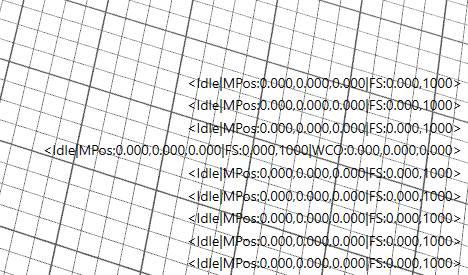
And I’m rechecking the configuration. I may have assigned the wrong limit switch pins. Let me look at this.
EDIT: Yup I messed limit X (it’s in X+ and not X-) and did not enabled pullups.
Do this:
Navigate to the source folder to uCNC/hal/boards/avr and open boardmap_ramps14.h and replace this peace of code:
Changed it, saved it, need to recompile and reupload rigt?
Also tested my limit switches, i dont know if its a standard but when the buttom is pressed, the current is cut. I thought it was the opposite, where the button being clicked closed the circuit. Tested it with a nice janky led setup
EDIT1: now that I think of it, the Probe you also designed opens the circuit/cuts the current, I guess its always like that, just never noticed

 changing it now
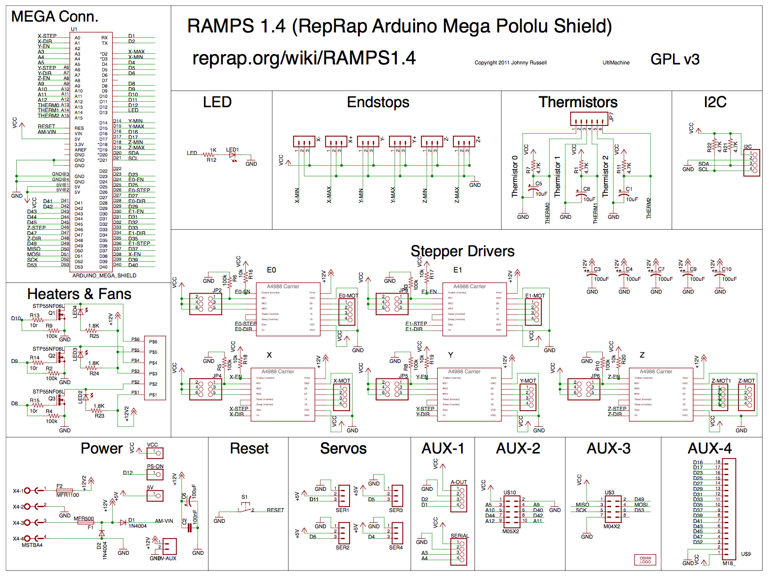