Inspired by these tiny 1mm ID x 3mm OD x 1mm bearings I found cheap on Amazon, and by the lack of space at my current apartment for a full-sized build, I have decided to make a roughly 1/7th scale miniature version of the primo.
Parts for it were actually not that expensive (mostly):
$17/100 681ZZ bearings
$10/10 4mm x 300mm stainless steel rods
$6/5 miniature stepper motors (meant for a camera, 18 degrees per step, 3-5 volts, includes a gear on the end and some sort of mounting plate)
$8.5/2 miniature steppers with a 30mm screw attached (for the Z axis)
An absurd $24 for 200 M1 nuts (brass, I think, as that’s all I could find of that size on Amazon in any useful quantity) and $18/100 M1 tap bolts. But they won’t arrive until sometime in February.
So I also ordered a set of self-tapping small screws. $7/1000 in 10 varieties. I’ll probably mainly use the 100 M1 x 5mm from it if I don’t want to wait for the nuts and bolts.
Arduino with CNC shield - already owned.
Things still left to be done:
Movement system. I’m not having luck finding suitably small timing belts. I might go for a rack and pinion design, or just stick a rubber band or something on it. Or maybe try printing a belt out of flexible filament (or maybe even hot glue with some string as the core). This is basically meant to be a toy, so I’m not too concerned about this at the moment. As far as I know the motors won’t even be strong enough to move it, in which case I’ll probably just attach strings to it and it can sketch patterns from the springs.
Wires. What to use? Possibly I’ll use the wire from some broken headphones (with a mic for the 4th wire).
CAD models of the Primo parts so I can scale it down for the 4mm rods and 3mm bearings and 1mm screws. Unfortunately it’s not a uniform 1/7 scale, but varies from roughly 1/6 to 1/8 depending on the part. If I’m really lazy I might try printing a few of the parts without the extra work and assume I’ll be able to deform them to get the 1mm adjustments that might be needed (possibly with the application of some heat).
Receive the parts and actually build it.
Further in the future: maybe add a laser if it can be moved electronically, as that can be done in a lightweight manner (a couple mirrors and a lens are all that have to be moved).
Wires. What to use? Possibly I’ll use the wire from some broken headphones (with a mic for the 4th wire).
Beware of strand strand count and the sleeve material in wires that move, especially in cable chains. I fine headphone wire very fragile and get wire breaks easily. YMMV.
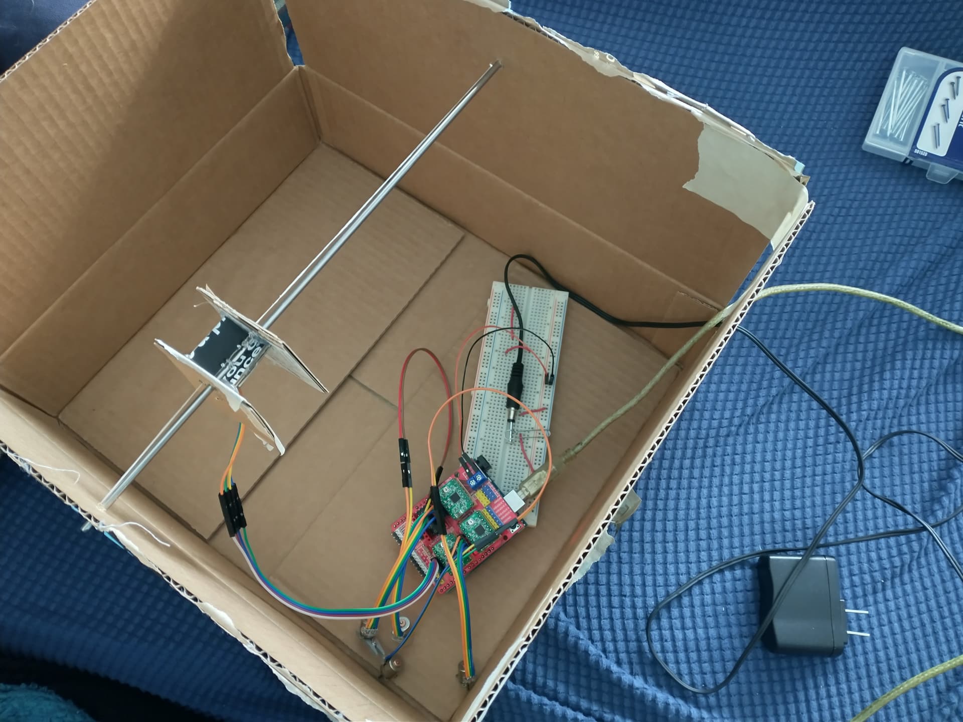
Update: I built a test rig out of cardboard and hot glue to model one of the trucks to confirm the the motors I have would be strong enough to move the machine, and it is working! I’m having some issues where I think the “belt” (dental floss) is catching on either itself or the “pulley” (the motor shaft and a couple pieces of cardboard wedged onto it to hold the belt in one spot). Presently it’s full steps only, as my jumper caps have yet to arrive to enable microstepping.
And here it is in motion, increasing the feed rate through the video.
Unfortunately I broke two of the 5 original stepper motors (the pins pulled out of the motor very easily), so I had to buy some more. To avoid the same outcome, and because the original set was sold out, this time I ordered a set of 50 (for ~$13). They are larger, 1cm diameter, with a longer shaft and no gear. Only 39 arrived intact, but since I only need 5 that’s more than enough.
I also decided on using Cat6 cables, which I was able to get a 5 pack of for fairly cheap, along with a 6 port wallplate. I’m going to see about putting the Arduino in an electrical box with the wires.
What motors are those? I can find the 28BYJ motors are everywhere, which I am told can be converted easily to bipolar operation, but other than that I don’t see any cheap steppers.
Motor step angle: 18 degrees (20 pulses to a circle)
Number of poles: two phase four wire (1 and 3 are A, 2 and 4 are B phases).
Phase resistance: About 21.5 ohms
6V short circuit current: 0.25 A
Package: 50pcs motor
Motor diameter: 10mm
Motor height: 9.8mm
Motor weight: 4 g
Output shaft: 1.5mm
Output shaft length: 7.5mm
Note that they are tiny, though, and not particularly strong. If you search for “micro stepper motor” you should be able to find some more of a similar size.
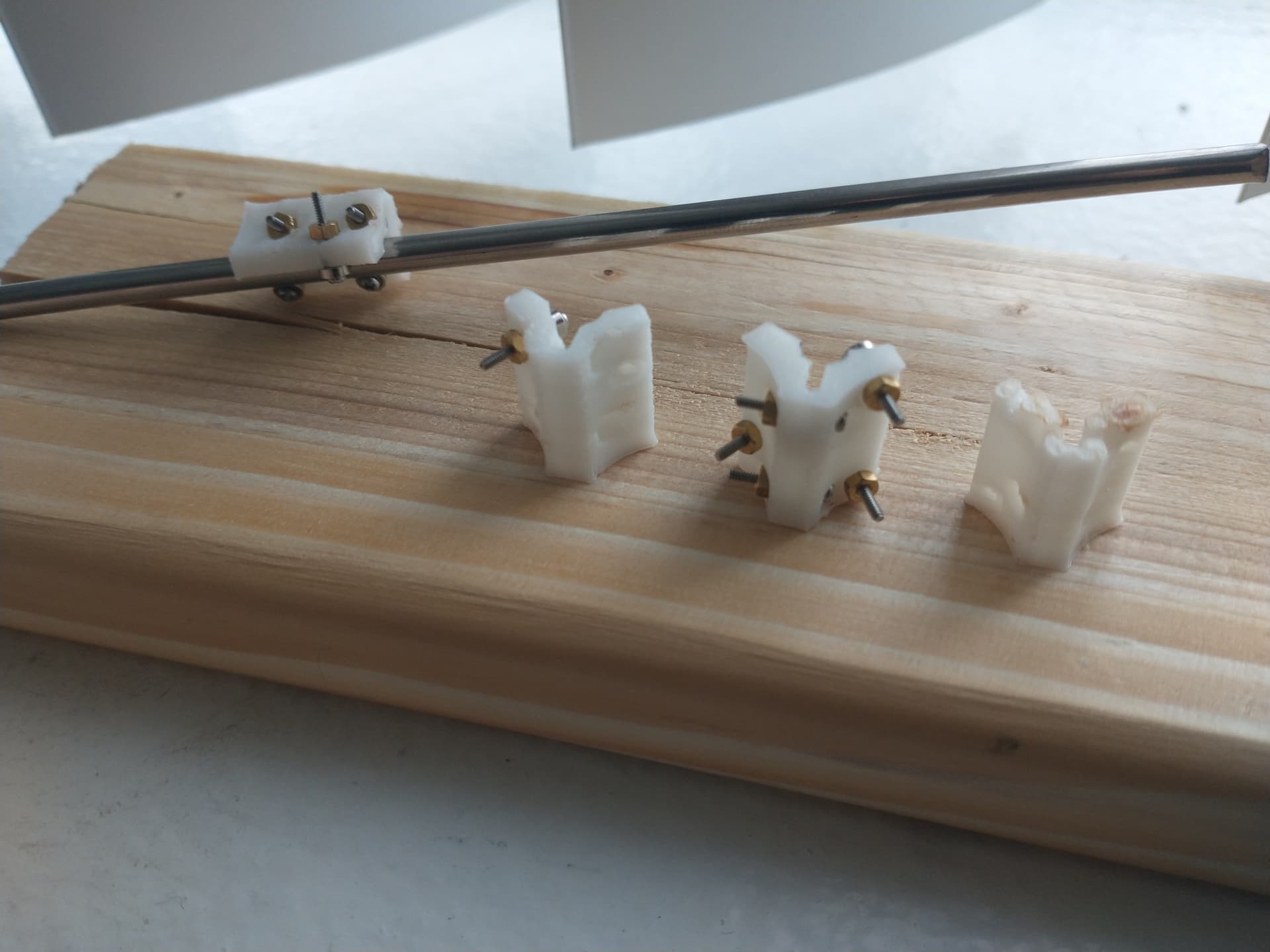
Just got my own 3D printer (a slightly upgraded Monoprice Maker Select Plus, bought for cheap off a guy who was having problems with it and had enough other printers not to want it) and printed the first working truck.
It took a few tries to get there. From right to left, oldest to newest:
A failed print.
The Conduit size scanned down by 1/7 leaves the plastic rubbing the rod and not the vertical bearings
Adjusted padding and such for the bearing so it would fit, but a mistake in the CAD left the vertical bearing holes sealed. The standoff part for the bearing did not have the hole through it.
Fixed that issue and working. Print almost failed in the middle (I think it was grinding the filament or having trouble pulling it from the spool outside the enclosure).
This is awesome… moves pretty fast when it wants to, and I love that scaled down skipped step noise hehe. Can’t wait to see this thing done and running!
Interesting choice using dental floss for the belt. A few ideas… rosin powder the floss so it sticks to the drive pulley better… rubber dipped kevlar thread instead of floss… add external spring tension on the belt (or use a flexible belt… meh)… redesign the belt without idler pulleys, instead wrap the floss around the drive pulley. Some of these ideas are a departure from the mpcnc design… but if such heresy is absolutely required to get it working, then it is not just heresy. I mean, it’s gonna be tough to get the z-axis/core built without some form of “stand off scale” going in to it.
[edit: This could be an epic pen plotter to keep on the desk. My printer excels at accurate dimensions, which would be nice for something like this. So let me know if you run into issues printing… I can print some parts for you… like I said I really want to see this thing roll!]