Modular XZ block (from 1/2" EMT to 1.25" tube)

Here’s a concept I’ve been working on to complement the adjustable bearing block:

The concept is that 4 long bolts holds the block sandwich together. The blocks are individually printed and can be mixed/matched so a user could have smaller Z-tubes than X-tubes (potentially reducing weight/cost without compromising machining results).

Upsides:

  • Everything is symmetric, there’s actually only two unique parts for any given tube size, a left half and a right half.
  • Parts print flat on the machine, so there is a high degree of repeatability.
  • Parts print aligned with the expected loads.
  • Easier center span print
  • Using a long machine screw adds a ton of stiffness.
  • X- and Z- axes can be swapped for optimizing rigidity

Downsides:

  • The required M4 (8-32 in SAE) screws are quite long, and aren’t easy to find in common places (e.g. home improvement stores). Although they can be bought cheaply (<$0.25/ea) in bulk.
  • Not as optimized a design, with the upshot of increased plastic usage
  • Not as compact
  • Inversion of x- and z-tube might not be a good idea
  • Might be hard to get optimal clamping force without damaging prints

Thoughts?


CAD files

https://cad.onshape.com/documents/9bfd836abff9fc3b04fc7b23/w/8b821b524858853269344a9f/e/0c41cd5f8bca95d72528beb6

4 Likes

needs a small gap between opposing faces to allow for the tension to build. It also necks down pretty thin at the widest part of the tube. That section takes all the tension from tightening the bolts. Easy to add to green and yellow pieces. The other two would work better as 1 piece if possible to print somehow (or interlocking features?)

That’s a great idea. This will allow smoother pretensioning of the bolts. I think it’d be hard to do 100%, but I think I could print a little gap between the blue/orange, orange/red, and purple/green. I wonder how easily this can be done to work with a wide range of hardware and prints. Different SAE and ISO steel characteristics will affect bolt stretch significantly, and different materials will alter how much pre-loading it can take before crushing.

I used the original part dimensions, which work fine for 1", but 1.25" really eats into margins. I’m considering growing it to give some more meat to the plastic.

I’m also thinking about whether it’s be reasonable to add a thin rigid material as an endcap, in order to distribute loads. However, I don’t see how to do that without adding another cut part.

I think it’d be possible to print together, at some loss of quality and a loss of modularity. What do you see as the big benefits of an atomic block in this design?

TLDR; Almost ready to print, still struggling with how to resolve hardware length. Made some steps to move from modular to adjustable.

Progress

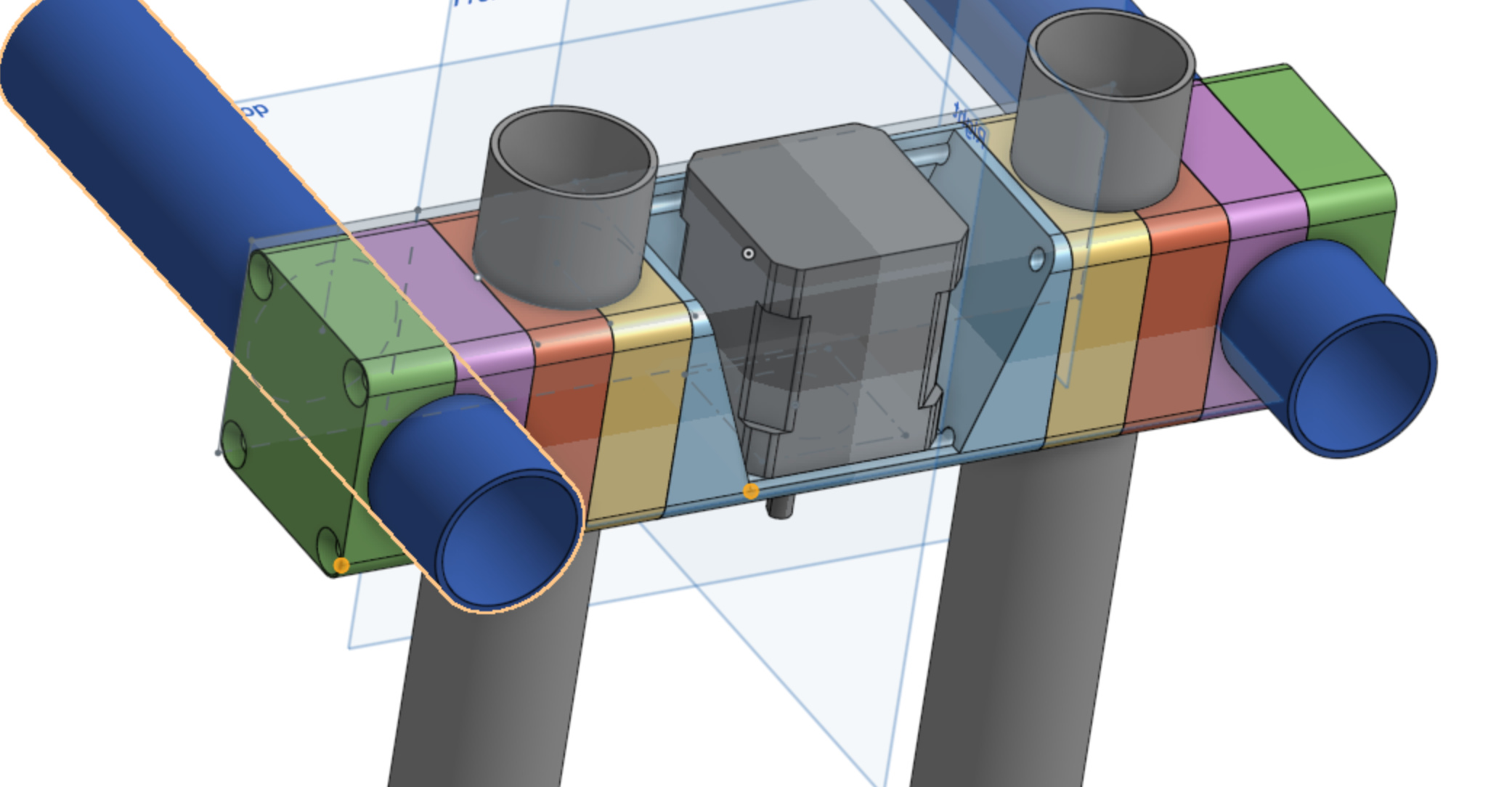
I updated the design with some features which help with adjustability:
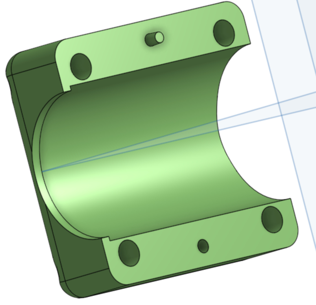
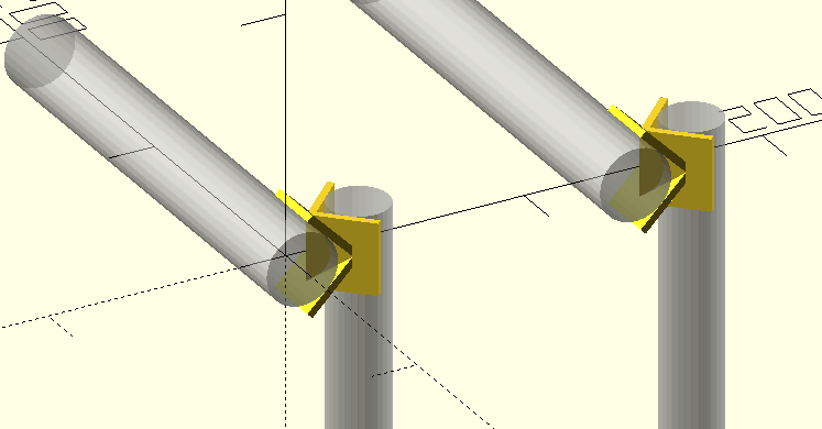
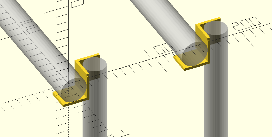
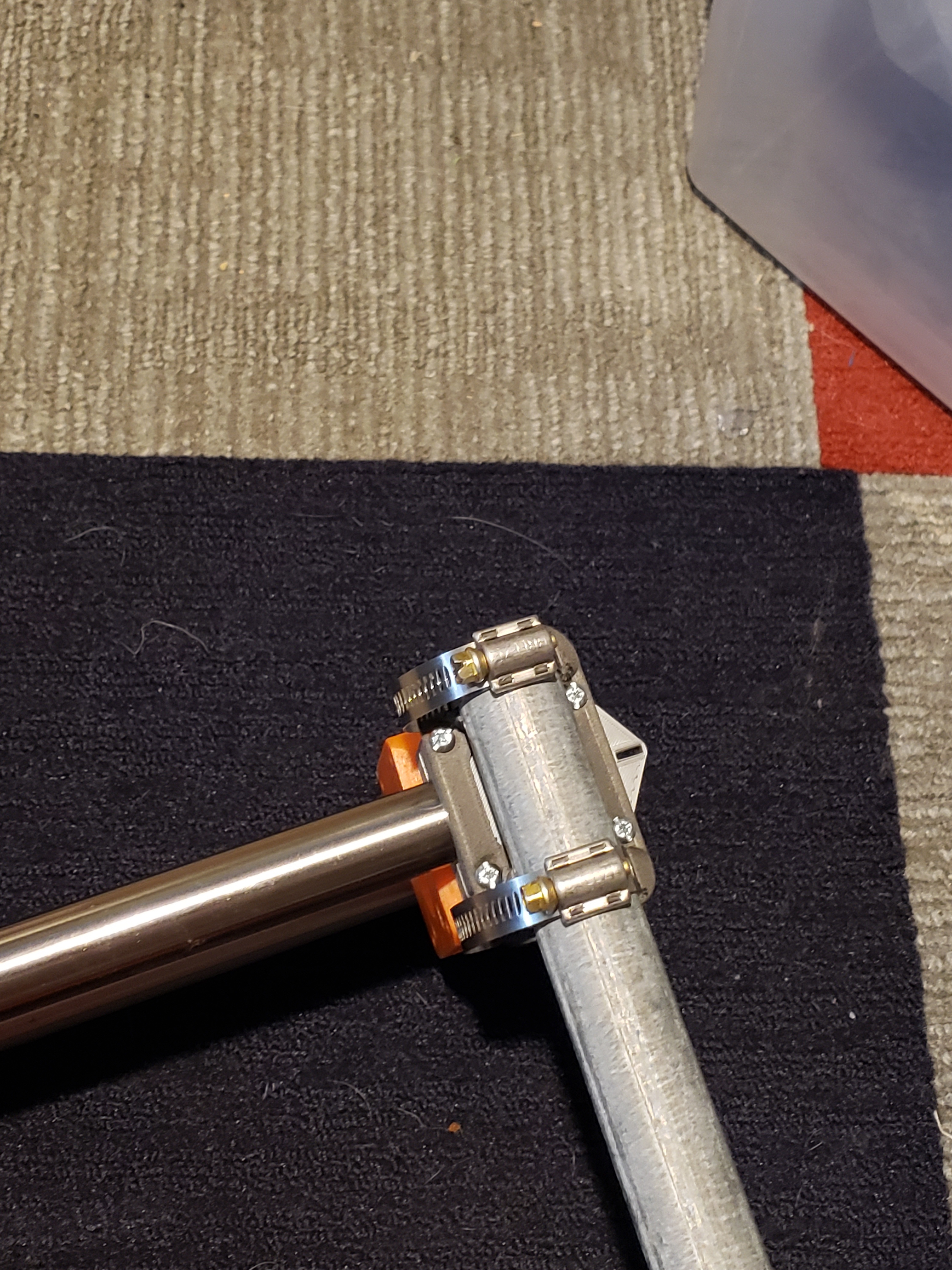
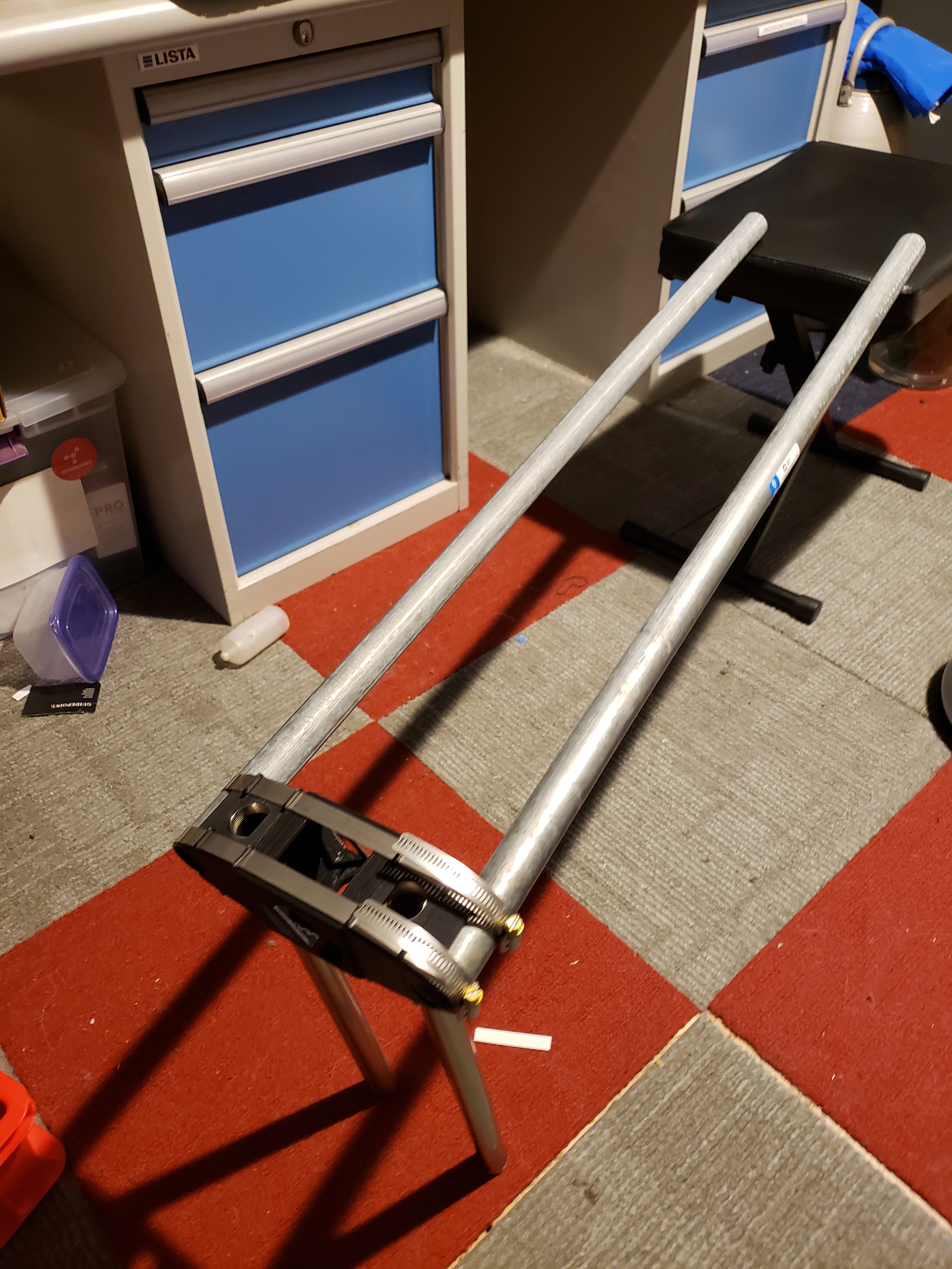
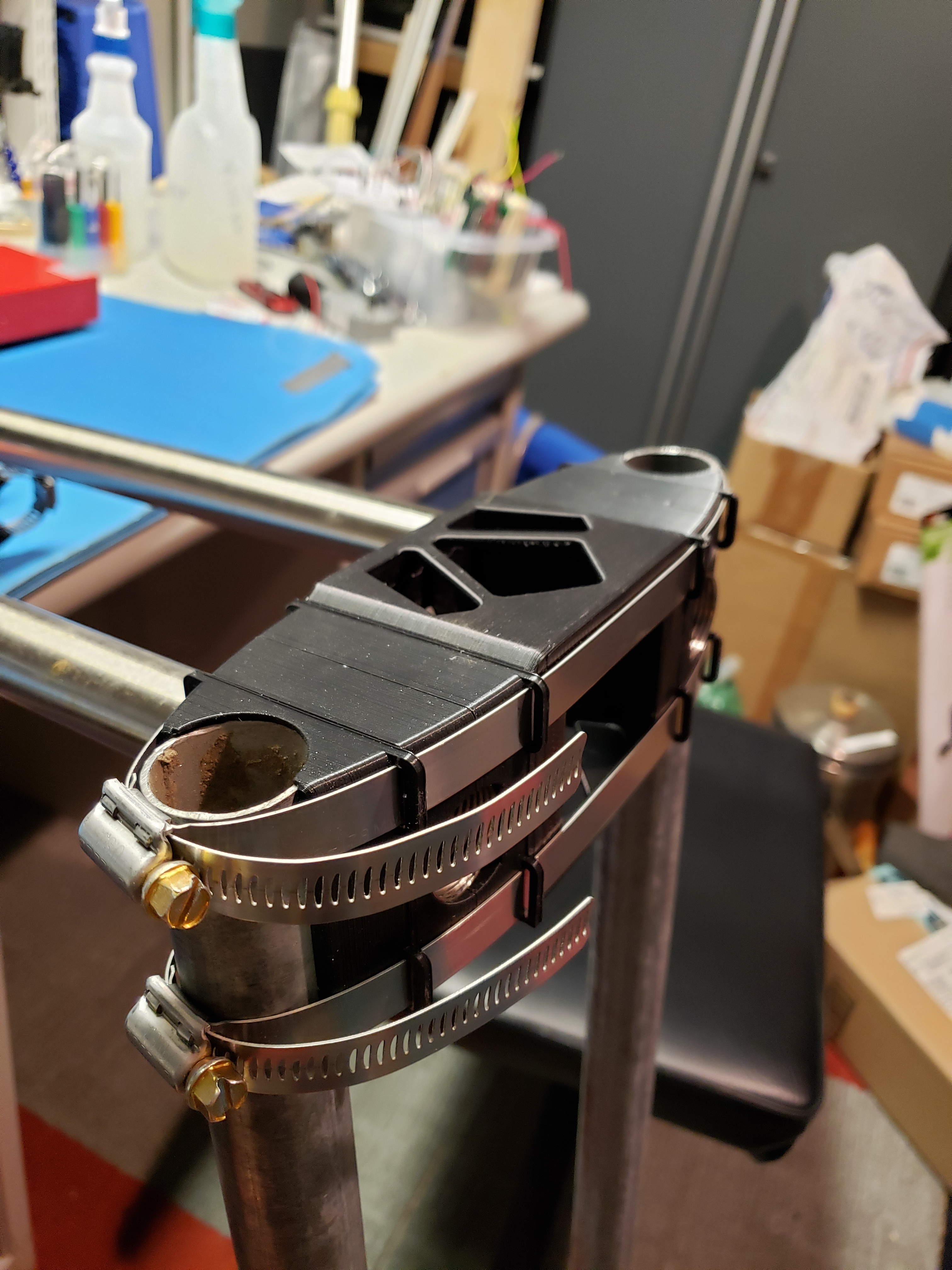
Tube clamps

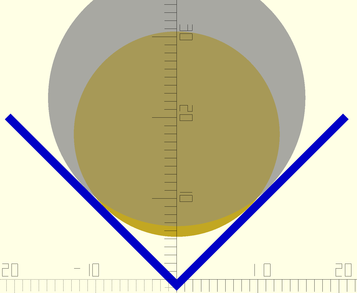
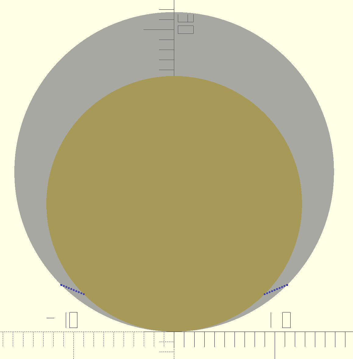
I made a 0.1mm interference fit to help grab the tubes. I have no idea if this is enough or too much. In another post, @vicious1 mentioned that there is a 0.2mm tolerance on tube dia. This sounds like a very bad worst case scenario.

All 8 tube clamps halves are no longer identical, as a function of two features:
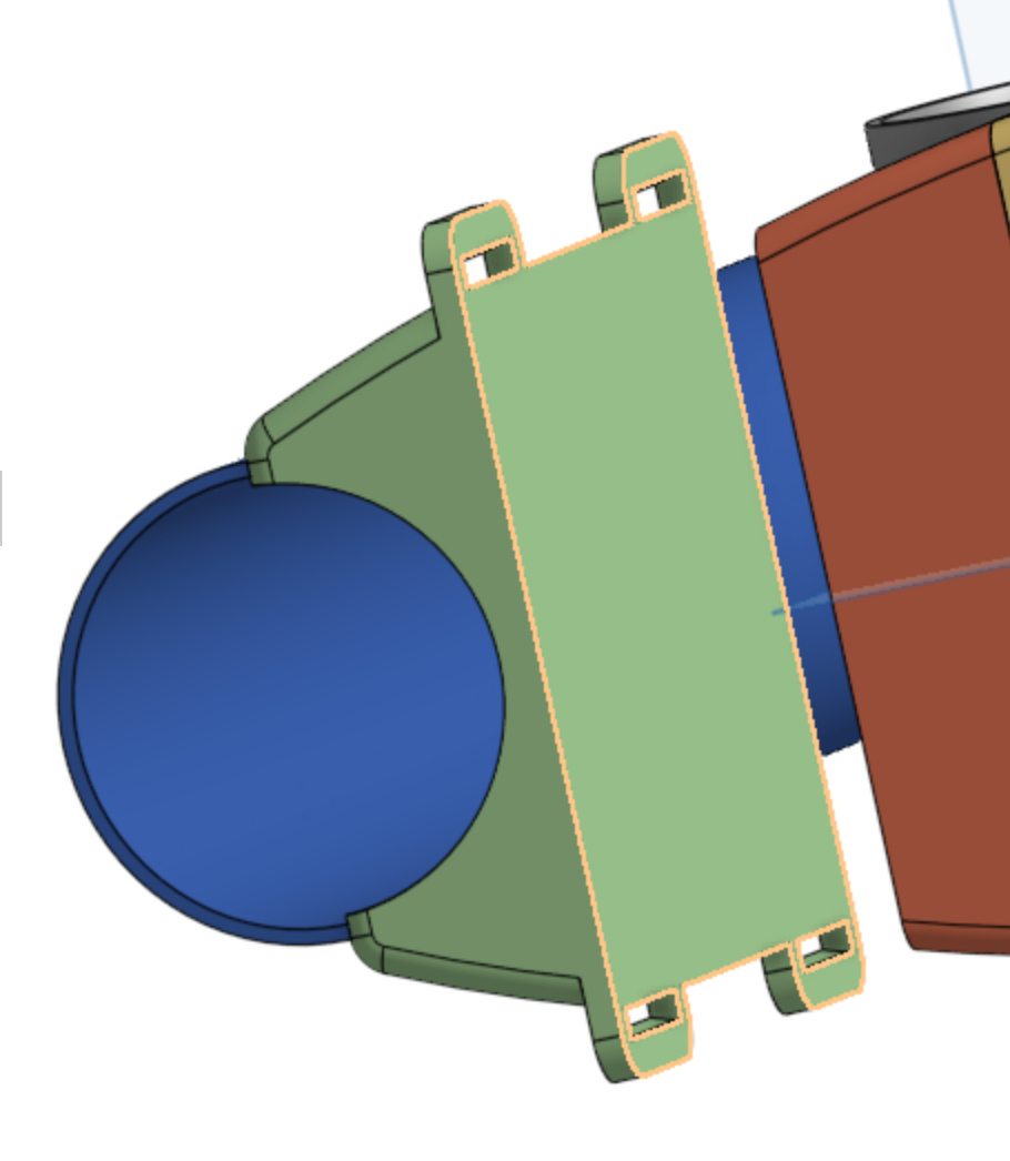
  1. The zip tie mount.
    • This can be resolved by printing a duplicate mount. It won’t add any noticeable weight
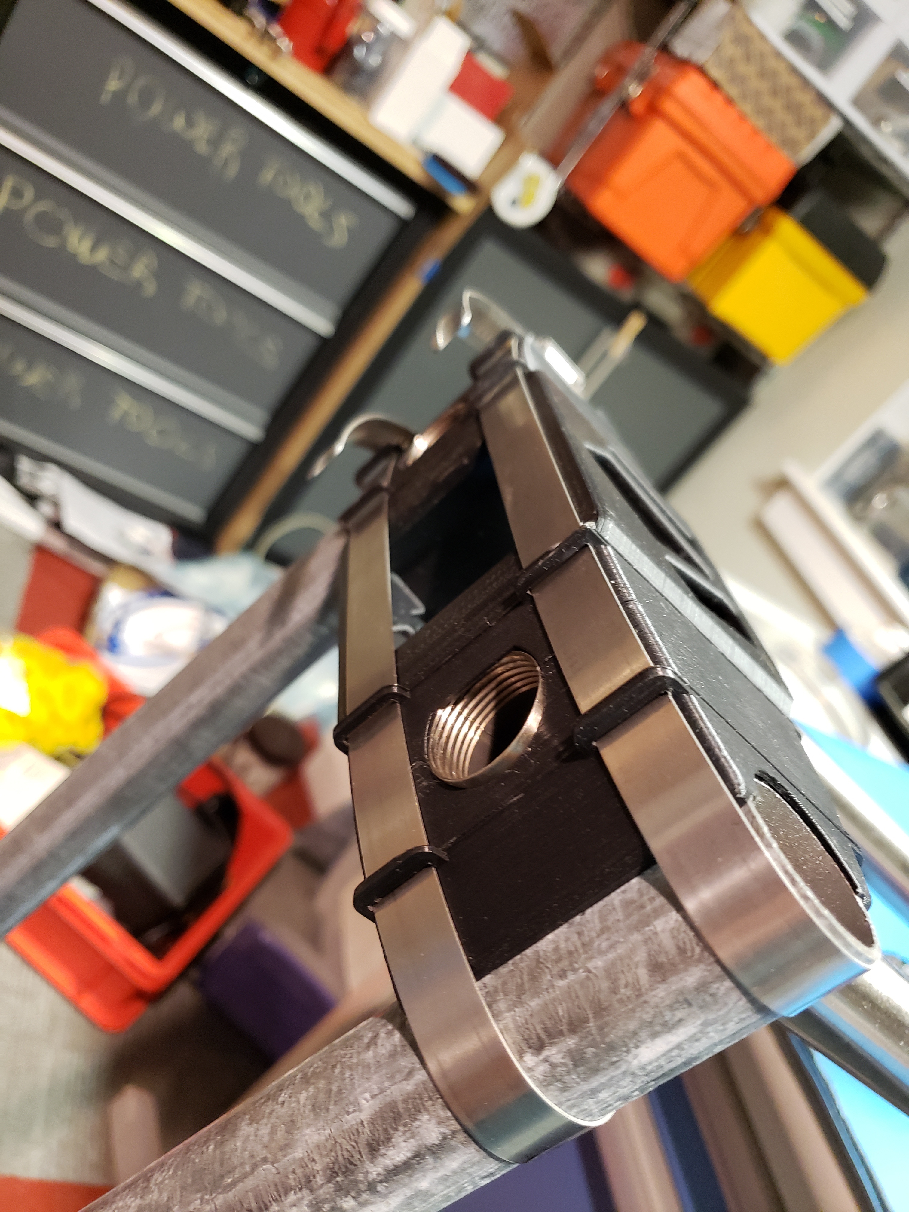
  2. The countersinking and filleting on the end piece.
    • This is harder to resolve, as I am strongly pulled toward countersinking as a way to help align screws as well as provide a localized higher compression strength to resist crushing from the screws.

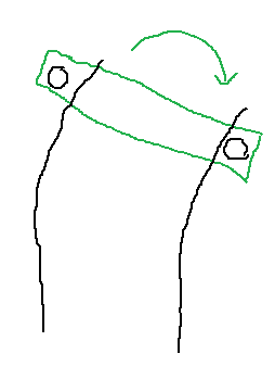
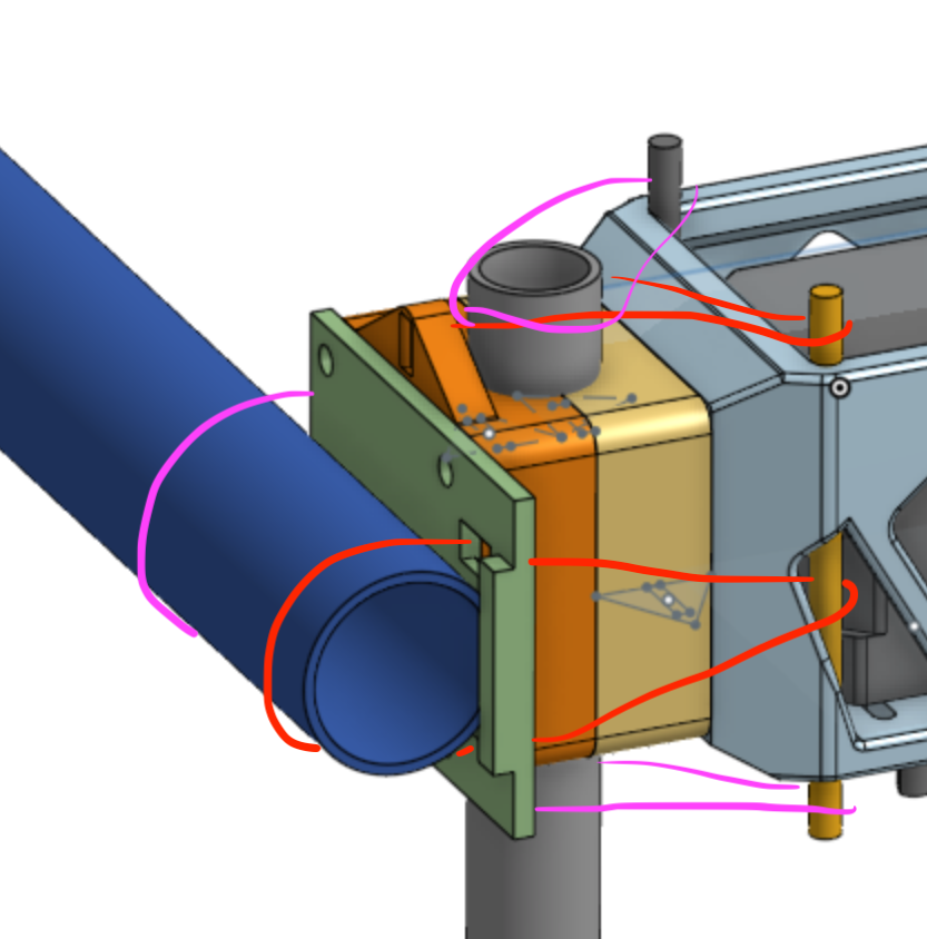
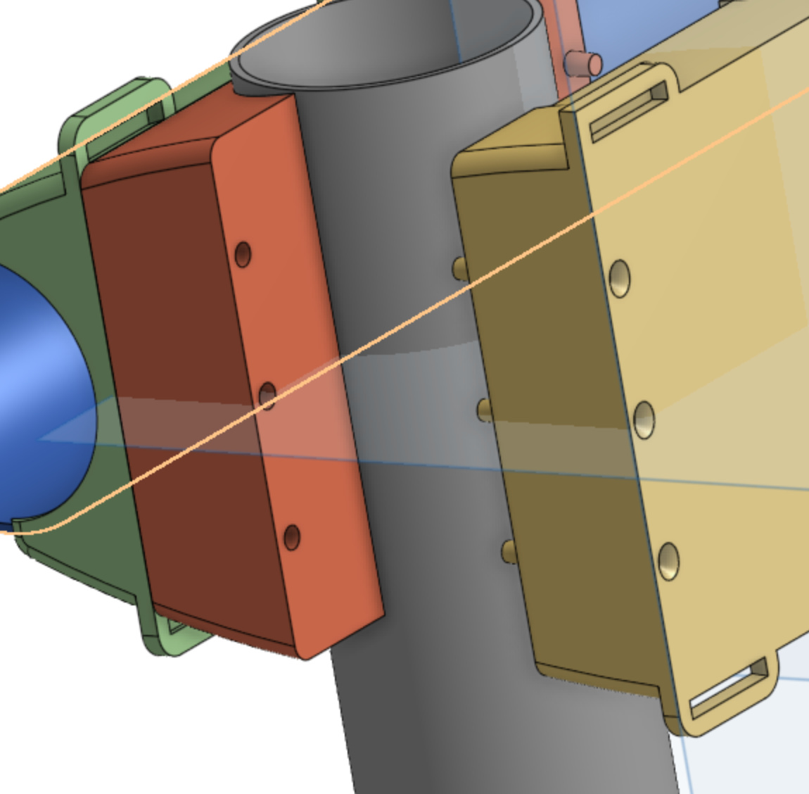
I also added some alignment pins, to handle the case where some slop is inevitable when builders can’t find standard hardware and instead have to use SAE screws:
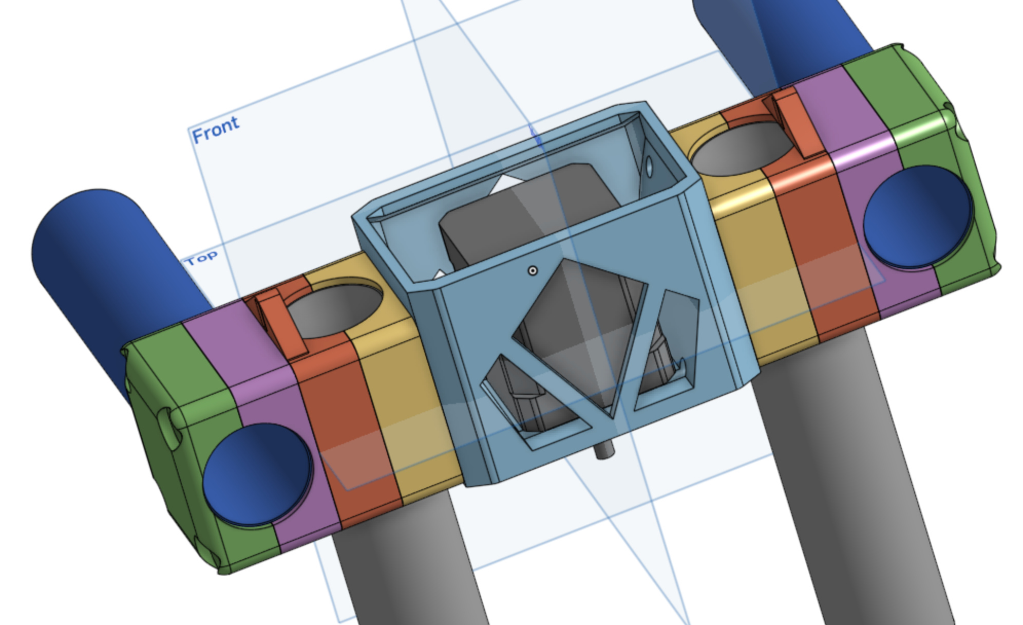
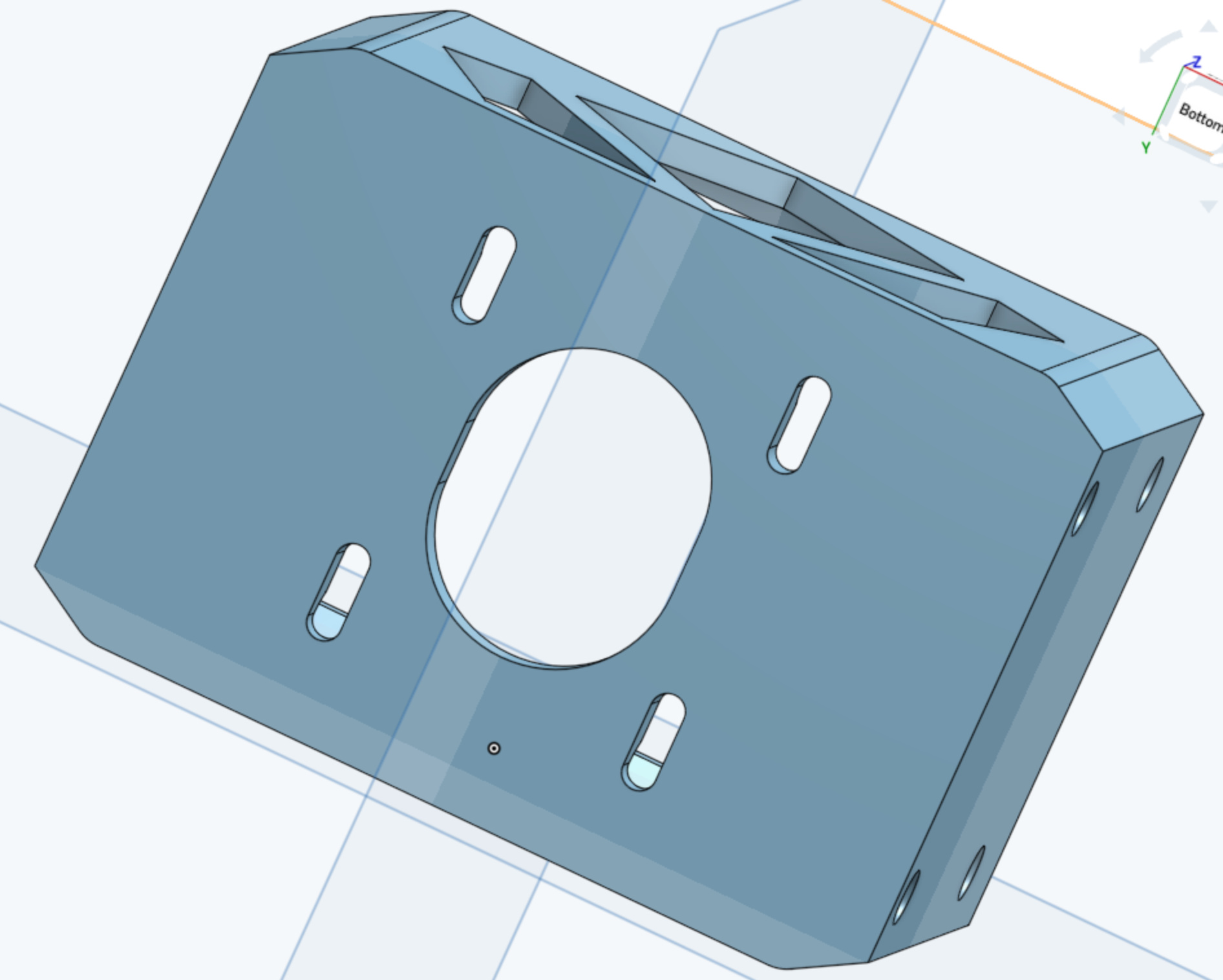
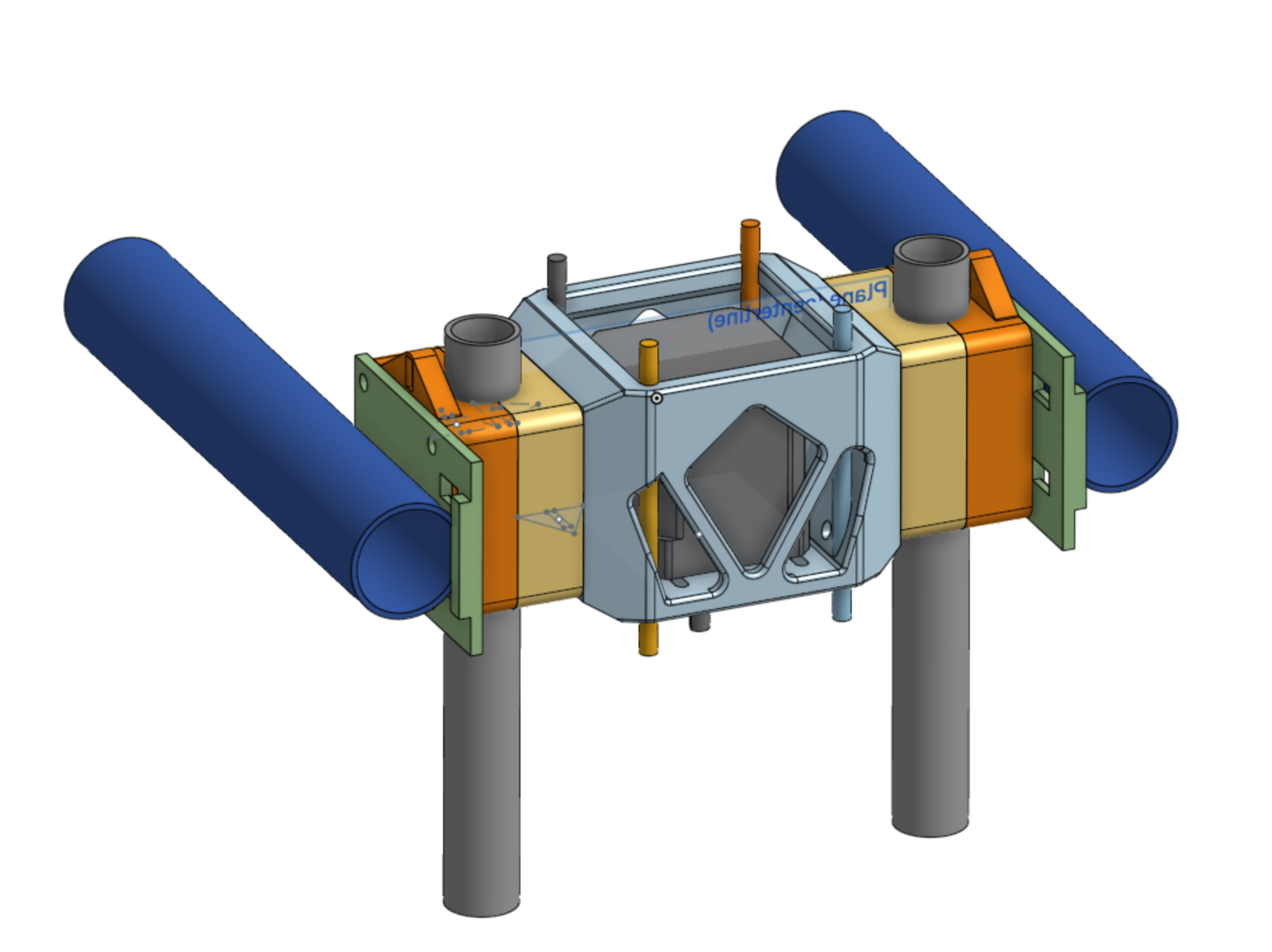
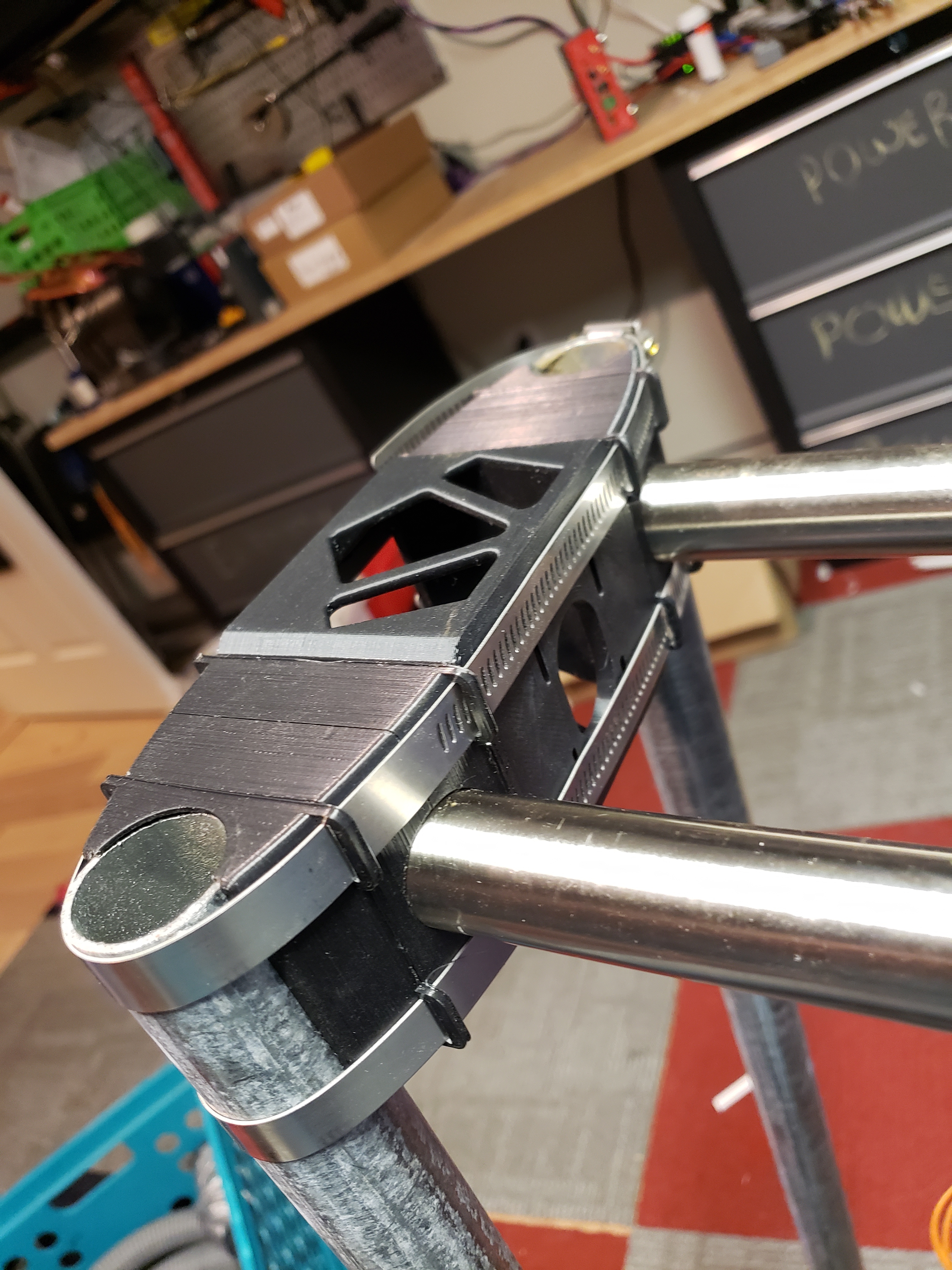
Central span

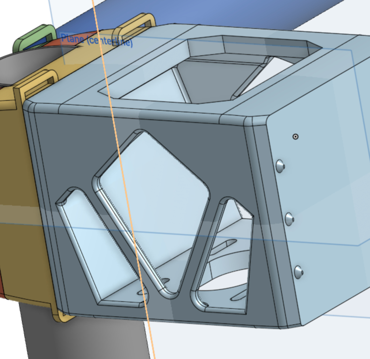
The central span is now symmetric, and includes a significant overhang at the top in order to increase bending stiffness.

I cut some air holes into the sides, these look like trusses but they’re really just designed to let the stepper motor breath better. I’ll print the central-span out of color-changing PLA and if it doesn’t heat up then I’ll probably remove these features as they complicate the build, reduce strength, and likely don’t reduce weight (because infill is low density, whereas part walls are high density).

I added slots so the motor could be adjusted. The slots are quite large right now, but should shrink in size when the clamps are changed for offset tube centers as a function of tube diameter.

Summing up

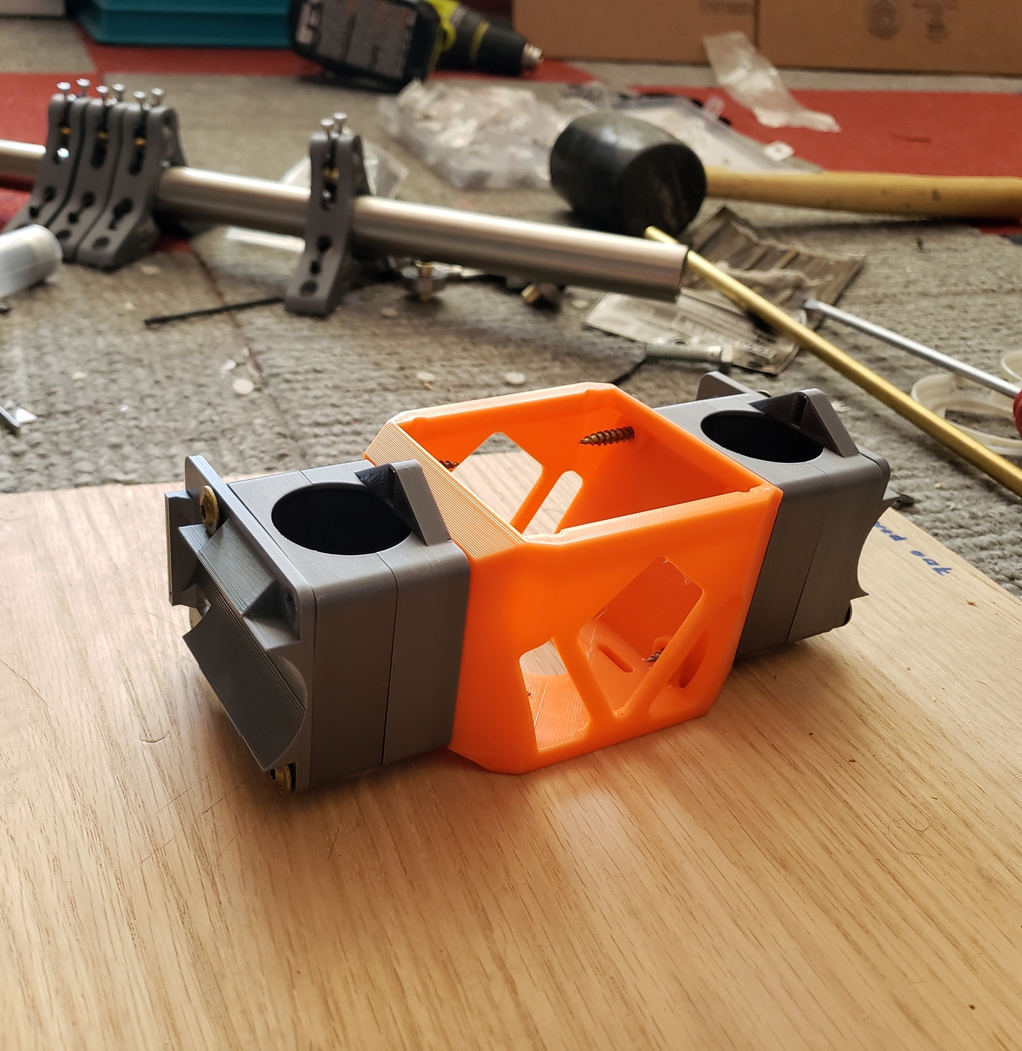
It’s about ready to print. All I need to do is provide some flats for nuts in the central span.

I remain dissatisfied with the requirement for a very long screw. While compatible threaded rod (aka all-thread) can be found at almost any hardware store, and perfectly sized screws can be supplied either in kit form or sourced from McMaster/Amazon, it still seems like a step backwards. I would love to resolve this, but I haven’t come up with any bright ideas yet.

One solution is to back off trying to have a modular approach which allows for both 1.25" x- and z-tubes. There’s really no need for that large a z-tube, and IMO the only reason someone would ever want to use that is because they’re having trouble sourcing anything other than 1.25".

If we could relax the requirement to support uniform tube sizes at the 1.25" mark, then we fall below 70mm, an important threshold for typical bolt length.

2 Likes

I think you are coming up with great solutions. Don’t let my observations sway you.

That screw could be really tough to find. You might just want to leave enough room to do all thread from one end to the other. You are using a very large stack of parts on each side, all of them using the build plate surface. I would venture to say 50%+ use bed leveling (most without the error fade turned off) This is going to mean some really funky angle stacks. I would at least combine the orange and purple, and yellow and blue parts so you have less error stack.

4 Likes

My printing experience is limited and I’m not sure when my bed adjustment is my fault or accident Ryan’s parts work for me so he must have a idea about how us printer jobs work

1 Like

I’d considered a threaded rod the entire length-- nice and rigid!-- but I don’t love how much the plastic parts have to grow in order to avoid the motor-- around 1cm.

:open_mouth:

I hadn’t considered that at all. Maybe I’ve been spoiled by well-tuned printers, or perhaps I’ve never had cause to notice the effects of bed leveling when assembling parts.

One possible remedy is to print parts at the same time, so that the out-of-level reference angle cancel outs when the parts are rotated 180 degrees:

  • This has the downside of making it hard to print an individual replacement part, you’d want to print whole sets at that point.
  • It’s also not great because then parts are no longer interchangeable.
  • Lastly, it does nothing for the center span (blue), since that’s printed from a different angle.

I’m reluctant to combine the center with the yellow part, since then modularity is lost, and the print direction becomes a compromise. Likewise for the purple and red. (Stupid compromises, what’s wrong with wanting strong, precise, AND cheap?)

I wonder if using threaded rod isn’t a decent answer, since so long as its tightened down evenly and sufficiently to eliminate gaps it can control for variation in the stack.

It seems to me the primary load that these parts have to support is to hold the X rails perpendicular to the Z rails. In other words, the purple and red pieces must avoid twisting relative to each other.

The X tubes are not under any axial load, so it doesn’t require a lot to keep them from slipping axially. Covering the ends with a lip means that the tubes need to be exactly the right length (or a bit short) to get the wheels to track parallel. Since they are not under any load I’m not sure of the advantage.

Z tubes have a little bit of axial load and the opposite end is free, so I think a lip makes more sense there.

The X tubes need to support being pushed horizontally, which is naturally going to be stiff. Pushing the X tubes vertically is necessary for a stiff Z axis and also to prevent tipping in the Y-Z plane. For a stiff Z axis the transmission of the load from the X tubes to the Z lead screw needs to be decent, and for tipping it needs to transmit the load from vertical load on the X tubes to vertical load on the Z tubes, which is ultimately supported by the plate. These are relatively easy to make stiff.

The point is that the different modes of deflection are very uneven in their importance. I might not have identified the deflections correctly but I do think they are unequal. Maybe the green and yellow parts could be replaced by zip-ties and the red/purple parts deserve all the focus.

As for being adjustable or modular, I am still unclear on one thing, which is whether the tube spacing is going to remain the same so the other parts remain compatible (given their own adjustment) or do you have families of parts that go together and possibly a size-dependent plate?

1 Like

That’s really good insight! If you look at the axial X forces, they come from the belt and are all carried by the triangle on top of Orange. So Green and Purple have zero axial load.

Removing Green entirely and replacing it by zip ties might be workable. You’d still need a cradle (Purple), because in addition to the downward cutting forces (I’m assuming that nothing resists upward movement except for gravity), there’s also a twisting moment across the pair of X tubes.

Here’s the idea implemented. It uses hose clamps or hefty zip ties (hand drawn in red) to tightly bind the X tube to the Purple cradle.

The Purple cradle is aligned with the stack with some counterbore (or panhead) screws. By removing Green, the new bolt distance is <50mm, so M4 (or SAE #8) are easy to find.

What do you guys think, are we getting close?

Sigh… this is hard. Making things be adjustable in 3D adds so many layers of complexity. I am on the lookout for an idea which would allow for this to be completely adjustable, instead of only partially.

I currently feel that families of parts is best. We won’t know for sure until there’s some testing, but my hunch is that keeping the tubes as close together as possible makes for zero compromises.

I’m hopeful with some good choices the only part families would be the XZ modules-- the Y-plates and spindle plate would have multiple drill holes and therefore not require separate DXFs.

But if someone can figure out how to make the cradles adjustable and yet rigid with a fixed reference, I’m game!


P.S. Regarding the lips, I got them from Ryan’s original design. Giving it some thought, they still seem useful. If the tubes are cut to precise lengths (which is pretty easy to do since you can line them up against each other), then the lips go a long way to guaranteeing parallelism during a teardown/rebuild.

P.S.S. I think you might reexamine potential vertical forces transmitted to the Z tubes. The vertical forces all come from the lead screw, but the tubes themselves translate freely on the bearings.

Ah you’re right about the axial load on the Z tubes. It’s not really axially loaded – the tipping moment in the Y-Z plane is purely a bending of the Z tubes since they move freely in the rollers.

image

Another idea, as a brainstorm type idea, i.e. not necessarily ‘good’ idea but might stimulate some other thoughts, is using V-shaped blocks to accommodate a range of tube sizes, plus a non-symmetrical arrangement, like this:

This way the center-to-center distance of X tubes and Z tubes are invariant to tube size. The other parts would need to accommodate the varying diameter but could count on a fixed distance.

I haven’t thought through all the implications, this is just the starting point for an idea.

3 Likes

Hoo, boy, I got carried down a hole with this. A V isn’t the optimal shape for maintaining the distance from the bottom of the circle to a fixed reference, so I decided to figure out what is:

And then did the numeric integration in Julia:

R_0 = 17.9  # 1/2EMT trade size, in [mm]
R_final = 1.25*25.4  # 1" tube, in [mm]
dR = .1  # Step size, in [mm]

theta_D_0 = 30  # Initial tangent angle for "v"

# Convert to radians
theta_R_0 = theta_D_0 *pi/180

# Initialize x and y location
x_0 = R_0*sin(theta_R_0)
y_0 = R_0*(1-cos(theta_R_0))

# Initialize arrays
R = collect(R_0:dR:R_final)
numSteps = length(R)
x=zeros(numSteps)
y=zeros(numSteps)
theta_R = zeros(numSteps)

# Seed integration arrays
theta_R[1] = theta_R_0
R[1] = R_0
x[1] = x_0
y[1] = y_0

# Loop over the step sizes
for i=1:length(R)-1
    # Calculate numerical derivative
    dxdR = (1-cos(theta_R[i]))/(tan(theta_R[i]) - R[i] *sin(theta_R[i])^2*(sin(theta_R[i]) - cos(theta_R[i])))
    dydR = tan(theta_R[i]) * dxdR
    dthetadR = sin(theta_R[i]) *(sin(theta_R[i]) - cos(theta_R[i])) * dxdR

    # Crappy Euler integration, but it works!
    delta_x = dxdR * dR
    delta_y = dydR * dR
    delta_theta_R = dthetadR * dR
    
    x[i+1] = x[i] + delta_x
    y[i+1] = y[i] + delta_y
    theta_R[i+1] = theta_R[i] + delta_theta_R
end

plot(x=x,y=y)

Here’s the optimal shape, with x-y location in [mm]:

And the error, in [mm]:

I didn’t plot it against a V, but the math shows about 4mm of error by the time you get to 1.25". That adds up!

Is any of this worthwhile? Who knows! I didn’t exactly use it to make a new part yet, so :stuck_out_tongue:

1 Like

Alright! I’m not the only one who does algebra for fun on the weekend!

And you’re right that the bottom edge of the circle is not at a fixed location as the diameter changes.

Empirically (empirically in simulation) for a 90 degree V I’m seeing between 1 and 2 mm of difference between 1 inch and 1.25 inches. The center of the circle should be r * sqrt(2) away from the vertex, and then the bottom edge would be r away from that, so the distance between the vertex and the bottom edge should be r * (sqrt(2) - 1), or about r * 0.4142. For a difference of 0.25 inches in diameter, the radius would differ by 0.125 inches, which is 3.175 mm. The bottom edge position would differ by 3.175 * 0.4142 or 1.3 mm.

As for an alternative shape to reduce the position of the bottom edge, I’m not sure a shape exists because for two circles to coincide at the bottom edge there are no other points where the small circle can be supported that are not inside the larger circle.

Considering circles of varying radii which coincide at the bottom edge, one could construct the locus of points tangent at a fixed angle, but these points don’t produce a surface where all the circles can rest. The larger circles can’t reach the wider points because they would collide with the narrower ones.

I doubt this is equivalent to your solution because it is more direct, but qualitatively it looks similar.

If you do need a fixed distance, say for a fixed clearance between the tubes and the plates for example, I think the only way is to support it at that bottom edge, which is also possible but no longer symmetrical about the Y axis:

As for if it is worthwhile, hey don’t let it stop you from having fun. And maybe it is or maybe it feeds into something that is.

It works, so long as as the tubes are able to pass through walls.

Pesky reality.

I think what would need to happen is a flat contact point at the 0 degree station, and some kind of screw adjustment at two other stations, e.g. ±30 degrees. This would capture the tube by providing three points of contact, one of which is a known reference.

However, that could prove to be very fiddly. Tuning those contact points will be challenging because they will point load a thin-walled tube. I’m not sure it’s worth the cost vs a modular approach, where we can tune the tube placement while maintaining good fit.

I have incorporated feedback. This thing looks like it needs some lasers now…

I built this new XZ system using zip ties (or some other appropriate flexible tensioning element) to clamp the tubes. There are now four vertical rods which serve as posts to anchor zip ties. These rods are metal (they can just be screws, threaded rods, or hollow brass tubes), and because they are firmly embedded in the center span I believe I can really turn up the clamping forces. These posts can be used for anchoring all four tubes.

In addition, I kept the original bolt through-holes, but these might actually no longer be necessary if the zip-tie approach can make things stiff enough. I’m not optimistic, but it’s easy enough to try that once it’s set up I’ll run an experiment with and without bolts.

Lastly, the z-tube CAD now automatically places it in the correct location so that no adjustment is necessary on the y-plate. The screenshot shows a version with 1/2"EMT for Z and 1"EMT for X, so there’s quite a stark difference between the two.

Thoughts?

Filled with concrete?

1 Like

Received the printed parts:

Unfortunately, the incorrect configuration got printed, so I will have to wait on some new clamps. But the upside is that the middle span doesn’t need to be swapped out, so the printing effort is low. Score one for modularity!

One thing to report is that the center span is super stiff. I think it might take some engineering to get the overall assembly to be equally stiff, but it might not actually matter. Once the first model is together, I’ll see if there’s any appreciable flex.

I also need to buy some hardware, I forgot to make a purchase on some long M4 (or SAE #8) bolts. So it’ll be another week before this part is ready for a test fit.

3 Likes

Finally, my access to 3D printers is coming back slowly but surely. I just got my first part off the MarkForged and I think that hose clamps (aka jubilee clips) are the way to go for this. They’re strong, light, and make for a very stiff structure.

Here’s the updated model, which dispenses completely of all bolts and only uses two hose clamps like you’d find at any hardware store (likely in the ductwork section).

  • Because the metal fully crosses the assembly, it stiffens the entire part. Before, the screws stopped when they entered the middle section, leaving a “gap” in the metal superstructure.
  • The gentle arc ensures that the hose clamp lateral pressures are well distributed
  • The gentle arc also helps give lateral stability to the overall assembly.
  • The tabs are to retain the hose clamp for ease of assembly.

The only concern I have is that there are no features to prevent the X and Z tube from rotating relative to each other. For the other block interfaces, there are always alignment features designed to prevent rotation:

However, the mating between the Z and X blocks is perfectly smooth, and because those mating surfaces are the respective bottoms when printing, there’s no ability to print in features.

Advice on how to approach this? I’ve considered:

  • adding a hole into which a rod can be slid internally
  • adding a groove along the outside which can accept an external piece of flat metal or wood
  • gluing them together at the faces
  • adding an internal square pattern and printing the corresponding part which would function like a dovetail.

Thoughts?

Maybe the red and green parts could be a single part?

The red portion would have overhangs if it were printed with the X axis vertical, but you wouldn’t have to enclose the Z tube with a full 180 degrees like you do now. The MPCNC Burly rollers for example grab the tube by less than half the tube circumference and have a printable 45 degree overhang.

1 Like

That’s an intriguing idea. I am somewhat concerned about printing in such a way that the weak inter-layer orientation is aligned with the Z tube. I don’t have a strong notion about how high the forces are, and whether they could conspire with vibration to ultimately cause delamination of the print.

Is there real-world experience with aligning the layers in this manner?

Success! It was a bit persnickety to assemble the first time, because the middle section didn’t have any retainers. I’ve fixed that for the next print.


I’m very pleased with the rigidity, and everything works as it should. You can really clamp down hard and the center span has no problem supporting the load.

I’m still a little unsure of the best way to align the x-cradles with the z-clamps. There has to be some alignment which is more rigid than friction between two PLA blocks. The loads aren’t high, but if the system ever got out of balance you could get some trapezoid error across the width of the CNC.

I gave some thought to @jamiek’s idea, and I’m not convinced I can pull it off, plus we lose modularity. So I’m thinking maybe the best thing is some small wood screws. These features would be very easy to print and assemble. They’d be internal to the structure and so thus invisible. The main issue is that consistently sourcing wood screws is possibly a lot harder than machine screws.

Another possibility is double-sided masking tape, which is similar to gluing, I guess. And possibly just as hard to undo when there is the inevitable assembly misalignment. So I’m not a huge fan.

Thoughts?

1 Like